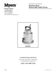
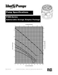
PACO<strong>D1d.1</strong>7/05Supercedes 1/90PUMPSNOTE: REFER TO D1d.3 FOR OPERATION ANDINSTALLATION INSTRUCTIONSOF LIQUID LEVELCONTROLS.• Machined face of motor and bracket should beclean. Install coupling insert in position on pumphalf-coupling (half-couplings should not touch eachother.) Assemble motor, on pump bracket withconduit box located as required. Check couplingalignment with straight-edge.• Refer to appropriate liquid level control instructionsheet for installation and adjustment.• Bolt manhole plate to cover, using gasket forgastight installation.• MICROMETER SHAFT ADJUSTMENT(optional.)To raise shaft and impeller, loosen locknut 9A.Holding the shaft, use a spanner wrench, to turnbearing adapter 26H counter-clockwise untilimpeller makes contact with volute. Then turnbearing adapter clockwise 1/2 to 3/4 of a turn andtighten locknut in position. Check to make certainshaft turns freely. (See Fig. 4a)FIGURE 3a: Non-Clog Pump, <strong>Type</strong> NC• On a gastight installation, install the length ofpacking material on the sump flange. Overlap(side by side) the packing ends four to six inchesfor a complete seal.• Install sump cover over sump basin in a horizontalplane, and position the cover so that pumpsubplate opening(s) will place pump dischargepiping at required position. sump cover should beso positioned that the liquid level control parts arenot placed directly in the parth of the inflow enteringsump. Where this is not possible a baffle isrequired to prevent turbulence of the liquid frominterfering with the proper operation of pump andlevel controls.• If pump bearing have been specially ordered withclean water lubrication, connect the lines, abovesump cover to a clean water supply. If to bemanually operated open valve prior to starting unit.Close valve after unit is shut down. On automaticoperation, insert a solenoid valve, of same voltageas motor, into clean water supply line, and connectto motor or motor starter to open when motor startsand close when motor stops. Fres water supplyshall be minimum of <strong>10</strong> PSIG above pump dischargepressure at 1-2 GPM.4• Remove any shipping supports or coverings on thepump unit before installation.• Install pump and subplate assembly(s) in positionon sump cover, using gasket between subplate andsump cover for a gastight installation. Boltsubplate(s) in place.• Install motor half-coupling on motor (unless themotor is assembled to the unit.)• CAUTION: Do not apply excessive force to installcoupling or motor bearings can be damaged.FIGURE 4a: Typical Micrometer Adjustment
PACO<strong>D1d.1</strong>7/05Supercedes 1/90PUMPSF. PIPING GENERALII.OPERATION• Connect pump discharge and vent piping asrequired by local code.• Install a union or flanges in piping at pump, clear ofsubplate, so complete unit on subplate may beremoved readily.• Discharge piping should be aligned and supportedproperly so that no strain is transmitted properly sothat no strain is transmitted to neither the dischargeconnection nor the pump assembly.• Avoid unnecessary bends and fittings in thedischarge line. Where necessary, use 45° or longsweep90° pipe fittings to decrease friction loss.• To prevent problems associated with dischargebackflow in single or duplex installations, installa check valve in each pump’s discharge line.Install a gate valve between each check valveand the header, to facilitate examination orrepair of check valve, or removal of pumpingunit.G. EXTERNAL WIRING• Motor starter(s), with overload protection, mustbe selected correctly for the motor rating.Follow instructions of motor and starter manufacturersin connecting them and follow wiringdiagram for the liquid level control that is containedin its instruction sheet. Be sure thatmotor overload heaters are properly selected foroperating voltage and amperage.• If atmosphere where motor and/or electricalcontrols are lcoated is damp, appropriateventilation and method of keeping the area is dryis essential• Install electrical wiring in accordance withNational Electrical Code Standards and applicablelocal regulations.• Check final connections by applying power tomotor for an instant, to observe direction of shaftrotation. Shaft must rotate in direction of arrowon pump unit. This is clockwise, looking downon the motor. If rotation is not correct, for threephase motors interchange any two power leadsat top or bottom of motor starter. If motor issingle phase, refer to the motor wiring diagram.A. PRE-START CHECK LISTMake the following inspections before starting yourPACO type <strong>SL</strong> or NC Vertical Pump:Make certain that the motor’s starter nameplate,voltage, phase and frequency matches the powersupply. Check liquid level control wiring diagrams.If motor and pump have been in storage for anextended period, turn shaft by hand to makecertain it rotates freely and the motor bearings areproperly lubricated per maitnenance instructions.Try the motor roation momentarily to be sure it iscorrect according to the arrow on the pump (seeG-4)CAUTION: Never run pump dry. Serious damageto unit can result.Check piping to make sure that all connections aretightly made up. All valves open as required.Make certain level controls are in required position.NOTE: Refer to 1854.615 for operation andinstallation instructions for level controls.B. STARTING THE PUMP• Fill sump with liquid well above pump end, toactuate the high liquid level control.NOTE: Remove all foreign materials from sumpbefore starting pump.)• Start the motor if on manual control, or allow levelcontrol to start if on automatic control. Run pumpthrough the cycles to insure that float switches areworking correclty.• Check all discharge connections above sumpcover for liquid leaks.• Check and record the voltage, the amperers perphase, and the kilowatts if a wattmeter is available.If voltage is above <strong>10</strong>% or below <strong>10</strong>% themotor nameplate voltage, shut unit down andcheck wiring connections. If wiring connectionsare proper, notify the power company.5