D1d.1 Pages 1-10 Dated 4-10-06 Type SL & NCC.pmd - Paco Pumps
D1d.1 Pages 1-10 Dated 4-10-06 Type SL & NCC.pmd - Paco Pumps
D1d.1 Pages 1-10 Dated 4-10-06 Type SL & NCC.pmd - Paco Pumps

You also want an ePaper? Increase the reach of your titles
YUMPU automatically turns print PDFs into web optimized ePapers that Google loves.
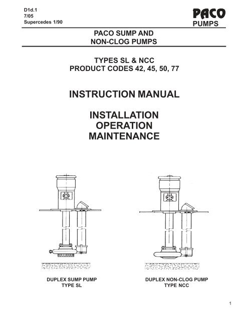
PACO<strong>D1d.1</strong>7/05Supercedes 1/90PUMPSPACO SUMP ANDNON-CLOG PUMPSTYPES <strong>SL</strong> & <strong>NCC</strong>PRODUCT CODES 42, 45, 50, 77INSTRUCTION MANUALINSTALLATIONOPERATIONMAINTENANCEDUPLEX SUMP PUMPTYPE <strong>SL</strong>DUPLEX NON-CLOG PUMPTYPE <strong>NCC</strong>1
PACO<strong>D1d.1</strong>7/05Supercedes 1/90PUMPSI. INSTALLATION-MECHANICALTABLE OF CONTENTSA. Pump Identification ..................................................................................................... 3B. Receiving .................................................................................................................... 3C. Temporary Storage...................................................................................................... 3D. Location....................................................................................................................... 3E. Installation ................................................................................................................... 4F. Piping ........................................................................................................................... 5G. External Wiring ........................................................................................................... 5II.OPERATIONA. Pre-Start Checklist....................................................................................................... 4B. Starting The Pump....................................................................................................... 4C. Pump Shutdown .......................................................................................................... 5III.MAINTENANCEA. Motor Lubrication ......................................................................................................... 5B. Pump Thrust Bearing Lubrication ................................................................................ 6C. Pump Intermediate & Lower Bearing Lubrication ........................................................ 6IV.TROUBLESHOOTINGA. Symptoms....................................................................................................................7B. Possible Causes .......................................................................................................... 7V. WARRANTY ........................................................................................................................ 8VI. SALES AND SERVICE CENTERS..................................................................................... 82
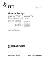
PACO<strong>D1d.1</strong>7/05Supercedes 1/90PUMPSI. INSTALLATIONRead these instructions thoroughly before installingand operating your PACO <strong>Type</strong> ASP and ASP CentrifugalPump. Successful operation depends on carefulattention to the procedures described in Sections 1, 2and 3 of this manual. Keep this instruction manualhandy for future use.A. PUMP IDENTIFICATION• All PACO <strong>Pumps</strong> are identified by Catalog andSerial Numbers. These numbers are stamped onthe pump nameplate (Fig.1a) affixed to each pumpvolute casing, and should be referred to in allcorrespondence with the Company.PACO PUMPSCAT #:STOCK #:SER #: #GPM: TDH: “”“”“”’ IMP.:B. RECEIVINGFIGURE 1aDIA.“””BROOKSHIRE, TEXAS 34014412• Check pumping unit for shortage and damageimmediately upon arrival. Pump accessories whenrequired are packaged in a separate container andshipped with the unit.dations where applicable.D. LOCATION• Sump should be located so that threre is sufficientaccessibility for maintenance and inspection ofpumping unit. Provide a clear space with ampleheadroom for use of a hoist strong enough to liftand remove the unit.• Prior to installation check pump length againstsump depth for proper dimension.E. INSTALLATION• The pumping unit must be freely suspended fromthe sump cover or sole plate. The clearancebetween the pump suction and the bottom of thesump should not be less than one to two times thepump nominal discharge size for optimum performance.• When a suction strainer is included with a suspendedpumping unit a minimum 1/2” clearancebetween the bottom of the strainer and sump flooris recommended.• NOTE: On <strong>SL</strong> type sump pumps inteded for usewithout sump covers, the unit may be mounteddirectly on the sump floor.• Brackets supported from the sump wall may beutilized to retain the unit.• If equipment is damaged in transit, promptly reportthis to the carrier’s agent. Make complete notationson the freight bill to speed satisfactoryadjustment by the carrier.• Unload and handle the unit with a sling. Do not liftunit by eye bolts on the motor!C. TEMPORARY STORAGE• If pump is not to be installed and operated soonafter arrival, store it in a clean, dry area ofmoderate ambient temperature.• Rotate the shaft by hand periodically to coatbearing with lubricant and retard oxidation andcorrosion.• Follow motor manufacturer’s storage recommen-FIGURE 2a: Sump Pump, <strong>Type</strong> <strong>SL</strong>3
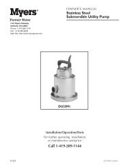
PACO<strong>D1d.1</strong>7/05Supercedes 1/90PUMPSNOTE: REFER TO D1d.3 FOR OPERATION ANDINSTALLATION INSTRUCTIONSOF LIQUID LEVELCONTROLS.• Machined face of motor and bracket should beclean. Install coupling insert in position on pumphalf-coupling (half-couplings should not touch eachother.) Assemble motor, on pump bracket withconduit box located as required. Check couplingalignment with straight-edge.• Refer to appropriate liquid level control instructionsheet for installation and adjustment.• Bolt manhole plate to cover, using gasket forgastight installation.• MICROMETER SHAFT ADJUSTMENT(optional.)To raise shaft and impeller, loosen locknut 9A.Holding the shaft, use a spanner wrench, to turnbearing adapter 26H counter-clockwise untilimpeller makes contact with volute. Then turnbearing adapter clockwise 1/2 to 3/4 of a turn andtighten locknut in position. Check to make certainshaft turns freely. (See Fig. 4a)FIGURE 3a: Non-Clog Pump, <strong>Type</strong> NC• On a gastight installation, install the length ofpacking material on the sump flange. Overlap(side by side) the packing ends four to six inchesfor a complete seal.• Install sump cover over sump basin in a horizontalplane, and position the cover so that pumpsubplate opening(s) will place pump dischargepiping at required position. sump cover should beso positioned that the liquid level control parts arenot placed directly in the parth of the inflow enteringsump. Where this is not possible a baffle isrequired to prevent turbulence of the liquid frominterfering with the proper operation of pump andlevel controls.• If pump bearing have been specially ordered withclean water lubrication, connect the lines, abovesump cover to a clean water supply. If to bemanually operated open valve prior to starting unit.Close valve after unit is shut down. On automaticoperation, insert a solenoid valve, of same voltageas motor, into clean water supply line, and connectto motor or motor starter to open when motor startsand close when motor stops. Fres water supplyshall be minimum of <strong>10</strong> PSIG above pump dischargepressure at 1-2 GPM.4• Remove any shipping supports or coverings on thepump unit before installation.• Install pump and subplate assembly(s) in positionon sump cover, using gasket between subplate andsump cover for a gastight installation. Boltsubplate(s) in place.• Install motor half-coupling on motor (unless themotor is assembled to the unit.)• CAUTION: Do not apply excessive force to installcoupling or motor bearings can be damaged.FIGURE 4a: Typical Micrometer Adjustment
PACO<strong>D1d.1</strong>7/05Supercedes 1/90PUMPSF. PIPING GENERALII.OPERATION• Connect pump discharge and vent piping asrequired by local code.• Install a union or flanges in piping at pump, clear ofsubplate, so complete unit on subplate may beremoved readily.• Discharge piping should be aligned and supportedproperly so that no strain is transmitted properly sothat no strain is transmitted to neither the dischargeconnection nor the pump assembly.• Avoid unnecessary bends and fittings in thedischarge line. Where necessary, use 45° or longsweep90° pipe fittings to decrease friction loss.• To prevent problems associated with dischargebackflow in single or duplex installations, installa check valve in each pump’s discharge line.Install a gate valve between each check valveand the header, to facilitate examination orrepair of check valve, or removal of pumpingunit.G. EXTERNAL WIRING• Motor starter(s), with overload protection, mustbe selected correctly for the motor rating.Follow instructions of motor and starter manufacturersin connecting them and follow wiringdiagram for the liquid level control that is containedin its instruction sheet. Be sure thatmotor overload heaters are properly selected foroperating voltage and amperage.• If atmosphere where motor and/or electricalcontrols are lcoated is damp, appropriateventilation and method of keeping the area is dryis essential• Install electrical wiring in accordance withNational Electrical Code Standards and applicablelocal regulations.• Check final connections by applying power tomotor for an instant, to observe direction of shaftrotation. Shaft must rotate in direction of arrowon pump unit. This is clockwise, looking downon the motor. If rotation is not correct, for threephase motors interchange any two power leadsat top or bottom of motor starter. If motor issingle phase, refer to the motor wiring diagram.A. PRE-START CHECK LISTMake the following inspections before starting yourPACO type <strong>SL</strong> or NC Vertical Pump:Make certain that the motor’s starter nameplate,voltage, phase and frequency matches the powersupply. Check liquid level control wiring diagrams.If motor and pump have been in storage for anextended period, turn shaft by hand to makecertain it rotates freely and the motor bearings areproperly lubricated per maitnenance instructions.Try the motor roation momentarily to be sure it iscorrect according to the arrow on the pump (seeG-4)CAUTION: Never run pump dry. Serious damageto unit can result.Check piping to make sure that all connections aretightly made up. All valves open as required.Make certain level controls are in required position.NOTE: Refer to 1854.615 for operation andinstallation instructions for level controls.B. STARTING THE PUMP• Fill sump with liquid well above pump end, toactuate the high liquid level control.NOTE: Remove all foreign materials from sumpbefore starting pump.)• Start the motor if on manual control, or allow levelcontrol to start if on automatic control. Run pumpthrough the cycles to insure that float switches areworking correclty.• Check all discharge connections above sumpcover for liquid leaks.• Check and record the voltage, the amperers perphase, and the kilowatts if a wattmeter is available.If voltage is above <strong>10</strong>% or below <strong>10</strong>% themotor nameplate voltage, shut unit down andcheck wiring connections. If wiring connectionsare proper, notify the power company.5
PACO<strong>D1d.1</strong>7/05Supercedes 1/90PUMPS• A motor will operate satisfactorily with a voltagevariation not exceeding <strong>10</strong>% above or below therating specified on the motor nameplate. Voltagesabove these limits will cause heavy magneticsatuaration of the motor winiding and indicate highamperage.• Being operated by generator, the power supplyshould not exceed 5% above or below the motorfrequency (Hz) rating, for proper performance.C. PUMP SHUTDOWN• Cut power to motor(s) or allow low level control toshut unit down.• If a unit is shut down and the possibility of freezingexists, disconnect the discharge line and takenecessary precautions to prevent freezing withinthe sump.III. MAINTENANCEA. MOTOR LUBRICATION• If the motor is not equipped with grease plugs orgrease fittings at its ends (check under the topcanopy) it has “sealed bearings”, and does notrequire periodic lubrication.• If the motor has provision for lubrication of itsbearings (grease plugs or grease fittings) followlubrication instructions furnished with motors.• If lubrication instructions do not accompany motor,following tables give frequency of greasing andrecommended types of grease for motor bearings.RECOMMENDED FREQUENCY OF LUBRICATIONMOTOR OPERATING CONDITIONSHP STANDARD SEVERE EXTREME1/3 7-1/2 3 yrs. 1 yr. 6 mos.<strong>10</strong>-40 1-3 yrs. 1/2 1 yr. 3 mos.50 & UP 1 yr. 6 mos. 3 mos.TABLE 5aB. PUMP THRUST BEARING LUBRICATION• These bearings are integrally sealed and lubricatedfor life. No further lubrication required.Standard Operating Conditions: 8 hours a day,clean atmosphere, motor not overloaded, <strong>10</strong>0° F. max.ambient temperature. Severe Operating Conditions:24 hours a day, <strong>10</strong>0° F. to 150° F. ambienttemperature; dirty or dusty. Extreme OperatingConditions: Very heavy dust or dirt.RECOMMENDED TYPES OF GREASE FORBALL BEARINGSManufacturerLubricantExxonAndok BStandard Oil of California Chevron BRB2Shell Oil co.Alvania EP2Texaco, Inc. Regal Starfak #2Mobil Oil Co. Mobilux Grease #2TABLE 6aC. PUMP INTERMEDIATE AND LOWERBEARING LUBRICATION• Self-lubricating intermediate bearing bushings arenormally furnished. For those pumps furnishedwith grease lines to intertmediate bearings, inject alubricant selected from Table IIIb into grease-linefitting (s). Lubricate daily for continuously operatingpumps to once a month for intermittent pumpoperation.• Lower bearing normally is lubricated by the liquidpumped. If lower bearing has been speciallyordered with a grease line, lubricate per C-1.• If pump bearings have been specially ordered withclean water lubrication, connect the lines, abovesump cover to a clean water supply. If to bemanually operated open valve prior to starting unit.Close valve after unit is shut down. On automaticoperation, insert a solenoid valve, of same voltageas motor, into clean water supply line, and connectto motor or motor starter to open when motor startsand close when motor stops. Fresh water supplyshall be a minimum of <strong>10</strong> PSIG above pumpdischarge pressure at 1-2 GPM.• IMPORTANT: Most codes do not permit crossconnectionof water supply for a sump pumpbearing to a potable water supply. A PACO WaterSeal Unit should be installed. This is a small pumping unit with tank and water float valve, providingan air gap between the water source and the wateruse. It can be wired to start and stop with the pumpmotor.6
PACO<strong>D1d.1</strong>7/05Supercedes 1/90PUMPSof quotation. Seller shall not be liable for any nonperformance, loss, damage, or delay due to war, riots, fire, flood, strikesor other labor difficulty, governmental actions, acts of God, acts of the Buyer or its customer, delays in transportation,inability to obtain necessary labor or materials from usual sources, or other causes beyond the reasonable control ofSeller. In the event of delay in performance due to any such cause, the date of delivery or time for completion will beextended to reflect the length of time lost by reason of such delay. Seller shall not be liable for any loss or damage toBuyer resulting from any delay in delivery.SECTION <strong>10</strong>: WARRANTYSeller warrants that the equipment or services supplied will be free from defects in material, and workmanship for aperiod of 12 months from the date of initial operation of the equipment, or 18 months from the date of shipment,whichever shall first occur. In the case of spare or replacement parts manufactured by Seller, the warranty period shall befor a period of six months from shipment. Repairs shall be warranted for 12 months or, if the repair is performed underthis warranty, for the remainder of the original warranty period, whichever is less. Buyer shall report any claimed defect inwriting to Seller immediately upon discovery and in any event, within the warranty period. Seller shall, at its sole option,repair the equipment or furnish replacement equipment or parts thereof, at the original delivery point. Seller shall not beliable for costs of removal, reinstallation, or gaining access. If Buyer or others repair, replace, or adjust equipment orparts without Seller’s prior written approval, Seller is relieved of any further obligation to Buyer under this section withrespect to such equipment or parts. The repair or replacement of the equipment or spare or replacement parts by Sellerunder this section shall constitute Seller’s sole obligation and Buyer’s sole and exclusive remedy for all claims ofdefects. SELLER MAKES NO OTHER WARRANTY OR REPRESENTATION OF ANY KIND WITH RESPECT TO THEEQUIPMENT OR SERVICES OTHER THAN AS SPECIFIED IN THIS SECTION <strong>10</strong>. ALL OTHER WARRANTIES, EXPRESSOR IMPLIED, INCLUDING BUT NOT LIMITED TO, THE IMPLIED WARRANTIES OF MERCHANTABILITY AND FITNESS FORA PARTICULAR PURPOSE, ARE HEREBY DISCLAIMED.For purposes of this Section, the equipment warranted shall not include equipment, parts, and work not manufactured orperformed by Seller. With respect to such equipment, parts, or work, Seller’s only obligation shall be to assign to Buyerany warranty provided to Seller by the manufacturer or supplier providing such equipment, parts or work.No equipment furnished by Seller shall be deemed to be defective by reason of normal wear and tear, failure to resisterosive or corrosive action of any fluid or gas, Buyer’s failure to properly store, install, operate or maintain the equipmentin accordance with good industry practices or specific recommendations of Seller, or Buyer’s failure to provide completeand accurate information to Seller concerning the operational application of the equipment.SECTION 11: TECHNICAL DOCUMENTSTechnical documents furnished by Seller to Buyer, such as drawings, descriptions, designs and the like, shall bedeemed provided to Buyer on a confidential basis, shall remain Seller’s exclusive property, shall not be provided in anyway to third parties, and shall only be used by Buyer for purposes of installation, operation and maintenance. Technicaldocuments submitted in connection with a Quotation that does not result in a Purchase Order shall be returned to Sellerupon request.SECTION 12: LIMITATION OF LIABILITYSeller shall in no event be liable for any consequential, incidental, indirect, special or punitive damages arising out of theContract, or out of any breach of any of its obligations hereunder, or out of any defect in, or failure of, or malfunction of theequipment, including but not limited to, claims based upon loss of use, lost profits or revenue, interest, lost goodwill,work stoppage, impairment of other equipment, environmental damage, nuclear incident, loss by reason of shutdown ornonoperation, increased expenses of operation, cost of purchase of replacement power or claims of Buyer or customersof Buyer for service interruption whether or not such loss or damage is based on contract, tort (including negligence andstrict liability) or otherwise.Seller’s maximum liability under this Contract shall not exceed the Purchase Order amount of the equipment or portionthereof upon which such liability is based. All such liability shall terminate upon the expiration of the warranty period, if notsooner terminated.SECTION 13: THIS COMPANY IS AN EQUAL OPPORTUNITY EMPLOYERThis agreement incorporates by reference applicable provisions and requirements of Executive Order 11246 and FARSection 52.222-26 (covering race, color, religion, sex and national origin); the Vietnam Era Veterans ReadjustmentAssistance Act of 1974 and FAR Section 52.222-35 (covering special disabled and Vietnam era veterans); and theRehabilitation Act of 1973 and FAR Section 52.222-36 (covering handicapped individuals). By acceptance of thisagreement Buyer certifies that it does not and will not maintain any facilities in a segregated manner, or permit itsemployees to perform their services at any location under its control where segregated facilities are maintained, andfurther that appropriate physical facilities are maintained for both sexes. Buyer agrees that it will obtain a similarcertificate prior to award of any nonexempt lower-tier subcontracts.SECTION 14: LAW AND ARBITRATIONThe Contract shall be governed by the law of the State of Texas. Any disputes arising out of this Contract shall be resolvedby informal mediation in any manner that the parties may agree within 45 days of written request for mediation by oneparty to the other. Any dispute that cannot be resolved through mediation shall be resolved by binding arbitrationconducted in English in Portland, Oregon under the Commercial Rules of the American Arbitration Association except asotherwise provided in this Section. The arbitration shall be conducted by three arbitrators chosen in accordance with saidRules. The arbitrators are not entitled to award damages in excess of compensatory damages. Judgment upon theaward may be entered in any court having jurisdiction.9
PACO<strong>D1d.1</strong>7/05Supercedes 1/90PUMPSCheck our worldwide offices atwww.paco-pumps.com<strong>D1d.1</strong> Copyright © Grundfos CBS Inc.<strong>10</strong>