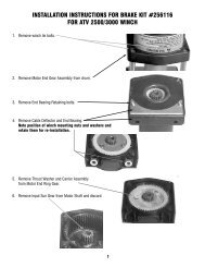

Create successful ePaper yourself
Turn your PDF publications into a flip-book with our unique Google optimized e-Paper software.
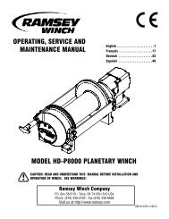
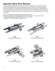
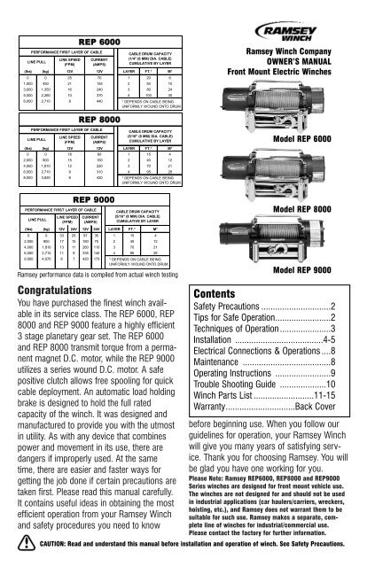
REP 6000PERFORMANCE FIRST LAYER OF CABLECABLE DRUM CAPACITY(1/4" (6 MM) DIA. CABLE)LINE SPEED CURRENTLINE PULLCUMULATIVE BY LAYER(FPM)(AMPS)(lbs) (kg) 12V 12V LAYER FT.* M*0 0 25 70 1 20 61,000 450 21 155 2 50 153,000 1,350 16 240 3 80 245,000 2,260 10 370 4 100 306,000 2,710 8 440* DEPENDS ON CABLE BEINGUNIFORMLY WOUND ONTO DRUM.<strong>Ramsey</strong> <strong>Winch</strong> CompanyOWNER’S MANUALFront Mount Electric <strong>Winch</strong>esREP 8000PERFORMANCE FIRST LAYER OF CABLELINE SPEED CURRENTLINE PULL(FPM)(AMPS)CABLE DRUM CAPACITY(5/16" (8 MM) DIA. CABLE)CUMULATIVE BY LAYERModel REP 6000(lbs) (kg) 12V 12V LAYER FT.* M*0 0 18 60 1 15 42,000 900 15 150 2 40 124,000 1,810 12 220 3 70 216,000 2,710 9 310 4 95 288,000 3,620 6 420 * DEPENDS ON CABLE BEINGUNIFORMLY WOUND ONTO DRUM.REP 9000PERFORMANCE FIRST LAYER OF CABLECABLE DRUM CAPACITYLINE SPEED CURRENT (5/16" (8 MM) DIA. CABLE)LINE PULL(FPM) (AMPS)CUMULATIVE BY LAYERModel REP 8000(lbs) (kg) 12V 24V 12V 24V LAYER FT.* M*0 0 33 25 97 35 1 15 42,000 900 17 15 180 75 2 40 124,000 1,810 13 11 260 110 3 70 216,000 2,710 11 9 335 140 4 95 289,000 4,070 8 7 420 175 * DEPENDS ON BEINGCABLEUNIFORMLY WOUND ONTO DRUM.<strong>Ramsey</strong> performance data is compiled from actual winch testing<strong>Congratulations</strong>You have purchased the finest winch availablein its service class. The REP 6000, REP8000 and REP 9000 feature a highly efficient3 stage planetary gear set. The REP 6000and REP 8000 transmit torque from a permanentmagnet D.C. motor, while the REP 9000utilizes a series wound D.C. motor. A safepositive clutch allows free spooling for quickcable deployment. An automatic load holdingbrake is designed to hold the full ratedcapacity of the winch. It was designed andmanufactured to provide you with the utmostin utility. As with any device that combinespower and movement in its use, there aredangers if improperly used. At the sametime, there are easier and faster ways forgetting the job done if certain precautions aretaken first. Please read this manual carefully.It contains useful ideas in obtaining the mostefficient operation from your <strong>Ramsey</strong> <strong>Winch</strong>and safety procedures you need to knowModel REP 9000<strong>Contents</strong>Safety Precautions ..............................2Tips for Safe Operation........................2Techniques of Operation ......................3Installation ......................................4-5Electrical Connections & Operations ....8Maintenance ......................................8Operating Instructions ........................9Trouble Shooting Guide ....................10<strong>Winch</strong> Parts List ..........................11-15Warranty..............................Back Coverbefore beginning use. When you follow ourguidelines for operation, your <strong>Ramsey</strong> <strong>Winch</strong>will give you many years of satisfying service.Thank you for choosing <strong>Ramsey</strong>. You willbe glad you have one working for you.Please Note: <strong>Ramsey</strong> REP6000, REP8000 and REP9000Series winches are designed for front mount vehicle use.The winches are not designed for and should not be usedin industrial applications (car haulers/carriers, wreckers,hoisting, etc.), and <strong>Ramsey</strong> does not warrant them to besuitable for such use. <strong>Ramsey</strong> makes a separate, completeline of winches for industrial/commercial use.Please contact the factory for further information.CAUTION: Read and understand this manual before installation and operation of winch. See Safety Precautions.
Safety Precautions To GuardAgainst Possible Injury…A minimum of five wraps of cable around thedrum barrel is necessary to hold the rated load.Cable clamp in not designed to hold the load.A. Keep yourself and others a safe distance tothe side of the cable when pulling under load.B. Don't step over a cable, or near a cable underload.C. Use supplied hook strap when handling hookfor spooling wire rope.D. Don't move the vehicle to pull a load on thewinch cable. This could result in cable breakage.E. Use a heavy rag or gloves to protect handsfrom burrs when handling winch cable.F. Apply blocks to wheels when vehicle is on anincline.G. <strong>Winch</strong> clutch should be disengaged whenwinch is not in use and fully engaged when inuse.H. Modification, alteration or deviation to thewinch should only be made by <strong>Ramsey</strong> <strong>Winch</strong>Company.I. Keep the duration of your pulls as short aspossible. If the motor becomes uncomfortablyhot to the touch, stop and let it cool for a fewminutes. Do not pull more than one minute ator near rated load. Do not maintain power tothe winch if the motor stalls. Electric winchesare for intermittent usage and should not usedin constant duty applications.J. Disconnect the remote control switch from thewinch when not in use. A <strong>Ramsey</strong> Part No.282053 safety on-off switch in your vehicle isrecommended.K. Note: Do not use winch in hoisting applicationsdue to required hoist safety factors andfeatures.L. Do not exceed maximum line pull ratingsshown in tables. Shock loads must notexceed these ratings.M. To respool correctly, it is necessary to keep aslight load on the cable. This is accomplishedby (wearing gloves) holding the cable withone hand and the remote control switch withthe other, starting as far back and in the centeras you can, walking up keeping load onthe cable as the winch is powered in. Do notallow the cable to slip through your hand anddo not approach the winch too closely. Turnoff the winch and repeat the procedure until allthe cable except a few feet is in. Disconnectthe remote control switch and finish spoolingin cable by rotating the drum by hand withclutch disengaged. On hidden winches, spoolin cable under power using supplied hookstrap.Tips for Safe OperationDon't underestimate the potential danger in winchingoperations. Neither should you fear them. Dolearn the basic dangers and avoid them.The uneven spooling of cable, while pulling aload, is not a problem, unless there is cable pileupon one end of drum. If this happens, reversethe winch to relieve the load and move youranchor point further to the center of the vehicle.After the job is done you can unspool and rewindfor a neat lay of the cable.Store the remote control switch inside your vehiclewhere it will not become damaged. Inspect itbefore you plug it in.When ready to begin spooling in, plug in remotecontrol switch with clutch disengaged. Do notengage clutch with motor running.Never connect the hook back to the cable. Thiscauses cable damage. Always use a sling orchain of suitable strength as shown in the illustrations.Observe your winch while winching, if possible,while standing at a safe distance. If you use vehicledrive to assist, stop and get out every few feetto assure the cable is not piling up in one corner.Jamming cable can break your winch.Do not attach tow hooks to winch mounting apparatus.They must attach to vehicle frame.2
When double lining during stationary winching,the winch hook should be attached to the chassisof the vehicle.Since the greatest pulling power is achieved onthe innermost layer of your winch, it is desirableto pull off as much line as you can for heavy pulls(remember, you must leave 5 wraps min. on thedrum). If this is not practical, use a snatch blockand double line arrangement (see illustration).Neat, tight spooling avoids cable binding, which iscaused when a load is applied and the cable ispinched between two others. If this happens,alternately power the winch in and out a few inches.Do not attempt to work a bound cable underload; free by hand.For basic self-recovery, anchor to a tree or heavy rock.When anchoring to a tree, always use a tree trunk protector.Stakes driven in solid earth and chained together make agood anchor point for self-recovery when no solid anchorpoint is available.<strong>Winch</strong>es equipped with cable guide fairleads can pullfrom several directions. Pull from an angle only tostraighten up the vehicle-otherwise you can damagestructural members or other parts of your vehicle andcause excess cable buildup on one end of the winch drum.For a direct pull of 2000 lbs., hitch truck to a tree or solidanchor, and take out of gear.Techniques of OperationThe best way to get acquainted with how yourwinch operates is to make a few test runs beforeyou actually need to use it. Plan your test inadvance. Remember you hear your winch as wellas see it operate. Get to recognize the sound oflight steady pull, a heavy pull, and sounds causedby load jerking or shifting. Soon you will gainconfidence in operating your winch and its usewill become second nature with you.Your winch will not only pull your vehicle up orease your vehicle down a steep grade, it will alsopull another vehicle or a load while your vehicle isanchored in a stationary position. The followingsketches show you a few techniques.When pulling a heavy load, place a blanket, jacketor tarpaulin over the cable five or six feet from thehook. It will slow the snap back in the event of abroken cable. Also open the vehicle hood foradditional protection.For a solid anchor, bury a log with earth or sand or placeit in a deep ravine.To double the pull, use 2-part line with snatch block andtie off to chassis. Take out of gear.Use the vehicle wheel power to help the winch,but don't overtake the winch line. Plan your pull.You can't always hook up and pull out in one step.Examine all the areas for anchoring possibilitiesas well as leverage situations, direction and goal.3
InstallationThe winches shown in this owner's manual aresolely and exclusively designed for vehicle mounted,non-industrial applications. All other applicationswill void warranty.Note: For specific bull-bar applications, the shifterlever on the winch may need to be repositioned.Refer to pages 6-7 for instructions in how to dothis.It is very important that the winch be mounted ona flat surface so that the three major sections (themotor end, the cable drum and the gear housingend) are properly aligned. It is recommended that<strong>Ramsey</strong> kits be used to mount the winch. Theyare designed to align the winch and distribute upto the full rated load evenly, to avoid possibledamage to the winch or vehicle. Note: If recommendedmounting is not used, a kit of equaldesign must be used.Also available for mounting the REP winches arewinch mounting channels, short length (23.63")#408052 (black), medium length (30.00")#408120 (black) and long length (36.00")#408101 (black). It is recommended that a<strong>Ramsey</strong> mounting channel be used in all non-<strong>Ramsey</strong> mountings.Note: See the following separate sections forattaching the wiring to the motor and solenoid forthe REP 6000/8000, REP 9000 12V, and REP9000 24V models. The combined installationinstructions resume on the following page.clamp to attach solenoid assembly to winchmotor (see FIGURE 2). Position solenoid at abouta 45° angle for clearance of lower winch guardtube of kit. TIGHTEN CLAMP SECURELY.FIGURE 2REP 9000 12VWhen mounting winch, connect labeled motorleads coming from solenoid assembly to appropriatelymarked motor terminals. TIGHTEN NUTSON MOTOR TERMINALS SECURELY (see FIGURE3). Attach solenoid ground wire to grounding boltlocated at bottom of motor (Battery ground wire isalready installed to grounding bolt on motor.)Use solenoid clamp, as shown in FIGURE 2, tosecure solenoid assembly to winch motor. Ifinstalling in combo mounting kit, position at abouta 45° angle for clearance of lower winch guardtube in kit. Be sure that clamp is clear of motorterminals at bottom of motor. TIGHTEN CLAMPSECURELY.REP 6000/8000When mounting winch, attach solenoid wires tomotor terminals at end of motor. TIGHTEN NUTSON MOTOR TERMINALS SECURELY (see FIGURE1). Attach solenoid to mounting holes at end oflong channel (see FIGURE 1) or use solenoidFIGURE 3FIGURE 14
REP 9000 24VWhen mounting winch, connect labeled motorleads coming from solenoid assembly to appropriatelymarked motor terminals. TIGHTEN NUTSON MOTOR TERMINALS. Attach solenoid groundto #10 Capscrew located on vertical surface ofmotor end bearing (See FIGURE 4). Use solenoidclamp, as shown in FIGURE 2, to secure solenoidassembly to winch motor. If installing in combomounting kit, position at about a 45° angle forclearance of lower winch guard tube in kit. Besure that clamp is clear of motor terminals at bottomof motor. TIGHTEN CLAMP SECURELY.Hole forSolenoidGround WireBoltAttach fairlead to channel using hardwarefurnished with winch (see FIG-URE 5). Attach winch to channel.Place (4) flat washers and nuts intopockets of winch mounting feet andthread capscrews with lock washersthrough mounting holes in channel andinto hardware in winch feet.Substitution of attaching hardwareitems (bolts, nuts or washers) differentfrom those supplied with your winchand mounting kit can lead to failurecausing damage or serious injury (useSAE grade 5 bolts or better and torqueto 34 ft. lbs.)Place end of drum cable through fairleadand attach cable hook. Use clevispin and cotter pin (see FIGURE 5).MotorTerminalsFIGURE 4FIGURE 55
Repositioning Shifter for Specific Bull Bar ApplicationsNote: The shifter is positioned correctly for most applications. It will only need to be repositioned asnecessary for specific bull bar applications.Refer to the Parts List and Exploded Parts Diagram for your specific winch elsewhere in this owner’smanual.1. Position winch as shown in Figure 6. Remove screws from tiebars. You may be able to loosen thescrews at the motor end without removing them. Pull the Gear Housing assembly from the drum andshaft and set it down on the work bench with the Gear Housing Cover up. Remove the drum bushingfrom the Gear Housing assembly or the end of the drum. Set aside.2. Remove (6) capscrewsfrom the Gear HousingCover. Holding the GearHousing Cover over theGear Housing assembly,flip it over and set it on theworkbench.FIGURE 63. Gently lift the Gear Housingassembly, working the gears,bushings, etc. that are inside theGear Housing out so that they areleft stacked on the workbench.See Figure 8.4. Turn the Gear Housing assemblyover and set on workbench.Remove the Retainer (item #37)by removing six capscrews (item#21) from Gear End Bearing(item 13). Once the retainer isremoved, the Ring Gear (item#10), Cam Ring (item #36), andLocking Ring (item #34) can belifted off the end bearing.Remove the six springs (item#38) from the end bearing.FIGURE 76FIGURE 8
5. Determine position shifter knob needs tobe for your application. Note: Shifterknob cannot be positioned too low or itwill interfere with the feet on the GearEnd Bearing (see Range of Position inFigure 9).6. To position the shifter knob, place lockingring in end bearing with stop postapproximately 180° from where shifterknob needs to be positioned. Place camring over locking ring in proper positionand confirm that shifter knob will movefrom engaged to disengaged positionwithout interference. Mark position of FIGURE 9stop post on end bearing.7. Remove cam ring and locking ring from end bearing. Insert springs (item #38) into end bearing.When you replace the locking ring (item #34) over the springs, be sure the springs compress downinto their recesses, and don’t bend sideways.8. Reassemble Gear Housing as shown in Figure 7. Make sure locking ring is positioned with stoppost at marked location. The capscrews (item #38) for the retainer should be tightened to 40-45 inlbs.Do not over-tighten.9. Place Gear Housing over the stacked gears, etc. that you removed in step 3. Gently work the housingover the stack, turning it as needed to mesh the planetary gears with the ring gear in the housing.Once they are all in the housing, flip the assembly over. Align the Gear Housing Cover and gasketwith the holes in the ring gear. Replace the (6) capscrews that hold the Gear Housing Cover ontothe Gear Housing. Tighten securely.10. Move the Shifter to the Disengaged position.11. Turn the Gear Housing over and set it on thework bench with the Gear Housing Coverdown. See Figure 10.12. Install the drum bushing into the GearHousing, confirming that the slot in the bushingis aligned with the key in the end bearing.Pick up the rest of the winch (drum andmotor end), and holding the drum, lower thewinch onto the gear end. Stab the shaft intothe gear end--you may need to turn the drumslightly to get the shaft to go all the way in.13. Place the tiebars on the motor end and gearend and fasten using (4) screws. Tightensecurely.FIGURE 1014. Once the winch is reassembled, turn it sothat it is sitting on its feet. Confirm that the cable will freespool when the shifter is in theDisengaged position. Connect up the winch temporarily and confirm that the cable spools when theshifter is in the Engaged position.7
FIGURE 11Electrical Connections andOperationsFor normal self-recovery work, your existing electricalsystem is adequate. Your battery must bekept in good condition. A fully charged batteryand proper connections are essential. Run thevehicle engine during winching operations to keepbattery charged.REP-6000/REP-8000/REP 9000 12V ElectricalConnectionsRoute red and black battery cables up to battery.CAUTION: BE SURE BATTERY CABLES ARE NOTDRAWN TAUT ACROSS ANY SURFACES WHICHCOULD POSSIBLY DAMAGE THEM. Connect redcable to positive (+) battery terminal and blackcable to negative (-) terminal.REP-9000 24V Electrical ConnectionsRoute battery cable up to battery. CAUTION: BESURE BATTERY CABLES ARE NOT DRAWN TAUTACROSS ANY SURFACES WHICH COULD POSSI-BLY DAMAGE THEM. Connect red cable to positive(+) battery terminal (see Figure 3). Connectblack ground cable to negative (-) terminal of batteryand to winch mounting bolt on motor end ofwinch (see Figure 6 on following page).The remote control switch is waterproof. It haspush button stations on either side. It is designedthis way to prevent quick winch reversals, whichlead to solenoid failure. Make sure the motor hasstopped fully before reversing. To actuate winchsimply plug remote control switch into receptaclein black solenoid cover of winch. Run winch forwardand reverse to check connection and todetermine winch operating directions. Snapappropriate "IN" and "OUT" disc into proper thumbcavity. The switch is also color coded to aid youin not having to guess at the direction your winchwill run. DO NOT LEAVE SWITCH PLUGGED INWHEN WINCH IS NOT IN USE.Corrosion on electrical connections will reduceperformance or may cause a short. Clean all connectionsespecially in remote control switch andreceptacle. In salty environments use a siliconesealer to protect from corrosion.MaintenanceAll moving parts in the winch are permanentlylubricated with high temperature lithium grease atthe time of assembly. Under normal conditionsfactory lubrication will suffice. Lubricate cableperiodically using light penetrating oil. Inspect forbroken strands and replace if necessary with<strong>Ramsey</strong> part number listed in Parts List. If thecable becomes worn or damaged, it must bereplaced.Unwind the new cable by rolling it out along theground, to prevent kinking. Remove old cable andobserve the manner in which it is attached to thecable drum flange.Before installing the new cable assembly, makesure end of cable is squarely cut and wrappedwith tape to prevent fraying. Form a short 90°bend (approximately ½") on end of the cable.Position the cable drum so that the large 13/32"diameter hole in the motor end drum flange isapproximately on the top. Insert the bent end ofcable into the 13/32" hole in the drum flange andthen carefully run the winch in the "reel in" directionapproximately ¾ revolution until the ¼" diam-8
eter threaded hole in the drum flange is on top.Secure the cable to the drum flange using cableanchor and capscrew shown in the parts drawing.Securely tighten the capscrew, but do not overtighten.Wind 5 wraps of cable onto the drum. <strong>Winch</strong> onthe rest of the cable by pulling in a light load tokeep the tension constant. Allow the cable toswivel by using a length of chain or a blockbetween the cable hook and the load.Operating InstructionsThe winch clutch allows rapid unspooling of thewire rope for hooking onto the load or anchorpoint. The clutch is operated by the shifter tablocated on the gear-housing end of the winch asfollows:1.To disengage the clutch, move the clutch shiftertab to the "OUT" position. Wire rope may nowbe free-spooled off the drum.2.To engage the clutch, move the clutch shiftertab into the "IN" position. The winch is nowready for pulling.9
<strong>Ramsey</strong> Electric <strong>Winch</strong>es Troubleshooting GuideCONDITIONPOSSIBLE CAUSECORRECTIONMOTOR RUNS IN ONLY ONEDIRECTION(1) Defective solenoid or stuck solenoid(1) Jar solenoid to free contacts. Check by applying 12volts to coil terminal (it should make an audible click whenenergized)MOTOR RUNS EXTREMELYHOTMOTOR RUNS, BUT WITHINSUFFICIENT POWER, ORWITH LOW LINE SPEEDMOTOR RUNS, BUT DRUMDOES NOT TURN(2) Defective remote control switch(1) Long period of operation(1) Insufficient battery(2) Bad connection(3) Insufficient charging system(1) Clutch not engaged(2) Disengage winch clutch, remove remote control switchplug from the socket and jump pins at 8 and 4 o’clock.Motor should run. Jump pins at 8 and 10 o’clock. Motorshould run(1) Cooling-off periods are essential to prevent overheating(1) Check battery terminal voltage under load. If 10 volts orless, replace or parallel another battery to it(2) Check battery cables for corrosion; clean and grease(3) Replace with larger capacity charging system(1) If clutch engaged but symptom still exists, it will benecessary to disassemble winch to determine cause andrepairMOTOR WILL NOT OPERATE(1) Defective solenoid or stuck solenoid(2) Defective remote control switch(1) Jar solenoid to free contacts. Check solenoid by applying12 volts to coil terminal (it should make an audible clickwhen energized)(2) Disengage winch clutch, remove remote control switchplug from the socket and jump pins at 8 and 4 o’clock.Motor should run. Jump pins at 8 and 10 o’clock. Motorshould run.MOTOR WATER DAMAGED(3) Defective motor(4) Loose connections(1) Submerged in water or water fromhigh pressure car wash(3) If solenoids operate, check for voltage at armature post;replace motor(4) Tighten connections on bottom side of hood and onmotor(1) Allow to drain and dry thoroughly, then run motor withoutload in short bursts to dry windings.CABLE DRUM WILL NOTFREESPOOL OR IS DIFFICULTTO FREESPOOL(1) Clutch not disengaged(2) <strong>Winch</strong> not mounted squarely causingend bearing to bind drum(1) Check clutch operation according to nameplate. Makesure clutch shifter knob is fully at “OUT” position.(2) Check mounting to see that installation instructions onpage 4 have been followed.(3) Some or all of the (6) 414861 flathead capscrews attaching the 479007ring gear retainer are too tight(3) Remove the gear housing cover, 413018, and all gearsfrom inside the gear housing. Disengage the clutch andcheck to see that the ring gear will rotate by hand. If it willnot, using a hex (allen) wrench, slightly loosen all the capscrewsand then snugly re-tighten them in cross-cross pattern,but do not over tighten. The ring gear must rotate byhand. Re-assemble the winch.10
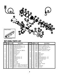
REP 6000Hawse FairleadIncluded with: REP 6000 HReplacement Kit #251152Roller FairleadReplacement Kit #251183Included with: REP 6000 RREP 6000 PARTS LISTItemItemQty. Parts No.DescriptionQty. Parts No.No.No.Description1 1 247009 Gear Carrier Ass’y.—Input 20 6 416273 Screw #6—32NCx3/8 Lg. Fil. Hd.2 1 247007 Gear Carrier Ass’y—Intermediate 21 4 418018 Nut 1/4—20NC Hx. Reg. Elastic Stop3 1 247008 Gear Carrier Ass’y—Output 22 4 418035 Nut 3/8—16NC Hx. Reg. Z/P4 1 251110 Switch Ass’y 23 4 418177 Lockwasher 3/8 ID Med. Sect. Plated5 1 251228 Cable Assembly-100’ 1/4” (6MM) Dia. 24 4 418181 Washer—Flat 3/8 ID S.A.E., Plated6 1 278154 Solenoid Ass’y 25 1 424023 Clamp7 1 296181 Brake/Shaft Ass’y 26 1 442207 Gasket8 1 332128 Drum—Cable 27 1 444048 Gear—Output, Sun9 1 334143 Gear—Ring 28 1 448071 Cable Anchor10 1 334147 Gear—Intermediate, Sun 29 2 448049 Tie Bar11 1 334154 Gear—Input, Sun 30 1 458109 Motor/End Bearing Ass’y.12 1 338249 End Bearing 31 1 470053 Roll Pin 1/8 Dia. x 3/813 2 412056 Bushing—Drum 32 1 477002 Locking Ring14 1 412061 Bushing—Shaft 33 1 477003 Cam Ring15 1 413018 Cover—Gear Housing 34 2 477004 Ring—Half16 4 414316 Capscrew 3/8—16NCx1-1/4Lg.Hx.Hd.Gr.5,Z/P 35 1 479007 Retainer—Ring Gear17 4 414829 Capscrew 1/4—20NCx1 Lg. Soc. Button Hd. 36 6 494077 Spring18 1 414830 Capscrew 1/4—20NCx3/8 Lg. Soc. Button Hd. 37 3 518020 Thrust Washer19 6 414861 Capscrew 1/4—20NCx3/4 Lg. Flat Hd. Soc. NYLOK 38 1 518027 Thrust Disc11
REP 8000Hawse FairleadIncluded with: REP 8000 HReplacement Kit #251152Roller FairleadReplacement Kit #251183Included with: REP 8000 RREP 8000 PARTS LISTItemNo.Qty. Parts No.Description12ItemQty. Parts No.No.Description1 1 247004 Gear Carrier Ass’y.—Input 20 6 416273 Screw #6—32NCx3/8 Lg. Fil. Hd.2 1 247007 Gear Carrier Ass’y—Intermediate 21 4 418018 Nut 1/4—20NC Hx. Reg. Elastic Stop3 1 247008 Gear Carrier Ass’y—Output 22 4 418035 Nut 3/8—16NC Hx. Reg. Z/P4 1 251110 Switch Ass’y 23 4 418177 Lockwasher 3/8 ID Med. Sect. Plated5 1 251118 Cable Assembly-95’ 5/16” (8MM) Dia. 24 4 418181 Washer—Flat 3/8 ID S.A.E., Plated6 1 278155 Solenoid Ass’y 25 1 424023 Clamp7 1 296181 Brake/Shaft Ass’y 26 1 442207 Gasket8 1 332128 Drum—Cable 27 1 444048 Gear—Output, Sun9 1 334143 Gear—Ring 28 1 448046 Cable Anchor10 1 334147 Gear—Intermediate, Sun 29 2 448049 Tie Bar11 1 334153 Gear—Input, Sun 30 1 458109 Motor/End Bearing Ass’y.12 1 338249 End Bearing 31 1 470053 Roll Pin 1/8 Dia. x 3/813 2 412056 Bushing—Drum 32 1 477002 Locking Ring14 1 412061 Bushing—Shaft 33 1 477003 Cam Ring15 1 413018 Cover—Gear Housing 34 2 477004 Ring—Half16 4 414316 Capscrew 3/8—16NCx1-1/4Lg.Hx.Hd.Gr.5,Z/P 35 1 479007 Retainer—Ring Gear17 4 414829 Capscrew 1/4—20NCx1 Lg. Soc. Button Hd. 36 6 494077 Spring18 1 414830 Capscrew 1/4—20NCx3/8 Lg. Soc. Button Hd. 37 3 518020 Thrust Washer19 6 414861 Capscrew 1/4—20NCx3/4 Lg. Flat Hd. Soc. NYLOK 38 1 518027 Thrust Disc
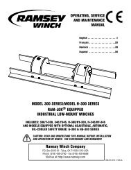
REP 9000REP 9000 PARTS LISTItemItemQty. Parts No.DescriptionQty. Parts No.No.No.Description1 1 247009 Gear Carrier Ass’y.—Input 23 4 418035 Nut 3/8—16NC Hx. Reg. Z/P2 1 247022 Gear Carrier Ass’y—Intermediate 24 4 418040 Nut 3/8—24NC Hx. Reg. Z/P3 1 247023 Gear Carrier Ass’y—Output 25 5 418177 Lockwasher 3/8 Med. Sect. Z/P 12V4 1 278158 Solenoid Ass’y—12V 8 418177 Lockwasher 3/8 Med. Sect. Z/P 24V1 278096 Solenoid Ass’y—24V 26 5 418181 Washer—Flat 3/8 ID S.A.E. Z/P5 1 251110 Switch Ass’y 27 1 424023 Clamp6 1 296181 Brake/Shaft Ass’y—12V 28 1 442208 Gasket—Cover1 296385 Brake/Shaft Ass’y—24V 29 1 444077 Gear—Ring, Input7 1 328138 Cover—Gear Housing 30 1 448046 Cable Anchor8 1 332193 Drum—Cable 31 2 448049 Tie Bar9 1 334154 Gear—Input Sun 32 1 450001 Key—24V.10 1 334147 Gear—Intermediate Sun 33 1 458114 Motor—Electric 12V11 1 334170 Gear—Output Sun 1 458005 Motor—Electric 24V12 1 334171 Gear—Ring, Output 34 1 470053 Roll Pin 1/8 Dia. x 3/8 Lg.13 1 338332 End Bearing 35 1 477002 Locking Ring14 1 296534 End Bearing—Motor—12V 36 1 477003 Cam Ring1 338282 End Bearing—Motor—24V 37 2 477004 Ring—Half15 2 412056 Bushing—Drum 38 1 479007 Retainer—Ring Gear16 1 412061 Bushing—Shaft 39 6 494077 Spring17 4 414316 Capscrew 3/8—16NCx1-1/4Lg.Hx.Hd.Gr.5,Z/P 40 6 518020 Thrust Washer18 4 414823 Capscrew 1/4—20NCx1 Lg. Soc. Button Hd. 41 1 518027 Thrust Disc19 1 414830 Capscrew 1/4—20NCx3/8 Lg. Soc. Button Hd. 42 1 251118 Cable Assembly20 6 414868 Capscrew 1/4—20NCx2-1/2 Lg. Flat Hd. Soc. NYLOK 43 1 289141 Cable—Ground21 6 414861 Capscrew 1/4—20NCx3/4 Lg. Flat Hd. Soc. NYLOK 44 1 442219 Gasket22 4 418018 Nut 1/4—20NC Hx. Elastic Stop 45 1 414370 Capscrew 3/8-24NF x 1/2 HX HD ZP GR546 1 416212 Screw #10-24NC x 3/8 Lg Hx Soc Hd ZP13
Solenoid Assembly Parts List REP 6000/REP 8000278154—REP 6000278155—REP 8000Note: All unidentified hardware comessupplied with the solenoid.ItemNo.Qty.Req'd Part No. Description1 2 289168 Wire Assembly—Black 4 Ga. x 6” Lg.2 1 289090 Wire Assembly—Black 10 Ga. x 3” Lg3 1 289091 Wire Assembly—Black 16 Ga. x 1-1/2” Lg4 1 289169 Wire Assembly—Black 4 Ga. x 3-1/2” Lg5 2 364002 Strap—Copper6 1 408102 Bracket7 1 413024 Cover—Solenoid8 3 414053 Capscrew 1/4—20NCx1-1/4Lg.Hx.Hd. Z/P9 7 416216 Screw #10—24NCX 1/2” Lg. Rd. Hd. Z/P10 2 416227 Screw #10—24NCX 3/4” Lg. Truss Hd. Black11 6 418004 Nut—Hx. Reg. #10—24NC Z/P12 6 418014 Nut—Hx. Reg 1/4—20NC Z/P13 4 418140 Washer #10 SAE Flat Z/P14 2 418141 Lockwasher #10 Med. Sect. Z/P15 3 418149 Lockwasher 1/4 Med. Sect. Z/P16 1 418165 Washer 5/16 Shakeproof External Teeth17 3 418411 Nutsert #10—24NC18 3 418514 Spacer19 1 430013 Connector Female—Molded20 2 440071 Terminal Tab21 2 440110 Solenoid22 1 440111 Strap—Copper23 1 289015 Wire Assembly—Battery Red 72” (REP 6000)1 440112 Wire Assembly—Battery Red 60” (REP 8000)24 1 289141 Wire Assembly—Battery Red 72” (REP 6000)1 440113 Wire Assembly—Battery Red 60” (REP 8000)25 1 482029 Cover—Female Connector14
Solenoid Assembly Parts List REP 9000278158—12V278096—24VNote: All unidentified hardware comessupplied with the solenoid.ItemNo.Qty.Req'd Part No. Description1 1 289015 Battery Cable2 1 289091 Wire Assembly—Black 16 Ga. x 1-1/2” Lg.3 1 289092 Wire Assembly—Black 6 Ga. x 3-1/2” Lg4 3 289171 Wire Assembly—Motor Lead—12V3 289115 Wire Assembly—Motor Lead—24V5 1 289208 Wire Assembly—Ground 12v1 289209 Wire Assembly—Ground 24v6 2 364002 Strap—Copper7 1 408102 Bracket8 1 413024 Cover—Solenoid9 3 414053 Capscrew 1/4—20NCx1-1/4Lg.Hx.Hd. Z/P11 7 416216 Screw #10—24NCX 1/2” Lg. Rd. Hd. Z/P12 2 416227 Screw #10—24NCX 3/4” Lg. Truss Hd. Black13 6 418004 Nut—Hx. Reg. #10—24NC Z/P14 6 418014 Nut—Hx. Reg 1/4—20NC Z/P16 3 418140 Washer #10 SAE Flat Z/P17 2 418141 Lockwasher #10 Med. Sect. Z/P18 3 418149 Lockwasher 1/4 Med. Sect. Z/P20 3 418411 Nutsert #10—24NC21 3 418514 Spacer22 1 430013 Connector Female—Molded23 2 440071 Terminal Tab24 2 440110 Solenoid—12V2 440114 Solenoid—24V25 1 440111 Strap—Copper26 1 482029 Cover—Female Connector15