2100-521 - Bard Manufacturing Company
2100-521 - Bard Manufacturing Company
2100-521 - Bard Manufacturing Company

You also want an ePaper? Increase the reach of your titles
YUMPU automatically turns print PDFs into web optimized ePapers that Google loves.
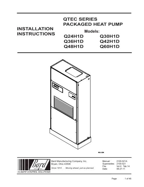
INSTALLATIONINSTRUCTIONSQTEC SERIESPACKAGED HEAT PUMPModels:Q24H1D Q30H1DQ36H1D Q42H1DQ48H1D Q60H1D<strong>Bard</strong> <strong>Manufacturing</strong> <strong>Company</strong>, Inc.Bryan, Ohio 43506Since 1914 . . . Moving ahead, just as planned.Manual: <strong>2100</strong>-<strong>521</strong>ASupersedes: <strong>2100</strong>-<strong>521</strong>File: Vol II Tab 14Date: 06-27-11Manual <strong>2100</strong>-<strong>521</strong>APage 1 of 48
CONTENTSGetting Other Information and PublicationsFor more information, contact these publishers: ...... 3QTEC General InformationQTEC Model Nomenclature ...................................... 4Shipping Damage .................................................... 8Unit Removal From Skid .......................................... 8Handling Unit After Removal From Skid .................. 9General .................................................................... 9Minimum Installation Height ..................................... 9Duct Work .............................................................. 11Filters ..................................................................... 11Fresh Air Intake ...................................................... 12Service Light .......................................................... 12Condensate Drain .................................................. 12Optional Rear Drain Kits ........................................ 12Installation InstructionsMounting the Unit................................................... 19Wiring — Main Power ............................................ 20Wiring — Low Voltage Wiring ................................ 20Low Voltage Connections ...................................... 21General .................................................................. 21FiguresFigure 1 Unit Dimensions ....................................... 7Figure 2 Air Seal Under Unit .................................. 8Figure 3 Removal of Unit From Skid ...................... 8Figure 4 Unit on Appliance Cart ............................. 9Figure 5 Installation With Free Blow Plenum ....... 10Figure 6 Ducted Application ................................. 10Figure 7 Supply Duct Connections ...................... 11Figure 8 Filter Location ........................................ 11Figure 9 Optional Side Drain ................................ 13Figure 10 Standard Rear Drain .............................. 13Figure 11 Rear Drain (Top View) ............................ 13Figure 12AOptional Rear Drain Kit .......................... 14Figure 12BOptional Rear Drain Kit .......................... 15Figure 12COptional Rear Drain Kit .......................... 16Figure 12DOptional Rear Drain Kit .......................... 17Figure 13A Unit Mounting - Method 1 ......................... 18Figure 13B Unit Mounting - Method 2 ......................... 18Figure 14 Removing Locking Screws from Wheels 19Figure 15 Component Location .............................. 20Figure 16 Thermostat Plug Terminals .................... 22Figure 17 Dehum. Wiring w/"X" T-Stat ................... 23Figure 18 Dehum. Wiring w/"X" T-Stat & Demand .... 24Figure 19 Dehum. Wiring w/"X" T-Stat & Vent Opt.... 25Figure 20 Dehum. Wiring w/"E" T-Stat ................... 26Figure 21 Dehum. Wiring w/"G" T-Stat ................... 27Figure 22 Dehum. Wiring w/"I" T-Stat .................... 28Figure 23 Fresh Air Damper Removal .................... 33Figure 24 QERV Removal ...................................... 34Figure 25 CO 2Controller ........................................ 36Figure 26 Dehumidification Mode Circuit ............... 37Figure 27 Cooling Mode Circuit.............................. 38Figure 28 Defrost Control Board ............................ 40Figure 29 Control Disassembly .............................. 44Figure 30 Winding Test .......................................... 44Figure 31 Drip Loop ............................................... 44Figure 32 Fan Blade Setting .................................. 45Manual <strong>2100</strong>-<strong>521</strong>APage 2 of 48Start UpR-410A Refrigerant:General .................................................................. 29Topping Off System Charge ................................... 29Safety Practices ..................................................... 29Description of Standard Equipment ........................... 30Optional CFM ............................................................ 30Important Installer Note ............................................. 30Phase Monitor ........................................................... 30Three Phase Scroll Compressor Start UpInformation ................................................................ 30Service Hints ............................................................. 31Mist Eliminator Service .............................................. 31Vent Options.............................................................. 32Sequence of Operation ............................................. 35Optional Climate Controls Sequenceof Operation ..................................................... 35 & 36Refrigerant Tube Schematic for Reheat Coil ............. 36Pressure Service Ports ............................................. 36Defrost Cycle............................................................. 39TroubleshootingSolid State Heat Pump Control TroubleshootingProcedure.................................................................. 41Checking Temperature Sensor .................................. 42Troubleshooting GE ECM Blower Motors ........ 43-44Fan Blade Setting Dimensions .................................. 45Refrigerant Charge .................................................... 45Pressure Charts ...................................................46-47TablesTable 1 Factory Built-In Electric Heat Table ........... 4Table 2 Electrical Specifications ............................ 5Table 2A Electrical Specifications ............................ 6Table 3 Operating Voltage Range ........................ 20Table 4 Wall Thermostats .................................... 22Table 5 Troubleshooting ...................................... 41Table 6Temperature vs Resistance ofTemperature Sensor................................ 42Table 7 Fan Blade Dimensions ............................ 45Table 8 Superheat at Compressor ....................... 45Table 9 Indoor Blower Performance .................... 45Table 10 Cooling Pressure .................................... 46Table 11 Heating Pressure .................................... 47Table 12 Dehumidification Relay Logic Board ....... 48
GETTING OTHER INFORMATION AND PUBLICATIONSThese publications can help you install the airconditioner or heat pump. You can usually find these atyour local library or purchase them directly from thepublisher. Be sure to consult current edition of eachstandard.National Electrical Code ..................... ANSI/NFPA 70FOR MORE INFORMATION, CONTACT THESEPUBLISHERS:ACCAAir Conditioning Contractors of America1712 New Hampshire AvenueWashington, DC 20009Telephone: (202) 483-9370Fax: (202) 234-4721Standard for the Installation ............. ANSI/NFPA 90Aof Air Conditioning and Ventilating SystemsStandard for Warm Air ......................ANSI/NFPA 90BHeating and Air Conditioning SystemsANSIAmerican National Standards Institute11 West Street, 13th FloorNew York, NY 10036Telephone: (212) 642-4900Fax: (212) 302-1286Load Calculation for ....................... ACCA Manual J orWinter and SummerManual NAir ConditioningLow Pressure, Low Velocity ........ ACCA Manual D orDuct System DesignManual QWinter and SummerAir ConditioningASHRAE American Society of Heating, Refrigeration,and Air Conditioning Engineers, Inc.1791 Tullie Circle, N.E.Atlanta, GA 30329-2305Telephone: (404) 636-8400Fax: (404) 321-5478NFPANational Fire Protection AssociationBatterymarch ParkP.O. Box 9101Quincy, MA 02269-9901Telephone: (800) 344-3555Fax: (617) 984-7057Manual <strong>2100</strong>-<strong>521</strong>APage 3 of 48
QTEC Series General InformationQTEC MODEL NOMENCLATUREQ 36 H 1 D A 10 X X X X X XMODELNUMBERQ - QTECCAPACITY |24 - 2 Ton30 - 2½ Ton36 - 3 Ton42 - 3½ Ton48 - 4 Ton60 - 5 TonHEATPUMPREVISION |SPECIAL UNITS |D - Dehumidificationw/Hot Gas ReheatVOLTS & PHASE |A - 230/208/60/1B - 230/208/60/3C - 460/60/3KW0Z - 0KW05 - 5KW06 - 6KW09 - 9KW10 - 10KW12 - 12KW15 - 15KWFILTER OPTIONSX - 1-Inch Fiberglass(Standard)F - 2-Inch FiberglassP - 2-Inch PleatedVENTILATION OPTIONSX - Barometric Fresh Air Damper (Standard)B - Blank-off PlateR - Energy Recovery Ventilator w/ExhaustP - Commercial Ventilator - Motorized w/ExhaustPower ReturnV - Commercial Ventilator - Motorized w/ExhaustSpring ReturnCOLOR OPTIONSX - Standard BeigeV - Platinum w/SlateFront (Vinyl)4 - Gray paintCOIL OPTIONSX - StandardINTERNAL CONTROLSX - Standard• High Pressure Switch• Low Pressure Switch• Compressor Time DelayE - Low Ambient ControlQ - Outdoor ThermostatR - Low Ambient Control &Outdoor ThermostatCLIMATE CONTROL OPTIONSX - NoneE - Electronic/Prog/Man/Auto/HumidistatG - Electronic/Non Prog/Man/Auto/HumidistatI - Electronic/Prog/Man/Auto/with CO 2ModelsKWQ24H1DAQ30H1DAQ24H1DBTABLE 1FACTORY BUILT-IN ELECTRIC HEAT TABLEQ30H1DBQ24H1DCQ30H1DCQ36H1DAQ42H1DAQ48H1DAQ60H1DAQ36H1DBQ42H1DBQ48H1DBQ60H1DBQ36H1DCQ42H1DCQ48H1DCQ60H1DC240V-1208V-1240V-1208V-1240V-1208V-1480V-3480V-3240V-1208V-1240V-1208V-1480V-3BTUHBTUH5.016,38012,290BTUHBTUHBTUHBTUHBTUHBTUHBTUHBTUHBTUHBTUHBTUH6.020,50015,36020,50015,36020,50020,50020,50015,36020,5009.030,70023,00030,70023,00030,70030,70030,70023,00030,70010.032,67024,57032,67024,57012.041,00030,70041,00015.049,15036,86049,15036,86049,150Manual <strong>2100</strong>-<strong>521</strong>APage 4 of 48
TABLE 2ELECTRICAL SPECIFICATIONSModelQ24H1DA0ZA05A10Q24H1DB0ZB06B09Q24H1DC0ZC06C09Q30H1DA0ZA05A10Q30H1DB0ZB06B09B12Q30H1DC0ZC06C09C12Q36H1DA0ZA05A104 A15Q36H1DB0ZB06B095 B15Q36H1DC0ZC06C095 C15Rated No. FieldVolts Powerand Phase Circuits230/208-1230/208-3460-3230/208-1230/208-3460-3230/208-1230/208-3460-3111 or 2111111111 or 211111111111 or 21 or 2111111113 MinimumCircuitAmpacity2247721735441019232550751837455512212530315681832543525312212627SingleCircuit1 MaximumExternal Fuseor Ckt. Brkr.30508020354515202535508025404560152525304560909030506060152530302 FieldPowerWire Size108412881412108841088614101010864410866141010102 GroundWire1010812101014121010108101010101410101010108810101010141010103 MinimumCircuitAmpacityCkt.A Ckt.B- -- -22 50--------25----------3133----------------50----------5050--------Dual Circuit1 Maximum2 FieldExternal Fuse Poweror Ckt. Breaker Wire SizeCkt.A Ckt.B Ckt.A Ckt.B- - - -- - - -30 50 10 8--------30----------4545----------------50----------5050----------------10----------88----------------8----------88--------2 GroundWire SizeCkt.A--10--------10----------1010--------Ckt. B--10--------10----------1010--------1 Maximum size of the time delay fuse or HACR type circuit breaker for protection of field wiring conductors.2 Based on 75°C copper wire. All wiring must conform to the National Electrical Code and all local codes.3 These “Minimum Circuit Ampacity” values are to be used for sizing the field power conductors. Refer to the National ElectricCode (latest revision), article 310 for power conductor sizing.CAUTION: When more than one field power conductor circuit is run through one conduit, the conductors must be derated. Payspecial attention to Note 8 of Table 310 regarding Ampacity Adjustment Factors when more than three conductorsare in a raceway.4 Maximum KW that can operate with heat pump on is 10KW. Other 5KW energizes during emergency heating only.5 Maximum KW that can operate with heat pump on is 9KW. Other 6KW energizes during emergency heating only.NOTE:Reference Form 7960-582 for dehumidification model performance information.ELECTRICAL SPECIFICATIONS Continued on Page 6 TABLE 2AManual <strong>2100</strong>-<strong>521</strong>APage 5 of 48
TABLE 2AELECTRICAL SPECIFICATIONS(continued from Page 5)SingleCircuitDual CircuitModel3 Minimum1 Maximum2 FieldRated No. Field 3 Minimum1 Maximum2 Field2 Ground2 GroundCircuit External Fuse PowerVolts Power Circuit External Fuse PowerWire SizeWire Ampacity or Ckt. Breaker Wire Sizeand Phase Circuits Ampacity or Ckt. Brkr. Wire SizeCkt.A Ckt.B Ckt.A Ckt.B Ckt.A Ckt.B Ckt.A Ckt. BQ42H1DA0Z1 34508 10 - - - - - - - -A051 59606 10 - - - - - - - -230/208-1A101 or 2 84904 8 34 50 45 50 8 8 10 104 A151 or 2 84904 8 34 50 45 50 8 8 10 10Q42H1DB0Z1 25358 10 - - - - - - - -B061 43508 10 - - - - - - - -230/208-3B091 52606 10 - - - - - - - -5 B151 53606 10 - - - - - - - -Q42H1DC0Z1 1315 14 14 - - - - - - - -C061 2225 10 10 - - - - - - - -460-3C091 2630 10 10 - - - - - - - -5 C151 2730 10 10 - - - - - - - -Q48H1DA0Z1 38508 10 - - - - - - - -A051 or 2 63706 8 38 25 50 25 8 10 10 10230/208-1A101 or 2 88903 8 38 50 50 50 8 8 10 104 A151 or 2 88903 8 38 50 50 50 8 8 10 10Q48H1DB0Z1 29408 10 - - - - - - - -B061 47508 10 - - - - - - - -230/208-3B091 56606 10 - - - - - - - -5 B151 56606 10 - - - - - - - -Q48H1DC0Z1 1520 12 12 - - - - - - - -C061 2425 10 10 - - - - - - - -460-3C091 2830 10 10 - - - - - - - -5 C151 2830 10 10 - - - - - - - -Q60H1DA0Z1 45608 10- - - - - - - -A051 or 2 70904 8 45 25 60 25 8 10 10 10230/208-1A101 or 2 95100 3 8 45 50 60 50 8 8 10 105 A151 or 2 95100 3 8 45 50 60 50 8 8 10 10Q60H1DB0Z1 31458 10- - - - - - - -B095 B15230/208-31158586060661010----------------Q60H1DC0Z1 17251010- - - - - - - -C095 C15460-31131313535881010----------------1 Maximum size of the time delay fuse or HACR type circuit breaker for protection of field wiring conductors.2 Based on 75°C copper wire. All wiring must conform to the National Electrical Code and all local codes.3 These “Minimum Circuit Ampacity” values are to be used for sizing the field power conductors. Refer to the National ElectricCode (latest revision), article 310 for power conductor sizing.CAUTION: When more than one field power conductor circuit is run through one conduit, the conductors must be derated. Payspecial attention to Note 8 of Table 310 regarding Ampacity Adjustment Factors when more than three conductorsare in a raceway.4 Maximum KW that can operate with heat pump on is 10KW. Other 5KW energizes during emergency heating only.5 Maximum KW that can operate with heat pump on is 9KW. Other 6KW energizes during emergency heating only.NOTE:Reference Form 7960-582 for dehumidification model performance information.Manual <strong>2100</strong>-<strong>521</strong>APage 6 of 48
FIGURE 1UNIT DIMENSIONSQ24H1DQ30H1DQ36H1DQ42H1DQ48H1DQ60H1DManual <strong>2100</strong>-<strong>521</strong>APage 7 of 48
SHIPPING DAMAGEUpon receipt of equipment, the carton should bechecked for external signs of shipping damage. Theskid must remain attached to the unit until the unit isready for installation. If damage is found, the receivingparty must contact the last carrier immediately,preferably in writing, requesting inspection by thecarrier’s agent.FIGURE 2AIR SEAL UNDER QTEC UNITUNIT REMOVAL FROM SKIDWARNINGThis unit is heavy and requires more than oneperson to handle and remove from the skid.Check unit wheels to ensure that wheels arelocked before removing from skid. Extremecaution must be taken to prevent injury topersonnel and damage to the unit.Air SealIt is recommended that the unit not be removed fromthe skid with a forklift since the air seal under the unitcould be damaged. See Figure 2.The shipping brackets on each side of the unit must beremoved and discarded. See Figure 3-A. The return airgrille panel can be removed to provide a place to holdthe unit. The unit can be slid forward on the skid untilFIGURE 3REMOVAL OF UNIT FROM SKIDthe front wheels hang over the edge of the skid. SeeFigure 3-B. The unit can be tipped forward and sliddown the edge of the skid until the front wheels touchthe ground. See Figure 3-C. The wheels will not roll.They are shipped from the factory locked so they willnot roll. The back of the skid will have to be held downto keep it from tipping up. The skid can be slid out fromunder the unit. The unit can then be set upright.HoldSkidDownA Shipping Brackets B Front Wheels Over Edge C Front Wheels On FloorManual <strong>2100</strong>-<strong>521</strong>APage 8 of 48
HANDLING UNIT AFTER REMOVALFROM SKIDWARNINGExercise extreme caution when pushing theunit on the rollers. Handle and push from thelower 1/3 of the unit. Insure that debris is noton the floor where the unit is to be moved onthe rollers. Failure to do so could result in theunit tipping over and causing bodily injury and/or damage to the unit.The unit will have to be turned sideways and removedfrom the skid to fit through a 36" doorway. If the doorheight allows, the unit can be slid sideways through thedoor.If the unit can not be slid through the door, then the unitwill have to be put on a cart and tipped down to rollthrough the door. It is recommended that an appliancecart be used with a strap to hold the unit on the cart.The wheels of the unit must be locked. If the wheelswere allowed to roll, the unit could roll off the cart. Theunit should always be carted from the left side. This isthe side where the compressor is located. See Figure 4.APPLIANCECARTFIGURE 4UNIT ON APPLIANCE CARTQTEC UNIT(Right Side)STRAPThe blade of the appliance cart should be slid under thewheels of the unit. The strap of the appliance cartshould be placed around the unit and strapped tightly.Help will be required to tip the unit back onto the cart.The unit can be leaned far enough back to be rolledthrough the door. Be careful when setting the unit backup to keep from damaging the unit.GENERALThe equipment covered in this manual is to be installedby trained, experienced service and installationtechnicians.A QWS-Series wall sleeve supplied as a separateaccessory must be ordered and installed with QTec unit.The unit is designed for use with or without duct work.For use without duct work, Plenum Box QPB42 isrecommended.These instructions explain the recommended method toinstall the air cooled self-contained unit and theelectrical wiring connections to the unit.These instructions and any instructions packaged withany separate equipment required to make up the entireair conditioning system should be carefully read beforebeginning the installation. Note particularly “StartProcedure” and any tags and/or labels attached to theequipment.While these instructions are intended as a generalrecommended guide, they do not supersede any nationaland/or local codes in any way. Authorities havingjurisdiction should be consulted before the installation ismade. See Page 3 for information on codes andstandards.Size of unit for a proposed installation should be basedon heat loss calculation made according to methods ofAir Conditioning Contractors of America (ACCA). Theair duct should be installed in accordance with theStandards of the National Fire Protection Systems ofOther Than Residence Type, NFPA No. 90A, andResidence Type Warm Air Heating and AirConditioning Systems, NFPA No. 90B. Where localregulations are at a variance with instructions, installershould adhere to local codes.MINIMUM INSTALLATION HEIGHTCOMPRESSORThe minimum installation height of the unit with a FreeBlow Plenum is 8 ft. 6 in. This provides enoughclearance for the plenum to be removed. See Figure 5.The minimum installation height for ducted applicationsis 8 ft. 4½ in. This provides enough clearance to installthe duct work. See Figure 6.Manual <strong>2100</strong>-<strong>521</strong>APage 9 of 48
FIGURE 5INSTALLATION WITH FREE BLOW PLENUMFIGURE 6DUCTED APPLICATIONManual <strong>2100</strong>-<strong>521</strong>APage 10 of 48
DUCT WORKAny heat pump is more critical of proper operatingcharge and an adequate duct system than a straight airconditioning unit. All duct work must be properly sizedfor the design airflow requirement of the equipment.Air Conditioning Contractors of America (ACCA) is anexcellent guide to proper sizing. All duct work orportions thereof not in the conditioned space should beproperly insulated in order to both conserve energy andprevent condensation or moisture damage. When ductruns through unheated spaces, it should be insulatedwith a minimum of one inch of insulation. Useinsulation with a vapor barrier on the outside of theinsulation. Flexible joints should be used to connect theduct work to the equipment in order to keep the noisetransmission to a minimum.The QTEC series heat pump has provision to attach asupply air duct to the top of the unit. Duct connectionsize is 12 inches x 20 inches. The duct work is fieldsupplied and must be attached in a manner to allow forease of removal when it becomes necessary to slide theunit out from the wall for service. See Figure 7 forsuggested attachment method.FIGURE 7SUPPLY DUCT CONNECTIONSFor hot water coil option a QPBHWxx-F for free blowor QPBHWxx-D for ducted airflow is used.When used with a ducted supply, a QCX CabinetExtension can be used to conceal the duct work abovethe unit to the ceiling. This extends 20" above the unitfor a total height above the floor of 10'-7/8". The unit isequipped with a variable speed indoor blower motorwhich increases in speed with an increase in duct staticpressure. The unit will therefore deliver proper ratedairflow up to the maximum ESP shown in Table 9.However, for quiet operation of the air system, the ductstatic should be kept as low as practical, within theguidelines of good duct design.FILTERSTwo 1-inch throw away filters [(1) 16x16 and (1)16x20] are supplied with each unit. The filters slide intofilter brackets. Refer to Figure 8.The filters are serviced from the inside of the buildingby opening the hinged door. This door is attached by1/4 turn fasteners and one locking latch.The internal filter brackets are adjustable toaccommodate 2-inch filters. The tabs for the 1-inchfilters must be bent down to allow the 2-inch filters toslide in place.SUPPLY DUCTTO BE FIELDSUPPLIEDFIGURE 8FILTER LOCATIONATTACHMENTSCREWS TOBE FIELDSUPPLIEDFILTERSROOM SIDE OFQTEC UNITDUCT FLANGEPROVIDED WITHUNITNOTE: Unit cabinet, supply air duct and free blowplenum are approved for “0” clearance tocombustible material.The QTEC series heat pumps are designed for use withfree return (non-ducted) and either free blow with theuse of QPB Plenum Box or a duct supply air system.The QPB and QPBHW Plenum Box mounts on top ofthe unit and has both vertically and horizontallyadjustable louvers on the front discharge grille.RETURN AIRGRILLEManual <strong>2100</strong>-<strong>521</strong>APage 11 of 48
FRESH AIR INTAKEThis unit is equipped with a fresh air damper assembly.The damper blade is locked in the closed position whenthe unit is shipped from the factory. To allow thedamper to operate, remove the two plastic locking pins,one on each end of the blade. This will allow formaximum fresh airflow. The damper blade will nowopen when the indoor blower is operating. If less thanmaximum fresh airflow is required, reinsert the plasticpins to limit damper blade opening to desired level.Two extra pins are provided (taped to the inside of theassembly) which may be used to hold the blade in someposition other than minimum or maximum position.This fresh air assembly is located in the rear of the unitand to gain access to make these adjustments removethe air filter service door.All capacity, efficiency and cost of operationinformation as required for Department of Energy“Energyguide” Fact Sheets are based upon the fresh airblank-off plate in place and is recommended formaximum energy efficiency.The blank-off plate is available upon request from thefactory and is installed in place of the fresh air dampershipped with each unit.For details on energy recovery ventilation see Page 31for details.SERVICE LIGHTThe unit is equipped with a service light which signalsthe user that service is required. The light is located inthe upper control panel and is visible only when thehinged service/filter access door is open.The Service Unit light indicates that the unit has beenshut off by a high or low pressure device. This indicatesthat the unit needs to be serviced. See Page 29 fordetails.CONDENSATE DRAINThere are two drain connections on the unit. The reardrain is the primary drain, and is located on the rightlower rear panel of the unit. The optional side drain islocated on the bottom right side of the unit. The sidedrain is shipped with a plug installed.The side drain requires a water trap for proper drainage.See Figure 9. The drain can be routed through the flooror through the wall. If the drain is to be routed throughan unconditioned space, it must be protected fromfreezing. The drain line must be able to be removedfrom the unit if it is necessary to remove the unit from thewall. When the side drain is used, the plug must beremoved and installed in the rear drain outlet.The rear drain can be used with wall thickness of up to10 inches where a water trap can be installed betweenthe unit and the interior wall. See Figure 10. The trapcannot extend beyond the edge of the unit or it willinterfere with the wall mounting bracket. The drain canbe routed through the floor or through the wall. If thedrain is routed through the wall, the drain line must bepositioned such that it will not interfere with the sleeveflange or the grille. See Figure 11. If the drain is to berouted through an unconditioned space, it must beprotected from freezing.OPTIONAL REAR DRAIN KITSOptional Rear Drain Kit, <strong>Bard</strong> Model QCDS48A, isalso available for these products. The optional reardrain kit offers multiple benefits that include thefollowing:• Allows unit to be rolled away from the sleevewithout having to disconnect any hard plumbingconnections.• Allows indoor coil condensate to be easilyconnected to Rear Drain Box while bypassing theoutdoor coil drain pan. This aids in minimizing thepotential for biological growth to occur byminimizing the standing water and exposing it towarm temperatures.See Figures 12A, 12B, 12C and 12D.The drain box permanently mounts onto the wall sleeveand is then either piped directly outdoors, or can bepiped vertically. The Q/Tec unit is then equipped withfittings on the rear of the unit that slide into the drainbox as it is wheeled towards the wall sleeve.NOTE: On models equipped with a refrigerantsubcooler in the lower drain pan may experience a 2-3% decrease in cooling performance and efficiencywhen the indoor condensate is routed around theoutdoor coil drain pan/subcooler assembly. Unit ratedperformance and efficiency are with the indoorcondensate routed to the outdoor coil pan.There is also a heated version of the rear drain boxavailable (Model #QCDS48H) for installation innorthern climates where freezing may occur.Manual <strong>2100</strong>-<strong>521</strong>APage 12 of 48
FIGURE 9OPTIONAL SIDE DRAIN (SIDE VIEW)INSTALLATIONFIGURE 10STANDARD REAR DRAINQTEC UNITFIGURE 11REAR DRAIN (TOP VIEW)DRAIN LINEWALL (MAXIMUM10" FOR REARDRAIN)SLEEVECOUPLINGS NOTSHOWN BUTRECOMMENDEDFOR EASE OFREMOVABILITYFOR SERVICE.WATERTRAPWALLBRACKETUNITManual <strong>2100</strong>-<strong>521</strong>APage 13 of 48
FIGURE 12AOVERFLOW TUBECAULK AROUND TUBEWALL SLEEVEDRAIN BOXMIS-2469Manual <strong>2100</strong>-<strong>521</strong>APage 14 of 48
FIGURE 12BPLUG INSTALLED INSIDE Q/Tec DRAINREAR DRAIN CONNECTION INQ/Tec PRODUCT3/4" PLASTIC PIPE NIPPLESUPPLIED WITH DRAIN BOX KIT(APPLY TEFLON TAPE TOTHREADS)IMPORTANT !1/2" SLIP X 1/2" SLIP X 3/4" NPTTEE SUPPLIED WITH DRAIN BOX KIT(TIGHTEN THREADS SO TEE ISHORIZONTAL TO FLOOR)MIS-2470Manual <strong>2100</strong>-<strong>521</strong>APage 15 of 48
FIGURE 12CREMOVE KNOCK-OUT FORINDOOR DRAIN HOSE CONNECTOR(If Used)MIS-2471Manual <strong>2100</strong>-<strong>521</strong>APage 16 of 48
FIGURE 12DDRAIN HOSE FROM INDOORDRAIN PAN.MOVE HOSE FROM ATTACHMENT INLOWER DRAIN PAN AND SLIDE ONTODRAIN BOX BARB FITTING, SECURINGWITH SUPPLIED CLAMP IF OUTDOORPAN IS BYPASSED. ( WILL REDUCE RISKOF ALGAE GROWTH IN THE OUTDOORPAN BUT AT A SLIGHT COOLINGPERFORMANCE REDUCTION OF 2-3% )MIS-2472Manual <strong>2100</strong>-<strong>521</strong>APage 17 of 48
FIGURE 13AUNIT MOUNTING - Method 1SIDE TRIM(2 PCS.)ENLARGED VIEW OF MOUNTINGBRACKET SHOWING SLEEVE TOCABINET ATTACHMENTSIDE TRIM(2 PCS.)MOUNTING BRACKETMOUNTINGBRACKET#8 SCREWPROVIDED(LIGHT COLOR)WALLSLEEVEBOTTOMTRIM PIECEBOTTOM TRIMEXTENSIONCABINETSIDE PANEL#10 HEXHEAD SCREWPROVIDEDFIGURE 13BUNIT MOUNTING - Method 2Return GrilleSleeveStudWasherNutCondenserDoor (Removed)Lower Control PanelMIS-2689Manual <strong>2100</strong>-<strong>521</strong>APage 18 of 48
INSTALLATION INSTRUCTIONSMOUNTING THE UNITWhen installing a QTEC unit near an interior wall on theleft side, a minimum of 8 inches is required; 12 inches ispreferred.When installing a QTEC unit near an interior wall on theright side, a minimum of 18 inches is required asadditional space is required to connect the side drain. Ifthe rear condensate drain kit QCDS48 is used theminimum can be reduced to 8 inches.This clearance is required to allow for the attachment ofthe unit to the sleeve and side trim pieces to the wall.This unit is to be secured to the wall sleeve withmounting brackets provided. The unit itself, the supplyduct and the free blow plenum are suitable of “0”clearance to combustible material.Following are the steps for mounting the QTEC. Forreference see Figure 13A for external mounting bracketor 13B for internal bolt secured bracket (recommended).1. Attach mounting brackets to the wall sleeve withscrews provided. Either use external mountingbracket (Fig. 13A) or internal bolt bracket (Fig. 13B).2. Position the unit in front of the sleeve with thecondenser section toward the sleeve.3. Remove the locking screws from the wheels.Refer to Figure 14.4. Roll the unit into the sleeve. Make sure to checkboth sides of the unit as it is being rolled to keepit centered in the sleeve. Also check thealignment to the mounting brackets. This unitmust be level from side to side. If adjustmentsare necessary, shim up under the rollers withsheets of steel or any substance that is notaffected by moisture.5. Make sure the gasket on the rear of the unit istouching the sleeve across the top and down bothsides. This is a rain water seal.6. Secure the mounting brackets to the unit withscrews provided, #10 hex head sheet metalscrews (Figure 13A) or use nut and washer tosecure sleeve (Figure 13B).7. Bottom trim extensions are provided for use whenwall is less than 14 inches but greater than 10.5inches. Secure to wall with screws (not provided).8. Attach the bottom trim piece to the unit with thescrews provided (dark colored).9. Position side trim pieces to wall and attach withfield supplied screws. There are two long piecesand two short pieces supplied. The long piecesare to enclose the gap behind the unit. The shortpieces are to fill the gap behind the cabinetextension or the free blow plenum box. Theymay be cut to suit your ceiling height or overlapthe unit side trim. There is sufficient length totrim up to a 10'2" ceiling.NOTE: If the exterior wall thickness is between 5inches to 10.5 inches, a side trim extensionpiece kit, model QSTX42, is available.FIGURE 14REMOVING LOCKING SCREWS FROM WHEELSREMOVE SCREWS FROMWHEELS BEFORE ROLLINGINTO PLACEManual <strong>2100</strong>-<strong>521</strong>APage 19 of 48
WIRING – MAIN POWERRefer to the unit rating plate and/or Table 2/2A for wiresizing information and maximum fuse or “HACR Type”circuit breaker size. Each unit is marked with a“Minimum Circuit Ampacity”. This means that thefield wiring used must be sized to carry that amount ofcurrent. Depending on the installed KW of electricheat, there may be two field power circuits required. Ifthis is the case, the unit serial plate will so indicate. Allmodels are suitable only for connection with copperwire. Each unit and/or wiring diagram will be marked“Use Copper Conductors Only”. These instructionsMUST BE adhered to. Refer to the National ElectricalCode (NEC) for complete current carrying capacity dataon the various insulation grades of wiring material. Allwiring must conform to NEC and all local codes.The electrical data lists fuse and wire sizes (75°Ccopper) for all models, including the most commonlyused heater sizes. Also shown are the number of fieldpower circuits required for the various models withheaters.The unit rating plate lists a “Maximum Time DelayRelay Fuse” or “HACR Type” circuit breaker that is tobe used with the equipment. The correct size must beused for proper circuit protection, and also to assure thatthere will be no nuisance tripping due to the momentaryhigh starting current of the compressor motor.ELECTRICHEATERSTHERMOSTAT& HUMIDISTATCONTROLSDEHUMIDIFICATIONCONTROLFIGURE 15COMPONENT LOCATIONSIDE FIELD WIREENTRANCEREMOTETHERMOSTATTERMINALBLOCKINDOORBLOWERCIRCUIT BREAKERPANEL &CONTROLSLOWERCONTROLPANELThe disconnect access door on this unit may be lockedto prevent unauthorized access to the disconnect.See Start Up section for information on three phasescroll compressor start-ups.The field wiring connections are located behind the topand hinged panel in the circuit breaker panel. SeeFigure 15.WIRING – LOW VOLTAGE WIRING230/208V, 1 PHASE AND 3 PHASE EQUIPMENTDUAL PRIMARY VOLTAGE TRANSFORMERS.All Equipment leaves the factory wired on 240V tap.For 208V operation, reconnect from 240V to 208V tap.The acceptable operating voltage range for the 240 and208V taps are as noted in Table 3.TABLE 3OPERATING VOLTAGE RANGETAPRANGE240V253 – 216208V220 – 187NOTE: The voltage should be measured at the fieldpower connection point in the unit and while theunit is operating at full load (maximumamperage operating condition).The standard Climate Control Option X is a remotethermostat connection terminal block. See Figure 17 forwiring diagram. Compatible thermostats are listed inTable 4.The Climate Control Option E is an electronic,programmable thermostat and a humidistat. The subbase of the thermostat and the humidistat are factorywired to the front panel of the unit. See Figure 19 forwiring diagram. Compatible for use with EnergyRecovery Ventilator or Ventilator.The Climate Control Option G is an electronic,non-programmable thermostat and humidistat. Thesubbase of the thermostat is factory wired to the frontpanel of the unit. This option is compatible for use withthe optional CS2000A* Energy Control Monitor and aterminal block is provided for connection to theCS2000A*. See Figure 20 for wiring diagram.Compatible for use with Energy Recovery Ventilator orVentilator.The Climate Control Option I is an electronic,programmable thermostat, humidistat and a CO 2controller. The subbase of the thermostat and CO 2controller are factory wired to the front panel of the unit.See Figure 21 for wiring diagram.NOTE: On options X and G the CS2000A* (or otherfield provided means to control ventilation) mustbe used if any of the mechanical (motorized)ventilation options are installed.Manual <strong>2100</strong>-<strong>521</strong>APage 20 of 48
LOW VOLTAGE CONNECTIONSThese units use a grounded 24 volt AC low voltagecircuit.The “R” terminal is the hot terminal and the “C”terminal is grounded.“G” terminal or pin 6 of P4 is the fan input.“Y” terminal or pin 7 of P4 is the compressor input.“B” terminal or pin 8 of P4 is the reversing valve input.The reversing valve must be energized for heatingmode.“R” terminal or pin 10 of P4 is 24 VAC hot.“C” terminal or pin 11 of P4 is 24 VAC grounded.“L” terminal or pin 12 of P4 is compressor lockoutoutput. This terminal is activated on a high or lowpressure trip by the electronic heat pump control. Thisis a 24 VAC output.“W2” terminal or pin 9 of P4 is second stage heat (ifequipped). If the unit is equipped with an optional hotwater coil plenum box the water valve will be connectedto this terminal.“O1” terminal of pin 5 of P4 is the ventilation input.This terminal energizes any factory installedventilation option.“E” terminal or pin 3 of P4 is the emergency heat input.This terminal energizes the emergency heat relay.NOTE: For total and proper control using DDC, a totalof 7 controlled outputs are required (6 if noventilation system is installed). For propersystem operation under Emergency Heatconditions where the compressor needs to bedeactivated, the B-W2-E outputs need to beenergized. Removing the Y (compressor) signalalone turns the compressor off, but does notactivate the additional circuitry embedded inthe heat pump for proper and completeoperation.“5” terminal or pin 2 of P4 is the 24 dehumidificationcircuit.“4” terminal of pin 4 or P4 is the dehumidificationcircuit. A contact must connect terminals 4 and 5.“6” terminal of pin 1 of P4 is VAC grounded to thehumidistat, if needed.LOW VOLTAGE CONNECTIONSFORDDC CONTROLFan OnlyCooling ModeHeat PumpHeatingEnergize GEnergize Y, GEnergize Y, G, B2nd Stage Heating Energize G, W2, Y, B(if employed)VentilationEnergize G, O1Dehumidification Connect 4 & 5Emergency Heat Energize B, W2, E, GGENERALThis unit is equipped with a variable speed ECM motor.The motor is designed to maintain rated airflow up tothe maximum static allowed. It is important that theblower motor plugs are not plugged in or unpluggedwhile the power is on. Failure to remove power priorto unplugging or plugging in the motor could result inmotor failure.CAUTIONDo not plug in or unplug blower motorconnectors while the power is on. Failure to doso may result in motor failure.Manual <strong>2100</strong>-<strong>521</strong>APage 21 of 48
Thermostat8403-056(C7232A1008)8403-058(TH5220D1151)8403-060(1120-445)TABLE 4WALL THERMOSTATSPredominant FeaturesCarbon Dioxide Sensor with LCD forSensor Readings2 stage Cool; 2 stage HeatElectronic Non-ProgrammableHP or ConventionalAuto or Manual changeover3 stage Cool; 3 stage HeatProgrammable/Non-Programmable ElectronicHP or ConventionalAuto or Manual changeoverFIGURE 16MIS-1285Manual <strong>2100</strong>-<strong>521</strong>APage 22 of 48
FIGURE 17Dehumidification Wiring DiagramWith "X" Thermostat OptionH200Humidistat3465EGYO/BAUXRCLRc18403-058TH5220D1151ThermostatW1/EED/YO4AO1GGY1YY1O/B BW1W2W2RRCCL8403-060ThermostatL65Low VoltageTerm. BlockBlack/WhiteRed/WhiteRed/YellowPurple/WhiteBrown/WhiteOrangeYellowBlueBrownRed/WhiteBlack/WhitePlug #4123458679101112Black/WhiteRed/WhiteOrangeYellowBlueBrownRedPurple/WhiteBrown/WhiteBlack/WhiteRed/WhiteFreezeProtect Tstat<strong>Bard</strong> Part #8408-038Relay Logic BoardLE1G1RVWA1W2GDLE1BKTWVYOA2RATYBRC1FACTORY INSTALLED JUMPERPinkReturn AirThermostatRed/WhiteBlack/WhitePlug #2BlackRed/YellowPurple/WhiteBrown/WhiteOrangeYellowBlueBrownRed/White123456789101112234102-063 AManual <strong>2100</strong>-<strong>521</strong>APage 23 of 48
FIGURE 18OptionalCO2 Controller#C7232A1008<strong>Bard</strong> Part #8403-05624VACAnalogOutRedBlackYellowBrownOrangeDehumidification Wiring DiagramWith "X" Thermostat OptionAnd Demand VentilationGreenH200Humidistat63 54EGYO/BAUXRCLRc18403-058TH5220D1151ThermostatW1/ED/YO8403-060Thermostat65E4AGY1Y1O/B BW1W2W2RRCCLO1GYLLow VoltageTerm. BlockBlack/WhiteRed/WhiteRed/YellowPurple/WhiteBrown/WhiteOrangeYellowBlueBrownRed/WhiteBlack/WhitePlug #4123458679101112Black/WhiteRed/WhiteOrangeYellowBlueBrownRedPurple/WhiteBrown/WhiteBlack/WhiteRed/WhiteFreezeProtect Tstat<strong>Bard</strong> Part #8408-038Relay Logic BoardLE1G1RVWA1W2GDLE1BKTWVYOA2RATYBRC1FACTORY INSTALLED JUMPERPinkReturn AirThermostatRed/WhiteBlack/WhitePlug #2BlackRed/YellowPurple/WhiteBrown/WhiteOrangeYellowBlueBrownRed/White12345678910111232MIS-2690 AManual <strong>2100</strong>-<strong>521</strong>APage 24 of 48
CO 2 ControllerPart #8403-05624 VACRedBlackAnalogOutYellowBrownOrangeGreenNC C NO C NCVENT HVAC FANAREA OCCUP.NO C NCREM- +FIGURE 19QH Dehumidification Wiring DiagramWith "X" Thermostat Option, CO 2 Controller,CS2000A2 and WERV Ventilation OptionRC65W2BW1O1GInternalFactoryJumpersFactoryJumpersYY14ELUnit Low VoltageTerminal BlockPWRPWR- +- +PRECOND DOORC NCNO C NCHVACMAN.OVERIDE(24 HRS)CS2000A2Energy Monitor32Option1W1/ED/YOAGY1BW2RCLThermostat*Part #8403-060Red/WhiteBlack/WhiteBrown/WhiteRed/WhiteBlack/WhiteBrown/WhiteDouble Pole Relaywith 24V Coil(Field Installed)Plug #3WERVVentilation*Note: Thermostat must be configured for: Heat Pump,No Economizer, Full Time Dehumidification,CS2000A2, Non-ProgrammableMIS-2692Manual <strong>2100</strong>-<strong>521</strong>APage 25 of 48
FIGURE 20Dehumidification Wiring DiagramWith "E" Thermostat OptionPlug #48403-060ThermostatW1/ERed/YellowD/YO Purple/WhiteABrown/WhiteGOrangeY1Yellow1234567Black/WhiteRed/WhiteOrangeYellowRedPurple/WhiteBrown/WhiteFreezeProtect Tstat<strong>Bard</strong> Part #8408-038Relay Logic BoardLE1G1RVWLE1BKTWVA1Blue8BBlueW2YOA2W2BrownRCLRed/WhiteBlack/White9101112BrownRed/WhiteGDRATYBRPinkReturn AirThermostatRed/WhiteBlack/WhiteCBlack/White2Plug #2BlackRed/YellowPurple/WhiteBrown/WhiteOrangeYellowBlueBrownRed/White12345678910111234102-064Manual <strong>2100</strong>-<strong>521</strong>APage 26 of 48
8403-060ThermostatW1/ED/YOGY1O/BW2RLCRed/WhiteFIGURE 21Dehumidification Wiring DiagramWith "G" Thermostat OptionPlug #4Red/YellowPurple/WhiteBrown/WhiteOrangeYellow1234567Black/WhiteRed/WhiteOrangeYellowRedPurple/WhiteBrown/WhiteFreezeProtect Tstat<strong>Bard</strong> Part #8408-038Relay Logic BoardLE1G1RVWLE1BKTWVBlueBrownRed/WhiteRed/WhiteBlack/White89101112BlueBrownA1W2GDRed/WhiteYOA2RATYBRO1 Y Y1 CTerminalBlock #1Black/WhiteCBlack/WhiteRemove jumper when CS2000A Energy Monitor is installed.PinkReturn AirThermostatRed/WhiteBlack/White2Plug #2BlackRed/YellowPurple/WhiteBrown/WhiteOrangeYellowBlueBrownRed/White12345691011781234102-065Manual <strong>2100</strong>-<strong>521</strong>APage 27 of 48
24 VACBlackYellowBrown8403-060ThermostatW1/ED/YOAGY1BW2RCLDehumidification Wiring DiagramWith "I" Thermostat OptionRed/YellowPurple/WhiteOrangeYellowPlug #41234567Black/WhiteRed/WhiteOrangeYellowRedPurple/WhiteBrown/WhiteFreezeProtect Tstat<strong>Bard</strong> Part #8408-038Relay Logic BoardLE1G1RVWLE1BKTWVBlue8BlueA1 YOW2 A2Brown9 BrownG RATRed/White10D YBlack/White11B12Red/WhiteRBlack/WhiteCPinkReturn AirThermostatRed/WhiteBlack/White2Plug #2BlackRed/YellowPurple/WhiteBrown/WhiteOrangeYellowBlueBrown10Red/White11121234567893Brown/WhiteBlack/WhiteRed/WhiteCO Controller<strong>Bard</strong> Part #8403-056RedAnalogOutOrangeGreenFIGURE 224102-066Manual <strong>2100</strong>-<strong>521</strong>APage 28 of 48
START UPTHESE UNITS REQUIRE R-410AREFRIGERANT AND POLYOLESTER OIL.GENERAL:1. Use separate service equipment to avoid crosscontamination of oil and refrigerants.2. Use recovery equipment rated for R-410Arefrigerant.3. Use manifold gauges rated for R-410A (800 psi/250psi low).4. R-410A is a binary blend of HFC-32 and HFC-125.5. R-410A is nearly azeotropic - similar to R-22 andR-12. Although nearly azeotropic, charge withliquid refrigerant.6. R-410A operates at 40-70% higher pressure thanR-22, and systems designed for R-22 cannotwithstand this higher pressure.7. R-410A has an ozone depletion potential of zero,but must be reclaimed due to its global warmingpotential.8. R-410A compressors use Polyol Ester oil.9. Polyol Ester oil is hygroscopic; it will rapidly absorbmoisture and strongly hold this moisture in the oil.10. A liquid line dryer must be used - even a deepvacuum will not separate moisture from the oil.11. Limit atmospheric exposure to 15 minutes.12. If compressor removal is necessary, always plugcompressor immediately after removal. Purge withsmall amount of nitrogen when inserting plugs.TOPPING OFF SYSTEM CHARGEIf a leak has occurred in the system, <strong>Bard</strong> <strong>Manufacturing</strong>recommends reclaiming, evacuating (see criteria above),and charging to the nameplate charge. If done correctly,topping off the system charge can be done withoutproblems.With R-410A, there are no significant changes in therefrigerant composition during multiple leaks andrecharges. R-410A refrigerant is close to being anazeotropic blend (it behaves like a pure compound orsingle component refrigerant). The remainingrefrigerant charge, in the system, may be used afterleaks have occurred and then “top-off” the charge byutilizing the charging charts on the inner control panelcover as a guideline.REMEMBER: When adding R-410A refrigerant, itmust come out of the charging cylinder/tank as a liquidto avoid any fractionation, and to insure optimal systemperformance. Refer to instructions for the cylinder thatis being utilized for proper method of liquid extraction.WARNINGFailure to conform to these practicescould lead to damage, injury or death.SAFETY PRACTICES:1. Never mix R-410A with other refrigerants.2. Use gloves and safety glasses. Polyol Ester oils canbe irritating to the skin, and liquid refrigerant willfreeze the skin.3. Never use air and R-410A to leak check; themixture may become flammable.4. Do not inhale R-410A – the vapor attacks thenervous system, creating dizziness, loss ofcoordination and slurred speech. Cardiacirregularities, unconsciousness and ultimate deathcan result from breathing this concentration.5. Do not burn R-410A. This decompositionproduces hazardous vapors. Evacuate the area ifexposed.6. Use only cylinders rated DOT4BA/4BW 400.7. Never fill cylinders over 80% of total capacity.8. Store cylinders in a cool area, out of directsunlight.9. Never heat cylinders above 125°F.10. Never trap liquid R-410A in manifold sets, gaugelines or cylinders. R-410A expands significantlyat warmer temperatures. Once a cylinder or line isfull of liquid, any further rise in temperature willcause it to burst.Manual <strong>2100</strong>-<strong>521</strong>APage 29 of 48
START UPDESCRIPTION OF STANDARDEQUIPMENTSolid State Electronic Heat Pump ControlProvides efficient 30-minute defrost cycle. A thermistorsensor and speed up terminal for service along with a10- minute defrost override are standard on theelectronic heat pump control.High / Low Pressure SwitchProvides refrigerant circuit high pressure and loss ofcharge protection. Includes lockout circuit that isresettable from room thermostat.Five Minute Compressor Time DelayProvides short cycle protection for the compressorwhich extends compressor life. Built into the electronicheat pump control as standard.Service LightOne service light indicates when service is required.• Check System – detects high or low pressureswitch operation for compressor protection.OPTIONAL CFM (Q36H1D, Q42H1D,Q48H1D AND Q60H1D ONLY)These units are shipped from the factory set to operate atthe optional CFM level shown in Table 9. This provideslower operating sound levels for non-ducted, freedischarge applications. This CFM level will reduce thesystem capacity performance by approximately 2% atthe same energy efficiency.Rated CFM is required for ducted applications formaximum performance rating. To obtain full CFM onthese models, connect jumper wire as follows:1. Disconnect all power to the unit. Failure to do somay result in damage to the motor.2. Open return air access panel.3. Open inner control panel cover.4. Locate low voltage terminal strip. There is a pinkjumper wire with both ends attached to terminalmarked “G2”. Move one end of the jumper toterminal “Y”5. Reverse steps to reassemble.IMPORTANT INSTALLER NOTEFor improved start-up performance, wash the indoor coilwith a dishwasher detergent.PHASE MONITORAll units with three phase scroll compressors areequipped with a 3 phase line monitor to preventcompressor damage due to phase reversal.The phase monitor in this unit is equipped with twoLEDs. If the Y signal is present at the phase monitorand phases are correct the green LED will light and thecompressor contactor is allowed to energize.If phases are reversed, the red fault LED will be lit andcompressor operation is inhibited.If a fault condition occurs, reverse two of the supplyleads to the unit. Do not reverse any of the unit factorywires as damage may occur.THREE PHASE SCROLL COMPRESSORSTART UP INFORMATIONScroll compressors, like several other types ofcompressors, will only compress in one rotationaldirection. Direction of rotation is not an issue withsingle phase compressors since they will always startand run in the proper direction.However, three phase compressors will rotate in eitherdirection depending upon phasing of the power. Sincethere is a 50-50 chance of connecting power in such away as to cause rotation in the reverse direction,verification of proper rotation must be made.Verification of proper rotation direction is made byobserving that suction pressure drops and dischargepressure rises when the compressor is energized.Reverse rotation also results in an elevated sound levelover that with correct rotation, as well as, substantiallyreduced current draw compared to tabulated values.Verification of proper rotation must be made at thetime the equipment is put into service. If improperrotation is corrected at this time there will be nonegative impact on the durability of the compressor.However, reverse operation for even one hour mayhave a negative impact on the bearing due to oil pumpout.All three phase scroll compressors used in the QTECseries are wired identically internally. As a result, oncethe correct phasing is determined for a specific systemor installation, connecting properly phased power leadsto the same Fusite terminal should maintain properrotation direction. The direction of rotation of themotor may be changed by reversing any two lineconnections to the unit.Manual <strong>2100</strong>-<strong>521</strong>APage 30 of 48
SERVICE HINTS1. Caution user to maintain clean air filters at alltimes. Also, not to needlessly close off supply airregisters. This may reduce airflow through thesystem, which shortens equipment service life aswell as increasing operating costs and noiselevels.2. Switching to heating cycle at 75°F or higheroutside temperature may cause a nuisance trip ofthe remote reset high pressure switch. Turnthermostat off, then on to reset the high pressureswitch.3. The heat pump wall thermostats perform multiplefunctions. Be sure that all function switches arecorrectly set for the desired operating modebefore trying to diagnose any reported serviceproblems.4. Check all power fuses or circuit breakers to besure they are the correct rating.5. Periodic cleaning of the outdoor coil to permitfull and unrestricted airflow circulation isessential.6. Some service requires the need to remove the unitfrom the wall including replacement of the indoorcoil and/or the outdoor coil. Also servicing theoutdoor fan motor or fan blade will requireremoving the unit from the wall if the unit isinstalled at a height that is not easily accessiblefrom the outside of the building.In order to remove the unit from the wall thefollowing procedure must be used:a. Turn off power to the unit at the remotelocation. Some units may have more than onepower supply.b. Disconnect field wiring at unit terminal blockand remove from unit.c. Disconnect condensate drain.d. Remove the lower skirting around the unit.e. Remove wall mounting brackets from wall oneach side of the unit.f. If unit is attached to duct work, remove uppercabinet extension by removing the top centerscrew only from the cabinet side panel.g. Remove screws that attach the duct work tothe unit flanges.This unit is equipped with four rollersmounted to the base. For ease of pulling unitout from the wall, you may want to removethe bottom service door which requiresremoval of the return air panel, and grip thefront flange of the base pan then pull straightout.7. Annual maintenance is required to make sure thatall of the systems are functioning properly.a. Check to make sure that the drains are notobstructed in any way.b. Remove any debris in the condenser section ofthe unit.c. Inspect and clean mist eliminator as describedbelow.d. Inspect and wash outdoor coil as necessary.MIST ELIMINATOR SERVICEA mist eliminator is supplied with the wall sleeve. Themist eliminator is constructed of an aluminum frameand mesh. The mist eliminator is located in the topsection of the wall sleeve and can be removed from theinside of the building without removing the unit fromthe wall. This requires that the ventilation package mustbe removed.It is recommended that the mist eliminator be inspectedannually and serviced as required. The mist eliminatorcan be inspected from the outside of the building bylooking through the outdoor grille. The mist eliminatorcan be serviced from the outside by using a vacuumcleaner. The outdoor grille must be removed. Use thevacuum to remove dirt and debris from the surface ofthe mist eliminator. If additional cleaning is required,the mist eliminator will have to be removed from thesleeve.The ventilation package will have to be removed to gainaccess to the mist eliminator. If the blank off plateoption is used, it is not necessary to service the misteliminator. The steps necessary to remove each of thevent options are listed below.The mist eliminator can be cleaned by washing withsoap and water. The excess water should be shaken offthe mist eliminator before it is reinstalled.Manual <strong>2100</strong>-<strong>521</strong>APage 31 of 48
VENT OPTIONSBAROMETRIC FRESH AIR DAMPER (Standard)Before starting, make sure the power has been turnedoff. The return air grille panel must be removed. Thefresh air damper assembly can be seen on the back ofthe unit. See Figure 23.1. The fresh air damper is attached to the back of theunit with one screw on either side of theassembly. Both of the screws must be removed.2. Once the mounting screws are removed, tilt theassembly down and lift it out.The mist eliminator can be seen through the opening.The mist eliminator must be raised up and the bottomcan be pulled toward the front of the unit.COMMERCIAL ROOM VENTILATOR (Option)Before starting, make sure the power has been turnedoff. The return air grille panel must be removed. Thecommercial room ventilator (CRV) can be seen after thepanel has been removed. The CRV must be removed togain access to the mist eliminator.1. The two mounting screws in the front of the CRVmust be removed.2. The power connectors for the CRV (located onthe right side of the unit) must be disconnected.Squeeze the tabs on the sides of the connectorand pull straight out. Unplug both of theconnectors.3. Slide the CRV straight out of the unit.The mist eliminator can be seen through the opening inthe back of the unit. The mist eliminator must be raisedup and the bottom can be pulled toward the front of theunit and removed.QTEC R ENERGY RECOVERY VENTILATOR(Option)Before starting, make sure that the power has beenturned off. The return air grille panel must be removed.The energy recovery ventilator (QERV) can be seenafter the panel has been removed. To gain access to themist eliminator, the QERV must be removed. SeeFigure 24.1. The front fill plate of the QERV must beremoved. There is one screw on either side of theplate. Remove these screws and remove theplate.2. On either side of the QERV there are mountingscrews that hold the QERV in place. Removeboth of these screws.3. Underneath the heat recovery cassette there is apower connector for the lower blower assembly.To disconnect this plug, the tabs on both sides ofthe plug must be squeezed to release the plug.While squeezing the tabs, pull the plug out of thesocket.4. The QERV is plugged into the unit in the rightside of the unit. Both of these plugs must bedisconnected to remove the QERV. Squeeze thetabs on the sides of the connector and pullstraight out.5. Slide the QERV assembly straight out of the unit,being careful not to let the cassette slide out ofthe QERV.The mist eliminator can be seen through the opening inthe back of the unit. The mist eliminator must be raisedup and the bottom can be pulled toward the front of theunit and removed.Manual <strong>2100</strong>-<strong>521</strong>APage 32 of 48
FIGURE 23FRESH AIR DAMPER REMOVALMOUNTINGSCREWManual <strong>2100</strong>-<strong>521</strong>APage 33 of 48
FIGURE 24QERV REMOVALPOWERCONNECTORSMOUNTINGSCREWSLOWER BLOWERASSEMBLY POWERCONNECTORFRONT FILLManual <strong>2100</strong>-<strong>521</strong>APage 34 of 48
SEQUENCE OF OPERATIONCooling – Circuit R-Y makes the thermostat pull in thecompressor contactor starting the compressor andoutdoor motor. The G (indoor motor) circuit isautomatically completed on any call for coolingoperation, or can be energized by manual fan switch onsubbase for constant air circulation.Heating – A 24V solenoid coil on the reversing valvecontrols heating cycle operation. Two thermostatoptions, one allowing “Auto” change over from cycle tocycle and the other constantly energizing solenoid coilduring heating season and thus eliminating pressureequalization noise except during defrost, are to be usedon “Auto” option, a circuit is completed for R-W1 andR-Y on each heating “on” cycle, energizing reversingvalve solenoid and pulling in compressor contactorstarting compressor and outdoor motor. R-G also makesstarting indoor blower motor. Heat pump heating cyclenow in operation.The second option has no “Auto” change over position,but instead energizes the reversing valve solenoidconstantly whenever the system switch on subbase isplaced in “Heat” position, the “B” terminal beingconstantly energized from R. A thermostat demand forheat completes R-Y circuit, pulling in compressorcontactor starting compressor and outdoor motor. R-Galso make starting indoor blower motor.Reheat Circuit – There is a small capillary tube insertedbetween the reheat coil return line and suction line thatwill prevent liquid from accumulating in the reheat coilwhen it is inactive. This drain does not affect thenormal operation of the system.There is a check valve located in the reheat coil returnline. It has a soft spring to hold the ball on the seat. Thiswill make the method of checking the ball freedom witha magnet difficult. Refer to Figures 26 and 27 for thelocation of the check valve and drain back capillary.When the system is operating in the dehumidificationmode, the suction pressure will be reduced by 4 to 8psig and the discharge pressure will be reduced by 19 to22 psig.Return Air Thermostat – In dehumidification mode ifthe return air temperature is lower than 65°, the returnair thermostat closes and brings on stage one electricheat to maintain 65°.High / Low Pressure Control provides protection forthe compressor. In the event system pressures go above600 PSI or below 15 PSI in either cooling or heatingmode the compressor will be stopped. This will activatethe red light located in the control panel. The lockoutcircuit will hold compressor off line. When the systemproblem is corrected, the unit operation can be restoredby turning of the main power supply off and then backon, or reset the room thermostat. The low pressurecontrol has a bypass to eliminate nuisance lockout oncold start up.The bypass timer should be set to 120 seconds. This is toassure there is no nuisance tripping of the low-pressurecontrol during startup in heating mode under coldweather conditions.OPTIONAL CLIMATE CONTROLSSEQUENCE OF OPERATIONThe Climate Control Option E is an electronic,programmable thermostat and a humidistat. This unithas a refrigerant reheat circuit that is controlled by a 3way valve.When the humidity is above the setpoint of thehumidistat, the compressor circuit and the 3 way valveare energized and the evaporator airflow is reduced.The 3 way valve directs hot discharge gas into aseparate desuperheating condenser circuit that reheatsthe conditioned air before it is delivered to the room.When the humidistat is satisfied, the system switchesback to normal air conditioning mode.If the thermostat calls for cooling duringdehumidification mode, the call for cooling takesprecedence over the dehumidification and the unit willcool until the thermostat is satisfied. Once the call forcooling is satisfied, the unit may continue todehumidify.If the thermostat calls for heat when the unit is in thedehumidification mode, the electric heaters willenergize and the evaporator airflow will return to theheating airflow. When the thermostat is satisfied, theelectric heaters will turn off and the airflow will bereduced and the system will continue to dehumidifyuntil humidistat is satisfied.If the unit is running in heat pump mode and thehumidistat calls for dehumidification, thedehumidification mode takes precedence over the heatpump heating mode. The unit will not return to theheating mode until 2nd stage heating is called for.The Climate Control Option I is an electronic,programmable thermostat, humidistat and CO 2controller. This unit has a refrigerant reheat circuit thatis controlled by a 3 way valve.When the humidity is above the setpoint of thehumidistat, the compressor circuit and the 3 way valveare energized and the evaporator airflow is reduced.The 3 way valve directs hot discharge gas into aseparate desuperheating condenser circuit that reheatsthe conditioned air before it is delivered to the room.When the humidistat is satisfied, the system switchesback to normal air conditioning mode.If the thermostat calls for cooling duringdehumidification mode, the call for cooling takesprecedence over the dehumidification and the unit willcool until the thermostat is satisfied. Once the call forcooling is satisfied, the unit may continue todehumidify.Manual <strong>2100</strong>-<strong>521</strong>APage 35 of 48
If the thermostat calls for heat when the unit is in thedehumidification mode, the electric heaters willenergize and the evaporator airflow will return to theheating airflow. When the thermostat is satisfied, theelectric heaters will turn off and the airflow will bereduced and the system will continue to dehumidifyuntil humidistat is satisfied.If the unit is running in heat pump mode and thehumidistat calls for dehumidification, thedehumidification mode takes precedence over the heatpump heating mode. The unit will not return to theheating mode until 2nd stage heating is called for.The CO 2controller will energize the vent option and theID blower when the room CO 2levels rise over set level.Default CO 2set point is 1000 ppm. See Figure 25.FIGURE 25CO 2CONTROLLER - FACTORY SET TO 1000 PPM"SW2" SET TO ONSW2SW1OUT ANOFFONOFFON0-100%20-100%VOLTAGECURRENT"AN" SET TO VOLTAGE"SW1" SET TO ON "OUT" SET TO 20-100%MIS-2667The Climate Control Option G has a non-programmableelectronic thermostat, humidistat and is compatible foruse with a CS2000A* Energy Control Monitor. Thisunit has a refrigerant reheat circuit that is controlled bya three-way valve.Unit operation is controlled by the thermostat andhumidistat, and optional CS2000A* Energy MonitorController can be easily integrated by simple connectionto the low voltage terminal block provided. See Figure21.NOTE: The CS2000A* (or other means for ventilationcontrol) must be used if any mechanical(motorized) ventilation options are installed.Dehumidification can be set to be available only whenCS2000A* is active or to be available continuously byswitching a jumper on the relay logic board. See noteson Table 12.When the humidity is above the setpoint of thehumidistat, the compressor circuit and the 3 way valveare energized and the evaporator airflow is reduced.The 3 way valve directs hot discharge gas into aseparate desuperheating condenser circuit that reheatsthe conditioned air before it is delivered to the room. Ifthe return air thermostat sensed a temperature below 65°during dehumidification, the fist stage electric heatersare brought on to raise the return air temperature above65°. When the humidistat is satisfied, the systemswitches back to normal air conditioning mode.If the thermostat calls for cooling duringdehumidification mode, the call for cooling takesprecedence over the dehumidification and the unit willcool until the thermostat is satisfied. Once the call forcooling is satisfied, the unit may continue todehumidify.If the thermostat calls for heat when the unit is in thedehumidification mode, the electric heaters willenergize and the evaporator airflow will return to theheating airflow. When the thermostat is satisfied, theelectric heaters will turn off and the airflow will bereduced and the system will continue to dehumidifyuntil humidistat is satisfied.If the unit is running in heat pump mode and thehumidistat calls for dehumidification, thedehumidification mode takes precedence over the heatpump heating mode. The unit will not return to theheating mode until 2nd stage heating is called for.REFRIGERANT TUBE SCHEMATIC FORREHEAT COILFigure 26 shows the refrigerant gas flow through thereheat coil during the dehumidification mode.When the unit is in standard cooling (Figure 27) orheating mode the reheat coil is inactive.PRESSURE SERVICE PORTSHigh and low pressure service ports are installed on allunits so that the system operating pressures can beobserved. Pressure curves can be found later in themanual covering all models on both cooling and heatingcycles. It is imperative to match the correct pressurecurve to the unit by model number. Upper and lowerservice doors must be attached to obtain proper reading.Manual <strong>2100</strong>-<strong>521</strong>APage 36 of 48
FIGURE 26QTEC DEHUMIDIFICATION MODE CIRCUIT DIAGRAMManual <strong>2100</strong>-<strong>521</strong>APage 37 of 48
Manual <strong>2100</strong>-<strong>521</strong>APage 38 of 48FIGURE 27QTEC COOLING MODE CIRCUIT DIAGRAM
DEFROST CYCLEThe defrost cycle is controlled by temperature and timeon the solid state heat pump control. See Figure 28.When the outdoor temperature is in the lower 40°Ftemperature range or colder, the outdoor coiltemperature is 32°F or below. This coil temperature issensed by the coil temperature sensor mounted near thebottom of the outdoor coil. Once coil temperaturereaches 30°F or below, the coil temperature sensorsends a signal to the control logic of the heat pumpcontrol and the defrost timer will start.After 30 minutes (Default Setting) of run time at 30°For below, the heat pump control will place the system inthe defrost mode.During the defrost mode, the refrigerant cycle switchesback to the cooling cycle, the outdoor motor stops,electric heaters are energized, and hot gas passingthrough the outdoor coil melts any accumulated frost.When the temperature rises to approximately 57°F, thecoil temperature sensor will send a signal to the heatpump control which will return the system to heatingoperations automatically.If some abnormal or temporary condition such as a highwind causes the heat pump to have a prolonged defrostcycle, the heat pump control will restore the system toheating operation automatically after 10 minutes.The heat pump defrost control board has an option of30, 60 or 90-minute setting. All models are shippedfrom the factory on the 30-minute pin. If specialcircumstances require a change to another time, removethe wire from the 30-minute terminal and reconnect tothe desired terminal. The manufacturer’srecommendation is for 30-minute defrost cycles. Referto Figure 28.There is a cycle speed up jumper on the control. Thiscan be used to reduce the time between defrost cycleoperation without waiting for time to elapse.Use a small screwdriver or other metallic object, oranother ¼ inch QC, to short between the SPEEDUPterminals to accelerate the HPC timer and initiatedefrost.Be careful not to touch any other terminals with theinstrument used to short the SPEEDUP terminals. Itmay take up to 10 seconds with the SPEEDUPterminals shorted for the speedup to be completed andthe defrost cycle to start.As soon as the defrost cycle kicks in remove theshorting instrument from the SPEEDUP terminals.Otherwise the timing will remain accelerated and runthrough the 1-minute minimum defrost length sequencein a matter of seconds and will automatically terminatethe defrost sequence.There is an initiate defrost jumper (sen jump) on thecontrol that can be used at any outdoor ambient duringthe heating cycle to simulate a 0° coil temperature.This can be used to check defrost operation of the unitwithout waiting for the outdoor ambient to fall into thedefrost region.By placing a jumper across the SEN JMP terminals (a¼ inch QC terminal works best) the defrost sensormounted on the outdoor coil is shunted out and willactivate the timing circuit. This permits the defrostcycle to be checked out in warmer weather conditionswithout the outdoor temperature having to fall into thedefrost region.In order to terminate the defrost test the SEN JMPjumper must be removed. If left in place too long, thecompressor could stop due to the high pressure controlopening because of high pressure condition created byoperating in the cooling mode with outdoor fan off.Pressure will rise fairly fast as there is likely no actualfrost on the outdoor coil in this artificial test condition.There is also a 5-minute compressor time delay functionbuilt into the HPC. This is to protect the compressor fromshort cycling conditions. The board’s LED will have a fastblink rate when in the compressor time delay. In someinstances, it is helpful to the service technician to overrideor speed up this timing period, and shorting out theSPEEDUP terminals for a few seconds can do this.Low Pressure Switch Bypass Operation - The controlhas a selectable (SW1) low pressure switch bypass setup to ignore the low pressure switch input during thefirst (30, 60, 120 or 180 seconds) of “Y” operation.Factory setting is 120 seconds.After this period expires, the control will then monitorthe low pressure switch input normally to make surethat the switch is closed during “Y” operation.Manual <strong>2100</strong>-<strong>521</strong>APage 39 of 48
FIGURE 28DEFROST CONTROL BOARDLOW PRESSURE BYPASS TIMER SWITCH(FACTORY SETTING 120 SECONDS)SW1OFFONOFFONSW2 TIME (SEC)OFFOFFONON3060120*180OFFONACCUMULATED RUN TIME SELECTOR(FACTORY SETTING 30 MIN.)MIS-2684 AManual <strong>2100</strong>-<strong>521</strong>APage 40 of 48
TROUBLESHOOTINGSOLID STATE HEAT PUMP CONTROLTROUBLESHOOTING PROCEDURE1. NOTE: A thorough understanding of the defrostcycle sequence is essential. Review that sectionearlier in this manual prior to troubleshooting thecontrol. Turn on AC power supply to unit.2. Turn thermostat blower switch to “fan on” – theindoor blower should start. (If it doesn’t,troubleshoot indoor unit and correct problem.)3. Turn thermostat blower to “auto” position. Indoorblower should stop. NOTE: Many models have a1-minute blower time delay on “off” command;wait for this to time-out.4. Set system switch to “heat” or “cool”. Adjustthermostat to call for heat or cool. The indoorblower, compressor and outdoor fan should start.NOTE: If there was no power to 24 volt transformer,the compressor and outdoor fan motor willnot start for 5 minutes. This is because ofthe compressor short cycle protection.CODES FUNCTIONSlow Blink Normal OperationFast Blink Compressor Time Delay1 Blink Low Pressure Switch Failure2 Blink High Pressure Switch Failure3 Blink Defrost Mode ActiveSymptomCompressor willnot start (heatingor cooling)Fan outdoor motordoes not run(cooling or heatingexcept duringdefrost)Reversing valvedoes not energize(heating only)Unit will not gointo defrost(heating only)Unit will not comeout of defrost(heating only)Description,Check & Possible CausesTABLE 5TROUBLESHOOTING1. Check for LED illumination.Yes = go to Step #2; No = go to Step #3Is there an LED illuminated on the board (flashing)?2. Check for error codes.Yes = go to Step #4; No = go to Step #8Is the LED flashing a Code?3. Check for power at board.Yes = go to Step #13; No = go to Step #9Is there 24 volts AC between R and C?4. Check codes.What code is blinking?5. Compressor delay active.Wait for 5 minute delay or jump board's "speed up pins".6 . Low pressure fault.Check wiring circuit and unit pressures.What & How to Check / RepairCode "1", go to Step #6; Code "2", go to Step#7; Fast Blink, go to Step #5Check for proper operation; if still needed, go back to Step #1.7 . High pressure fault.Check wiring circuit and unit pressures.8. Check for Compressor input signal.Is there 24 volts AC between Y and C?Yes = go to Step #10; No = go to Step #119 . No power to board.The unit either does not have unit voltage, the transformer is bad or the unit wiring is incorrect.10. Check for Compressor output signal.Is there 24 volts AC between CC & C?Yes = go to Step #12; No = go to Step #1311.No "Y" compressor input signal.Check thermostat wiring, incorrect phase of unit (see section on Phase Monitor), and finallyunit wiring.12.No "CC" compressor output signal.Check compressor contactor for proper operation and finally check compressor.13.Faulty board.Replace defrost board.H eat pump control defectiveCheck across fan relay on heat pump control. (Com-NC)Replace heat pump control.M otor defectiveCheck for open or shorted motor winding. Replace motor.M otor capacitor defectiveCheck capacitor rating. Check for open or shorted capacitor. Replace capacitor.H eat pump control defectiveCheck for 24V between RV-C and B-C.1. Check control circuit wiring.2. Replace heat pump controlR eversing valve solenoid coil defectiveCheck for open or shorted coil.Replace solenoid coil.Temperaturesensor or heat pump control defective Disconnect temperature sensor from board and jumper across "SPEEDUP" terminals and "SENJMP" terminals. This should cause the unit to go through a defrost cycle within one minute.1. If unit goes through defrost cycle, replace temperature sensor.2. If unit does not go through defrost cycle, replace heat pump control.T emperature sensor or heat pump control defective. Jumper across "SPEEDUP" terminal.This should cause the unit to come out of defrost within one minute.1. If unit comes out of defrost cycle, replace temperature sensor.2. If unit does not come out of defrost cycle, replace heat pump control.Manual <strong>2100</strong>-<strong>521</strong>APage 41 of 48
CHECKING TEMPERATURE SENSOR1. Disconnect temperature sensor from board and fromoutdoor coil.2. Use an ohmmeter and measure the resistance of thesensor. Also use ohmmeter to check for short oropen.3. Check resistance reading to chart of resistance usesensor ambient temperature. (Tolerance of part is ±10%.)4. If sensor resistance reads very low, then sensor isshorted and will not allow proper operation of theheat pump control.5. If sensor is out of tolerance, shorted, open, or readsvery low ohms then it should be replaced.TABLE 6TEMPERATURE (F) VS RESISTANCE (R) OF TEMPERATURE SENSORF R F R F R F R F R-25.01968715.07291035.02998665.01347495.06531-24.01900996.07067036.02915766.01313796.06383-23.01835857.06850737.02835567.01281097.06239-22.01773188.06641838.02757768.01249298.06098-21.01712899.06439939.02682369.01218399.05961-20.016548710.06244940.02608270.011883100.02827-19.015990411.06056541.02538371.011591101.04697-18.015452912.05874542.02469672.011307102.05570-17.014935513.05698543.02403073.011031103.05446-16.014437414.05528444.02338474.010762104.05326-15.013957615.05364045.02275875.010501105.05208-14.013495616.05205146.02215076.010247106.05094-13.013050617.05051447.02156177.010000107.04982-12.012621918.04902848.02098978.09760108.04873-11.012208919.01459049.02043579.08526109.04767-10.011810820.04620050.01989680.09299110.07663-9.011427221.04485551.01937481.09077111.04562-8.011057522.04355452.01886782.08862112.04464-7.010701023.04229553.01837583.08653113.04367-6.010357424.04107754.01798984.08449114.07274-5.010026025.03989855.01743485.08250115.04182-4.09706426.03875756.01698486.08057116.04093-3.09398127.03765257.01654787.07869117.04006-2.09100828.03658358.01612288.07686118.03921-1.08813929.03554859.01571089.07507119.038380.08537130.03454560.01531090.07334120.037571.08269931.03357461.01492191.07165121.036782.08012132.03263462.01454492.07000122.036013.07763233.03172363.01417793.06840123.035264.07523034.03084064.01382094.06683124.03452Manual <strong>2100</strong>-<strong>521</strong>APage 42 of 48
TROUBLESHOOTING GE ECM MOTORSCaution:Disconnect power from unit before removing or replacingconnectors, or servicing motor. To avoid electric shock fromthe motor’s capacitors, disconnect power and wait at least 5minutes before opening motor.Symptom Cause/ProcedureMotor rocks slightly • This is normal start-up for ECMwhen startingMotor won’t start• No movement• Motor rocks,but won’t start• Check blower turns by hand• Check power at motor• Check low voltage (24 Vac R to C) at motor• Check low voltage connections(G, Y, W, R, C) at motor• Check for unseated pins in connectors onmotor harness• Test with a temporary jumper between R - G• Check motor for tight shaft• Perform motor/control replacement check• Perform Moisture Check• Check for loose or compliant motor mount• Make sure blower wheel is tight on shaft• Perform motor/control replacement checkMotor oscillates up • It is normal for motor to oscillate with no load& down while being on shafttested off of blowerMotor starts, butruns erratically• Varies up and downor intermittent• Check line voltage for variation or “sag”• Check low voltage connections(G, Y, W, R, C) at motor, unseated pins inmotor harness connectors• Check “Bk” for erratic CFM command (invariable-speed applications)• Check out system controls, Thermostat• Perform Moisture Check• “Hunts” or “puffs” at • Does removing panel or filter reducehigh CFM (speed) “puffing”?- Reduce restriction- Reduce max airflow• Stays at low CFM • Check low voltage (Thermostat) wires anddespite system call connectionsfor cool or heat CFM • Verify fan is not in delay mode; wait untildelay complete• “R” missing/not connected at motor• Perform motor/control replacement check• Stays at high CFM• “R” missing/not connected at motor• Is fan in delay mode? - wait until delay timecomplete• Perform motor/control replacement check• Blower won’t shut off • Current leakage from controls into G, Y or W?Check for Triac switched thermostat or solidstaterelayExcessive noise• Air noise• Determine if it’s air noise, cabinet, duct ormotor noise; interview customer, if necessary• High static creating high blower speed?- Is airflow set properly?- Does removing filter cause blower to slowdown? Check filter- Use low-pressure drop filter- Check/correct duct restrictionsSymptom• Noisy blower or cabinetCause/Procedure• Check for loose blower housing, panels, etc.• High static creating high blower speed?- Check for air whistling through seams inducts, cabinets or panels- Check for cabinet/duct deformation• “Hunts” or “puffs” at • Does removing panel or filter reducehigh CFM (speed) “puffing”?- Reduce restriction- Reduce max. airflowEvidence of Moisture• Motor failure orCheckmalfunction has occurredand moisture is present• Evidence of moisturepresent inside air mover• Replace motor and Perform Moisture• Perform Moisture CheckDoDon’t• Check out motor, controls, • Automatically assume the motor is bad.wiring and connectionsthoroughly before replacingmotor• Orient connectors down so • Locate connectors above 7 and 4 o’clockwater can’t get in positions- Install “drip loops”• Use authorized motor and • Replace one motor or control model # withmodel #’s for replacement another (unless an authorized replacement)• Keep static pressure to a • Use high pressure drop filters some have ½"minimum: H20 drop!- Recommend high • Use restricted returnsefficiency, low static filters- Recommend keeping filtersclean.- Design ductwork for min.static, max. comfort- Look for and recommendductwork improvement,where necessary• Size the equipment wisely• Check orientation beforeinserting motor connectors• Oversize system, then compensate with lowairflow• Plug in power connector backwards• Force plugsMoisture Check• Connectors are oriented “down” (or as recommended by equipmentmanufacturer)• Arrange harness with “drip loop” under motor• Is condensate drain plugged?• Check for low airflow (too much latent capacity)• Check for undercharged condition• Check and plug leaks in return ducts, cabinetComfort Check• Check proper airflow settings• Low static pressure for lowest noise• Set low continuous-fan CFM• Use humidistat and 2-speed cooling units• Use zoning controls designed for ECM that regulate CFM• Thermostat in bad location?Manual <strong>2100</strong>-<strong>521</strong>APage 43 of 48
TROUBLESHOOTING GE ECM MOTORS CONT’D.Replacing ECM Control ModuleTo replace the control module for the GE variable-speed indoor blowermotor you need to take the following steps:1. You MUST have the correct replacement module. The controls arefactory programmed for specific operating modes. Even though they lookalike, different modules may have completely different functionality.USING THE WRONG CONTROL MODULE VOIDS ALL PRODUCTWARRANTIES AND MAY PRODUCE UNEXPECTED RESULTS.2. Begin by removing AC power from the furnace or air handler beingserviced. DO NOT WORK ON THE MOTOR WITH AC POWERAPPLIED. To avoid electric shock from the motor’s capacitors, disconnectpower and wait at least 5 minutes before opening motor.3. It is usually not necessary to remove the motor from the blowerassembly. However, it is recommended that the whole blower assembly,with the motor, be removed from the furnace/air handler. (Follow themanufacturer’s procedures). Unplug the two cable connectors to the motor.There are latches on each connector. DO NOT PULL ON THE WIRES.The plugs remove easily when properly released.4. Locate the two standard ¼" hex head bolts at the rear of the controlhousing (at the back end of the control opposite the shaft end). Refer toFigure 29. Remove these two bolts from the motor and control assemblywhile holding the motor in a way that will prevent the motor or controlfrom falling when the bolts are removed. If an ECM2.0 control is beingreplaced (recognized by an aluminum casting rather that a deep-drawnblack steel can housing the electronics), remove only the hex-head bolts.DO NOT REMOVE THE TORX-HEAD SCREWS.5. The control module is now free of mechanical attachment to themotor endshield but is still connected by a plug and three wires insidethe control. Carefully rotate the control to gain access to the plug atthe control end of the wires. With thumb and forefinger, reach thelatch holding the plug to the control and release it by squeezing thelatch tab and the opposite side of the connector plug and gently pullingthe plug out of the connector socket in the control. DO NOT PULLON THE WIRES. GRIP THE PLUG ONLY.6. The control module is now completely detached from the motor.Verify with a standard ohmmeter that the resistance from each motorlead (in the motor plug just removed) to the motor shell is >100K ohms.Refer to Figure 30. (Measure to unpainted motor end plate.) If anymotor lead fails this test, do not proceed to install the control module.THE MOTOR IS DEFECTIVE AND MUST BE REPLACED.Installing the new control module will cause it to fail also.7. Verify that the replacement control is correct for yourapplication. Refer to the manufacturer's authorized replacement list.USING THE WRONG CONTROL WILL RESULT INIMPROPER OR NO BLOWER OPERATION. Orient the controlmodule so that the 3-wire motor plug can be inserted into the socket inthe control. Carefully insert the plug and press it into the socket untilit latches. A SLIGHT CLICK WILL BE HEARD WHENPROPERLY INSERTED. Finish installing the replacement controlper one of the three following paragraphs, 8a, 8b or 8c.8a. IF REPLACING AN ECM 2.0 CONTROL (control in castaluminum can with air vents on the back of the can) WITH AN ECM2.3 CONTROL (control containing black potting for water protection inblack deep-drawn steel case with no vents in the bottom of the can),locate the two through-bolts and plastic tab that are packed with thereplacement control. Insert the plastic tab into the slot at the perimeterof the open end of the can so that the pin is located on the inside of theperimeter of the can. Rotate the can so that the tab inserts into the tablocater hole in the endshield of the motor. Using the two through-boltsprovided with the replacement control, reattach the can to the motor.THE TWO THROUGH-BOLTS PROVIDED WITH THEREPLACEMENT ECM 2.3 CONTROL ARE SHORTER THANTHE BOLTS ORIGINALLY REMOVED FROM THE ECM 2.0CONTROL AND MUST BE USED IF SECURE ATTACHMENTOF THE CONTROL TO THE MOTOR IS TO BE ACHIEVED.DO NOT OVERTIGHTEN THE BOLTS.8b. IF REPLACING AN ECM 2.3 CONTROL WITH AN ECM2.3 CONTROL, the plastic tab and shorter through-bolts are notneeded. The control can be oriented in two positions 180° apart.MAKE SURE THE ORIENTATION YOU SELECT FORREPLACING THE CONTROL ASSURES THE CONTROL'SCABLE CONNECTORS WILL BE LOCATED DOWNWARD INTHE APPLICATION SO THAT WATER CANNOT RUN DOWNTHE CABLES AND INTO THE CONTROL. Simply orient thenew control to the motor's endshield, insert bolts, and tighten. DONOT OVERTIGHTEN THE BOLTS.8c. IF REPLACING AN ECM 2.0 CONTROL WITH AN ECM2.0 CONTROL (It is recommended that ECM 2.3 controls be used forall replacements), the new control must be attached to the motor usingthrough bolts identical to those removed with the original control. DONOT OVERTIGHTEN THE BOLTS.9. Reinstall the blower/motor assembly into the HVAC equipment.Follow the manufacturer's suggested procedures.10. Plug the 16-pin control plug into the motor. The plug is keyed.Make sure the connector is properly seated and latched.11. Plug the 5-pin power connector into the motor. Even though theplug is keyed, OBSERVE THE PROPER ORIENTATION. DONOT FORCE THE CONNECTOR. It plugs in very easily whenproperly oriented. REVERSING THIS PLUG WILL CAUSEIMMEDIATE FAILURE OF THE CONTROL MODULE.12. Final installation check. Make sure the motor is installed as follows:a. Unit is as far INTO the blower housing as possible.b. Belly bands are not on the control module or covering vent holes.c. Motor connectors should be oriented between the 4 o’clockand 8 o’clock positions when the blower is positioned in itsfinal location and orientation.d.Add a drip loop to the cables so that water cannot enter themotor by draining down the cables. Refer to Figure 31.The installation is now complete. Reapply the AC power to theHVAC equipment and verify that the new motor control module isworking properly. Follow the manufacturer's procedures fordisposition of the old control module.Only removeFrom MotorHex Head Bolts Push untilLatch SeatsOver RampCircuitBoardECM 2.0Note:Use the shorterbolts andalignment pinsupplied whenreplacing anECM 2.0control.ECM2.3/2.5Figure 29 3Control DisassemblyMotorMotor Connector(3-pin)Control Connector(16-pin)Power Connector(5-pin)Hex-head ScrewsMotor Connector(3-pin)Back ofControlFigure 430Winding TestFigure 31 5Drip LoopMotor OK whenR > 100k ohmConnector OrientationBetween 4 and 8 o'clockDrip LoopManual <strong>2100</strong>-<strong>521</strong>APage 44 of 48
FAN BLADE SETTING DIMENSIONSAny service work requiring removal or adjustment inthe fan and/or motor area will require that thedimensions in Table 7 be checked and blade adjusted inor out of the motor shaft accordingly.FIGURE 32FAN BLADE SETTINGTABLE 7FAN BLADE DIMENSIONSMODELDIMENSION(INCHES)Q24H1D.750Q30H1D.750Q36H1D.750Q42H1D.750Q48H1D.750Q60H1D.750AREFRIGERANT CHARGEThe correct system R-410A charge is shown on the unitrating plate. Optimum unit cooling performance willoccur with a refrigerant charge resulting in a subcoolingas shown in Table 8. If correct charge is in doubt,recover the refrigerant and recharge per the charge onthe unit rating plate.MODELTABLE 8SUBCOOLING AT LIQUID LINERATEDCFM95°F ODTEMPERATURE82°F ODTEMPERATUREQ24H1D80023- 2522 - 24Q30H1D100023- 2523 - 25Q36H1D120019- 2117 - 19Q42H1D120016- 1815 - 17Q48H1D140019- 2119 - 21Q60H1D155022- 2422 - 24NOTE:ModelRated ESPTABLE 9INDOOR BLOWER PERFORMANCE1Max. ESP2RatedCFM3OptionalCFM4ContinuousCFM5DehumidificationCFMCFM @Max. EXPQ24H1D6 . 100.5 800-----800800700Q30H1D. 150.8 1000-----10001000910Q36H1D. 150.8 12001000100010001175Q42H1D. 150.8 12001000100010001175Q48H1D. 150.8 14001250110012501175Q60H1D. 200.5 15501250110012501400These units are equipped with a variable speed (ECM) indoor motor that automatically adjust itself to maintainapproximately the same rate of indoor airflow in both heating and cooling, dry and wet coil conditions and atboth 230/208 or 460 volts.1 Maximum ESP (inches WC) shown is with 1" thick disposable filter (reduced by .2 for 2" filter).2 Rated CFM for ducted applications – required for maximum performance rating. To obtain full CFM on models Q36H1D, Q42H1D, Q48H1Dand Q60H1D connect the pink jumper wire (provided) to terminal #G2 and #Y on the low voltage terminal block located in the circuit breakerbox.3 Optional CFM – the unit is shipped from the factory set to operate at the optional CFM level shown. This provides lower operating soundlevels for non-ducted, free discharge applications. This reduces system capacity performance by approximately 2% at the same energyefficiency.4 Continuous fan CFM is the total air being circulated during continuous fan mode.5 Indoor airflow during periods of high humidity when system is operating under control of optional humidistat for maximum humidity reduction.6 Model Q24H1D – when operating on 2nd stage heating the indoor air will increase to 1000 CFM.Manual <strong>2100</strong>-<strong>521</strong>APage 45 of 48
TABLE 10COOLING PRESSURE(All Temperatures in Degrees F)ModelReturn AirTemperaturePressureAIR TEMPERATURE ENTERING OUTDOOR COIL751 8085909510010511011575 deg. DB62 deg. WBLow SideHigh Side122369121378121391121407122426122449123474125503128535Q24H1D80 deg. DB67 deg. WBLow SideHigh Side13037812938812940112941713043713146013248613451613754985 deg. DB72 deg. WBLow SideHigh Side1353911344021344151344321354<strong>521</strong>3647613750313953414256875 deg. DB62 deg. WBLow SideHigh Side122360123377124398126419128444130470132498134528136561Q30H1D80 deg. DB67 deg. WBLow SideHigh Side13136913238713340813543013745513948214151114354214557585 deg. DB72 deg. WBLow SideHigh Side13638213740113842214044514247114449914652914856115059575 deg. DB62 deg. WBLow SideHigh Side122367124390128413130437133460135485137508137533138558Q36H1D80 deg. DB67 deg. WBLow SideHigh Side130376133400137424139448142472144497146<strong>521</strong>14754714857285 deg. DB72 deg. WBLow SideHigh Side13538913841414243914446414748914951415153915256615359275 deg. DB62 deg. WBLow SideHigh Side118372121394123416125440128465130491132520134549136579Q42H1D80 deg. DB67 deg. WBLow SideHigh Side12638212940413242713445113747713950414153314356314559485 deg. DB72 deg. WBLow SideHigh Side1303951344181374421394671424941445221465<strong>521</strong>4858315061575 deg. DB62 deg. WBLow SideHigh Side119372122394124417127442130467132493134522135550136580Q48H1D80 deg. DB67 deg. WBLow SideHigh Side12738213040413342813645313947914150614353514456414559585 deg. DB72 deg. WBLow SideHigh Side13139513541813844314146914449614652414855414958415061675 deg. DB62 deg. WBLow SideHigh Side108378109395111413114435116458119485121513123544126577Q60H1D80 deg. DB67 deg. WBLow SideHigh Side11538811740511942412244612447012749712952613255813559285 deg. DB72 deg. WBLow SideHigh Side119402121419123439126462128486131514134544137578140613Low side pressure ± 2 psigHigh side pressure ± 5 psigTables are based upon rated CFM (airflow) across the evaporator coil. If there is any doubt as to correct operating chargebeing in the system, the charge should be removed, system evacuated and recharged to serial plate instructions.75°F outdoor temperature condenser fan motor is running on low speed.When the system is operating in the dehumidification mode, the suction pressure will be reduced by 4 to 8 psig and the dischargepressure will be reduced by 19 to 22 psig.Manual <strong>2100</strong>-<strong>521</strong>APage 46 of 48
ModelQ24H1DQ30H1DQ36H1DQ42H1DQ48H1DQ60H1DReturn AirTemp.70 deg70 deg70 deg70 deg70 deg70 degTABLE 11HEATING PRESSURE(All Temperatures in Degrees F)Pressure0 5 101520253035404550556065Low SideHigh SideLow SideHigh SideLow SideHigh SideLow SideHigh SideLow SideHigh SideLow SideHigh Side352733327833266292653126822257422844029040275362753728030270492954730347285422864429137282563075431553295492965130244295623186132760305563065831452308693296734067315633176432559320763407435274325703277133666333833518136480334773377834873346893628837787344833478535981358963749538994354903589237088371103385102401100364973689838295384110396109414107374104378105393103396116407116426114384111389112404110409123418122438121393117399119416117422Manual <strong>2100</strong>-<strong>521</strong>APage 47 of 48
TABLE 12DEHUMIDIFICATION RELAY LOGIC BOARDInputs to Board Outputs from BoardNotes G Y B W2 E1 A1 D RAT G1 BK YO RV W E1 A2 TWVCooling Mode Unoccupied 1 X X X X X X XCooling Mode Occupied 1 X X X X X1st Stage Heating Occupied 2 X X X X X X X X X1st Stage Mode Unoccupied 2 X X X X X X X2nd Stage Heating Occupied 3 X X X X X X X X X X X2nd Stage Mode Unoccupied 3 X X X X X X X X XEmergency Heat X X X X X XDehumidification Occupied 4 X X X X X XDehumidification Unoccupied 4 X 5 5 5 5Dehumidification w/ RAT closed X X X X X X XFan Only Occupied X X X XFan Only Unoccupied X XNotes 1.2.3.4.5.Cooling takes precedence over dehumidification. A cooling call will cancel dehumidification.Dehumidification takes precedence over first stage heating.A second stage heating call cancels dehumidification.The relay logic board has a jumper on it to choose between fulltime dehumidification andoccupied dehumidification only. With the jumper in the 1-2 position dehumidification is availablefulltime. With the jumper in the 2-3 position dehumidification is available only when the room isoccupied. The room is considered occupied when the A1 terminal is energized.These outputs will be energized if the jumper is in the full time dehumidification position. Theywill be off if the jumper is in the occupied dehumidification only position.Manual <strong>2100</strong>-<strong>521</strong>APage 48 of 48