

VRIOGS 010.7 RevA - Public Transport Victoria
VRIOGS 010.7 RevA - Public Transport Victoria
VRIOGS 010.7 RevA - Public Transport Victoria

Create successful ePaper yourself
Turn your PDF publications into a flip-book with our unique Google optimized e-Paper software.
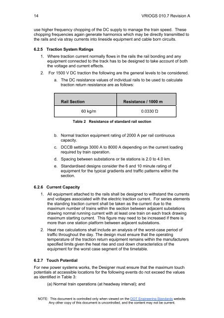
14 <strong>VRIOGS</strong> <strong>010.7</strong> Revision Ause higher frequency chopping of the DC supply to manage the train speed. Thesechopping frequencies again generate harmonics which may be directly transmitted tothe rails and via stray currents into lineside equipment and cable born circuits.6.2.5 Traction System Ratings1. Where traction current normally flows in the rails the rail bonding and anyequipment connected to the track has to be designed to take account of boththe voltage and current effects.2. For 1500 V DC traction the following are the general levels to be considered.a. The DC resistance values of individual rails to be used to calculatetraction return resistance are as follows:Rail SectionResistance / 1000 m60 kg/m 0.0330 ΏTable 2 Resistance of standard rail sectionb. Normal traction equipment rating of 2000 A per rail continuouscapacity.c. DCCB settings 3000 A to 8000 A depending on the current loadingrequired by train operation.d. Spacing between substations or tie stations is 2.0 to 4.0 km.e. Standardised designs consider the 6 and 10 minute rating ofequipment for the typical gradients and traffic patterns within thesection.6.2.6 Current Capacity1. All equipment attached to the rails shall be designed to withstand the currentsand voltages associated with the electric traction current. For series elementsthe standing traction current shall be taken as the current due to themaximum number of trains within the section between adjacent substationsdrawing normal running current with at least one train on each track drawingmaximum starting current. This figure may need to be increased if there ismore than one station platform between adjacent substations.2. Heat rise calculations shall include an analysis of the worst-case period oftraffic throughout the day. The design must ensure that the operatingtemperature of the traction return equipment remains within the manufacturersspecified limits given the heat rise and cool down characteristics of theequipment for the worst case segment of the timetable.6.2.7 Touch PotentialFor new power systems works, the Designer must ensure that the maximum touchpotentials at accessible locations for the following events do not exceed the valuesas identified in Table 3:(a) Normal train operations (at headway interval); andNOTE: This document is controlled only when viewed on the DOT Engineering Standards website.Any other copy of this document is uncontrolled, and the content may not be current.


