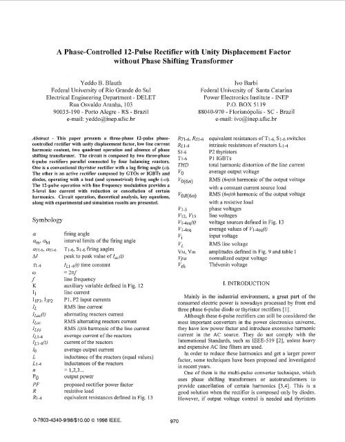
A Phase-Controlled 12-Pulse Rectifier with Unity ... - Ivo Barbi
A Phase-Controlled 12-Pulse Rectifier with Unity ... - Ivo Barbi
A Phase-Controlled 12-Pulse Rectifier with Unity ... - Ivo Barbi

Create successful ePaper yourself
Turn your PDF publications into a flip-book with our unique Google optimized e-Paper software.
+-.----<strong>Phase</strong> 1 current, of P1 (IlP1)‘ 1 1-----<strong>Phase</strong> 1 voltage (Vl)VabI,’.<strong>Phase</strong> 1 current ’1\ofP2 (IlP2)’ ;-m-., <strong>Phase</strong> 1 totalk‘--__-*4’”’.’.U-.’ ‘- #21 ,VI PhasorIlP2diagramFig. 6. Proposed rectifier modulation strategy.P2 is the well known 6-pulse phase-controlled rectifierfired in the usual way <strong>with</strong> a lag firing angle (a), while P1 isan active rectifier fired in the same way, but <strong>with</strong> a lead (andsymmetrical) firing angle (-a). Therefore, thyristors can beused in P2, and GTOs or IGBTs and diodes must be used inP 1, Fig. 7 shows the final proposed rectifier circuit.Fig. 8 shows P1 rectifier theoretical output voltage andinput current, the gate strategy, and how P1 works <strong>with</strong> a leadfiring angle. It can be noticed from Fig. 8 that any firing pulselasts <strong>12</strong>0°, and at each time only two switches are conducting(ON state).Fig. 8. P1 waveforms. From top to bottom: output voltage (Vab),phase 1 voltage (Vl), line voltages (V<strong>12</strong> and V13),phase 1 input current (IlPl) and firing pulses (Vgl to Vg6).At the tx instant an arbitrary commutation happens. It canbe concluded from the gate pulse pattern that immediatelybefore tx, TI and T5 arc ON, and after tx, T5 is OFF and TIand T6 are ON. After tx the output voltage (V13) is smallerthan before tx (VIZ), and it can not force any device to turnitself off. Therefore, natural commutation is impossible andself-extinction devices must be used in P 1.The modulation strategy has line frequency and, therefore,low switching losses. Fig. 6 also shows that the total inputcurrent has a complex waveform, and how current multilevelsare achieved. Because of the multi-levels of the inputcurrent, low harmonic content is expected.IV. RELEVANT ANALYSIS RESULTSFig. 7. Proposed rectifier circuit configuration.A. Output VoltageThe average output voltage of the proposed rectifier isgiven by (1).3Jzvo = -. v, . cos(a) (1)7rIt can be noticed that (1) is the same as that of thetraditional 6-pulse rectifier and the term “COS(CI)” explains thetwo quadrant operation.Fig. 9 shows the generic <strong>12</strong> quadrant output voltagewaveform when the load is a constant current source. It canbe noticed that there are three different 30° intervals in whichthe output voltage waveform varies in a different way.972
C. Currents of the ReactorsFig. <strong>12</strong> shows L2 and L1 voltage and current waveformsassuming Oo 5 a 5 60°, constant output current and perfectcurrent sharing among reactors.The ripple current of the reactors shown in Fig. <strong>12</strong> is causedby instantaneous differences between P1 and P2 outputvoltages, and its analysis allows the design of the reactors.v# 1L IFig. <strong>12</strong>. L2 and L1 voltages and currents assuming Oo< a 2 60°,constant output current and perfect current sharingamong reactors.It is convenient to separate the current of the reactors intwo parts: a direct current and an alternating current, likeshown in (7).10IL1-4(t) = -- + ILac(t)(7)2The average current of the reactors is given by (8).IOIL1-4 = 7LThe constant K defined in Fig. <strong>12</strong> is given by (9).K= 3. J2.VL .[sen(a)- a.cos(a)] (9)2.n.w. LThe voltage across the reactors reaches its maximum valueat a = 60° and, therefore, this is the worst case (a = 60°).The worst case peak to peak value ofIh,.# is given by (10).M=- &.V, (10)4.w. LThe worst case RMS value of l ~~~(t) is given by (1 1).0.1 07. VLILacW.LTo guarantee continuous conduction even in the worstcase, the inductance of the reactors is given by (<strong>12</strong>).0.462.V~L2@.IoD. Displacement Factor and Power FactorBecause of the adopted modulation strategy, the proposedrectifier has a unity displacement factor over the entireoperating band. The power factor is presented in Fig. 11 andis given by (1 3).PF= &.cos(a) Io (13)ILIV. CURRENT SHARING ANALYSISTo guarantee a correct operation of the proposed rectifier,the average current of the reactors must be equal.If the firing angle absolute value of all switches of eachrectifier are equal, if the amplitudes and the relative phases ofthe line voltages are equal, and if all switches, wires andbalancing reactors resistances and inductances are preciselyequal, then the proposed rectifier is composed by twoidentical rectifiers <strong>with</strong> symmetrical firing angles, and it canbe affirmed that the average current of the reactors will beexactly the same. In this case, there will be a perfect currentsharing between the two rectifiers (P1 and P2).Unfortunately, this is not the case in practical circuits.Small variations in any of the above mentioned quantities maycause unbalanced currents.To quantify these unbalanced currents it can be noticedfrom Fig. 8 and Fig. 13 that the proposed rectifier actually iscomposed by four different rectifiers: the upper (Tl, T2, T3;Vleq) and the bottom (T4, T5, T6; V4eq) P1 rectifiers, andthe upper (Sl, S2, S3; V2eq) and the bottom (S4, S5, S6;V3eq) P2 rectifiers.I m,Fig. 13. Proposed rectifier equivalent circuitBased on Fig. 13, the following equation can be written:From (14) it can be concluded that when the output currentis constant, the time evolution of the L1 reactor current Z~l(t)is governed by the time constant presented in (15). It can be974
also concluded that in a steady state, the average current ofthe L1 reactor is given by (16).Neglecting wire resistances and assuming equal linevoltages, the component values of the circuit of Fig. 13 areapproximately given by (1 7, 18).3.JT.vL COS(OTI) + co~(0j-2) + COS(OT~) (17)yecl 2*n - 3The equations to the other voltage sources and tothe other equivalent resistances (R2-4) are analogous to (17,18).To confirm the above analysis, Fig. 14 shows simulationresults where two reactors, one firing angle (an) and oneswitch equivalent resistance (RT6) are made purposivelydifferent. It can be concluded from Fig. 14 that the circuit hasonly two different time constants and all average currents ofthe reactors are different.1 OACURRENISof theREACTORSV. COMPARATIVE ANALYSISThe following graphics (figs. 15 and 16) are useful for acomparison between the proposed rectifier (normal lines) andthe well-known 6-pulse rectifier (broken lines). All of themhave in the horizontal axes the normalized ’output voltagedefined in (1 9).v,, =-- v0 -costa) (19)V0M.XIt can be concluded from Fig. 15 that for any outputvoltage, the RMS input harmonic current and, therefore, theRMS input current of the proposed rectifier are smaller thanthose of the 6-pulse rectifier.From Fig. 16 lit can be concluded that the proposedrectifier displacement and power factors are larger than thoseof the 6-pulse rectifier over the entire operating band. Thepower factor is PF == 0.985 when a = 15O and is always largerthan 0.95 in the usu,al operation band (Yo 2 VoMAX <strong>12</strong>).From figs. 15 and 16 it can be concluded that the overallperformance of the proposed rectifier is much better than thatof the 6-pulse one.Input currentHarmonic current03 I8A6A4AFig. 15. RMS normalized input current and RMS normalizedinput harmonic current of the proposed rectifier (normal lines) andthe 6-pulse rectifier (broken lines).Power factorDisplacement factor2ATIME0.5s I .os 1.5s 2.0sFig. 14. Simulation results of a forced unbalanced situation.VL = 155V, IO = 10A, TI = 58.30, a~2.6, = as14 = 64,80,RL1-4 = OQ, R~1-5 = RS1-6 = 0.8R, RT6 = 2.3R,L1,2 = 0.15H, L3,4 = 0.3H.Table 11 shows that simulation and theoretical results arequite similar.simul.theor.Table IT. Simulation and theoretical resultsr 1IL1 IL2 IL3 IL4 21,2 23,47.19A 2.81A 6.14A 3.86A 173ms 276ms7.17A 2.83A 6.19A 3.81A 187ms 286ms[,,’ , 1 I,--’ IU 0 5 I vpu (1 05 I vpuFig. 16. Power and displacement factors of the proposed rectifier(normal lines) and the 6-pulse rectifier (broken lines). .VI. EXPERIMENTAL RESULTSIn order to verity the theoretical analysis and the circuitoperation, a laboratory prototype <strong>with</strong> the followingspecifications has been built:Po=3kWVL = 380 V975
The output current can be estimated by:3.000%1, = ~=! 5.854“ o w (1.35)( 380)The inductance of the reactors was evaluated from (<strong>12</strong>):(0.462)( 380)L2L = 8OmH(2n.60)(5.85)The firing pulses of the P2 rectifier were generated <strong>with</strong>the scheme shown in Fig. 17. The PI lag firing pulse alsofires an upldown counter in the up position. When the linevoltage changes its signal, the counter begins to count down.PERCENTUALAMPLITUDEFig. 19. Harmonic analysis of the prototype input current.The harmonic analysis of the prototype input currentshown in Fig. 18 is presented in Fig. 19. It can be seen thatthe prototype has very low harmonic content.VII. CONCLUSIONFig. 17. P2 firing pulses generation scheme.The firing pulse of the P2 rectifier is generated when thecounter reaches zero. Because of the intrinsic symmetry of theline voltage, this scheme guarantees symmetric fring pulses.Fig. 18 shows experimental results obtained <strong>with</strong> theprototype that confirms the theoretical analysis.It can be concluded from Fig. 18 that the input current has5 different levels and a unity displacement factor. Themeasured power factor is PF = 0,974 and the total harmonicdistortion of the input current is THD = 20%, while thetheoretical values are PF = 0,983 and THD = 18,7%.In this paper, a three-phase controlled rectifier based on aparallel connection of two 6-pulse rectifiers has been presentedand analyzed. It was shown that the proposed rectifier has twoquadrant operation, low line current harmonic content, highpower factor and a much better overall performance than that ofthe 6-pulse rectifier.Simulation results have been presented to confirm theanalysis of the current sharing of the reactors andexperimental results have been included to demonstrate thefeasibility of the proposed circuit.It is the authors’ opinion that this new rectifier will findmany commercial and industrial applications mainly in themedium and high power range owing to its low frequencymodulation and its superior performance.REFERENCESRef4 300V Z.5OmsFig. 18 - Experimental results of a 3kW prototype feeding a 8OQresistive load <strong>with</strong> a firing angle a = 200. From top to bottom:output voltage and phase voltage (300V/div.), line current,conventional 6-pulse rectifier (P2) input current andactive rectifier (Pl) input current (5A/div.). Time in 2.5mddiv.[31141151171B.R.Pelly, “Thyristor <strong>Phase</strong>-<strong>Controlled</strong> Converters andCycloconverters” New York: Wiley-Interscience, 197 1.IEEE Std. 5 19-1992, “IEEE Recommended Practices andRequirements for Harmonic Control in Electrical PowerSystems”.J.Schaeffer, “<strong>Rectifier</strong> Circuits: Theory and Design” NewYork: Wiley-Interscience, 1965.D.A.Paice, “Power Electronic Converter Harmonics” IEEEPress, 1996.T.Kataoka, K.Kawakami, J.Kitano, “A <strong>Pulse</strong>width ModulatedAC to DC Converter Using Gate Turn-off Thyristors”, IEEEIAS Annual Meeting, pp 966 - 974, 1985.Y.Sato et al., “A New Control Strategy to Improve AC InputCurrent Waveform of High-Power Parallel Connected PWM<strong>Rectifier</strong>s”, IEEE PCC - Yokohama, 1993, pp.<strong>12</strong>9-134.M.Chandorkar, D.Divan, R.Lasseter, “Control Techniques forDual Current Source GTO Inverters”, Proc. of IEEE PowerConversion Conf - Yokohama, 1993, pp.659-665.H.Braga, I.<strong>Barbi</strong>, “A New Technique for Parallel Connectionof Commutation Cells: Analysis, Design and Experimentation”,Proceedings of the IEEE PESC, 1995, pp. 81-87.976