The Concept of Functional Virtual Prototype in the Design of ...
The Concept of Functional Virtual Prototype in the Design of ...
The Concept of Functional Virtual Prototype in the Design of ...

You also want an ePaper? Increase the reach of your titles
YUMPU automatically turns print PDFs into web optimized ePapers that Google loves.
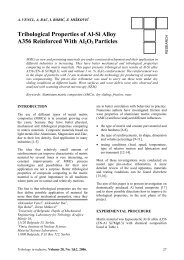
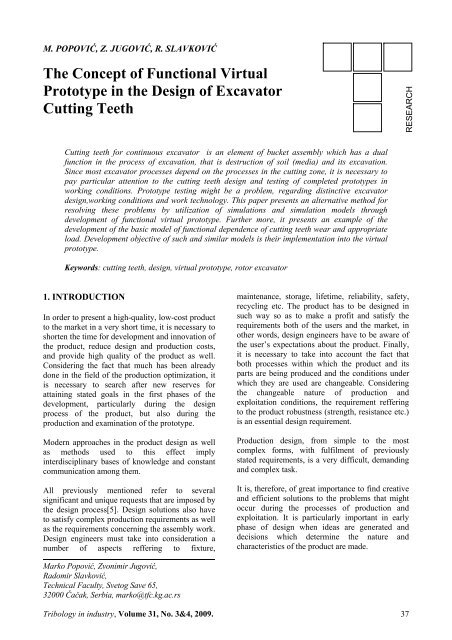
M. POPOVIĆ, Z. JUGOVIĆ, R. SLAVKOVIĆ<strong>The</strong> <strong>Concept</strong> <strong>of</strong> <strong>Functional</strong> <strong>Virtual</strong><strong>Prototype</strong> <strong>in</strong> <strong>the</strong> <strong>Design</strong> <strong>of</strong> ExcavatorCutt<strong>in</strong>g TeethRESEARCHCutt<strong>in</strong>g teeth for cont<strong>in</strong>uous excavator is an element <strong>of</strong> bucket assembly which has a dualfunction <strong>in</strong> <strong>the</strong> process <strong>of</strong> excavation, that is destruction <strong>of</strong> soil (media) and its excavation.S<strong>in</strong>ce most excavator processes depend on <strong>the</strong> processes <strong>in</strong> <strong>the</strong> cutt<strong>in</strong>g zone, it is necessary topay particular attention to <strong>the</strong> cutt<strong>in</strong>g teeth design and test<strong>in</strong>g <strong>of</strong> completed prototypes <strong>in</strong>work<strong>in</strong>g conditions. <strong>Prototype</strong> test<strong>in</strong>g might be a problem, regard<strong>in</strong>g dist<strong>in</strong>ctive excavatordesign,work<strong>in</strong>g conditions and work technology. This paper presents an alternative method forresolv<strong>in</strong>g <strong>the</strong>se problems by utilization <strong>of</strong> simulations and simulation models throughdevelopment <strong>of</strong> functional virtual prototype. Fur<strong>the</strong>r more, it presents an example <strong>of</strong> <strong>the</strong>development <strong>of</strong> <strong>the</strong> basic model <strong>of</strong> functional dependence <strong>of</strong> cutt<strong>in</strong>g teeth wear and appropriateload. Development objective <strong>of</strong> such and similar models is <strong>the</strong>ir implementation <strong>in</strong>to <strong>the</strong> virtualprototype.Keywords: cutt<strong>in</strong>g teeth, design, virtual prototype, rotor excavator1. INTRODUCTIONIn order to present a high-quality, low-cost productto <strong>the</strong> market <strong>in</strong> a very short time, it is necessary toshorten <strong>the</strong> time for development and <strong>in</strong>novation <strong>of</strong><strong>the</strong> product, reduce design and production costs,and provide high quality <strong>of</strong> <strong>the</strong> product as well.Consider<strong>in</strong>g <strong>the</strong> fact that much has been alreadydone <strong>in</strong> <strong>the</strong> field <strong>of</strong> <strong>the</strong> production optimization, itis necessary to search after new reserves foratta<strong>in</strong><strong>in</strong>g stated goals <strong>in</strong> <strong>the</strong> first phases <strong>of</strong> <strong>the</strong>development, particularly dur<strong>in</strong>g <strong>the</strong> designprocess <strong>of</strong> <strong>the</strong> product, but also dur<strong>in</strong>g <strong>the</strong>production and exam<strong>in</strong>ation <strong>of</strong> <strong>the</strong> prototype.Modern approaches <strong>in</strong> <strong>the</strong> product design as wellas methods used to this effect imply<strong>in</strong>terdiscipl<strong>in</strong>ary bases <strong>of</strong> knowledge and constantcommunication among <strong>the</strong>m.All previously mentioned refer to severalsignificant and unique requests that are imposed by<strong>the</strong> design process[5]. <strong>Design</strong> solutions also haveto satisfy complex production requirements as wellas <strong>the</strong> requirements concern<strong>in</strong>g <strong>the</strong> assembly work.<strong>Design</strong> eng<strong>in</strong>eers must take <strong>in</strong>to consideration anumber <strong>of</strong> aspects reffer<strong>in</strong>g to fixture,ma<strong>in</strong>tenance, storage, lifetime, reliability, safety,recycl<strong>in</strong>g etc. <strong>The</strong> product has to be designed <strong>in</strong>such way so as to make a pr<strong>of</strong>it and satisfy <strong>the</strong>requirements both <strong>of</strong> <strong>the</strong> users and <strong>the</strong> market, <strong>in</strong>o<strong>the</strong>r words, design eng<strong>in</strong>eers have to be aware <strong>of</strong><strong>the</strong> user’s expectations about <strong>the</strong> product. F<strong>in</strong>ally,it is necessary to take <strong>in</strong>to account <strong>the</strong> fact thatboth processes with<strong>in</strong> which <strong>the</strong> product and itsparts are be<strong>in</strong>g produced and <strong>the</strong> conditions underwhich <strong>the</strong>y are used are changeable. Consider<strong>in</strong>g<strong>the</strong> changeable nature <strong>of</strong> production andexploitation conditions, <strong>the</strong> requirement reffer<strong>in</strong>gto <strong>the</strong> product robustness (strength, resistance etc.)is an essential design requirement.Production design, from simple to <strong>the</strong> mostcomplex forms, with fulfilment <strong>of</strong> previouslystated requirements, is a very difficult, demand<strong>in</strong>gand complex task.It is, <strong>the</strong>refore, <strong>of</strong> great importance to f<strong>in</strong>d creativeand efficient solutions to <strong>the</strong> problems that mightoccur dur<strong>in</strong>g <strong>the</strong> processes <strong>of</strong> production andexploitation. It is particularly important <strong>in</strong> earlyphase <strong>of</strong> design when ideas are generated anddecisions which determ<strong>in</strong>e <strong>the</strong> nature andcharacteristics <strong>of</strong> <strong>the</strong> product are made.Marko Popović, Zvonimir Jugović,Radomir Slavković,Technical Faculty, Svetog Save 65,32000 Čačak, Serbia, marko@tfc.kg.ac.rsTribology <strong>in</strong> <strong>in</strong>dustry, Volume 31, No. 3&4, 2009. 37
2. INTEGRATED DESIGN APPROACH<strong>The</strong> aim <strong>of</strong> <strong>in</strong>tegrated approach is to shorten <strong>the</strong>development time and additionaly improve <strong>the</strong>product <strong>in</strong> this phase [6]. Realization <strong>of</strong> <strong>in</strong>tegratedapproach can be observed through simultaneousand virtual concept. Simultaneous concept is basedon need for close communication between designand technology. <strong>The</strong> po<strong>in</strong>t is that <strong>the</strong> product andtechnology development are simultaneous.Decisions concern<strong>in</strong>g <strong>the</strong> design process are madeon <strong>the</strong> basis <strong>of</strong> technology development and viceversa. In such a way <strong>the</strong> time for development isshortened and possible misunderstand<strong>in</strong>gsconcern<strong>in</strong>g <strong>the</strong> realization <strong>of</strong> proposed solutionsare avoided. <strong>Virtual</strong> concept is based on <strong>the</strong>unification <strong>of</strong> <strong>the</strong> product development <strong>in</strong> spaceand time. It is models, model<strong>in</strong>g and simulationthat represents <strong>the</strong> basics <strong>of</strong> <strong>the</strong> concept. <strong>The</strong>models are used to simulate <strong>the</strong> product, itsproperties, <strong>the</strong> production and <strong>the</strong> process <strong>of</strong>exploitation as well. <strong>The</strong> aim is unification <strong>of</strong> <strong>the</strong>simulation and its simultaneous realization fromseveral different aspects depend<strong>in</strong>g on <strong>the</strong> currentsubject <strong>of</strong> consideration.Figure 1. Classical V approach to design with <strong>the</strong> physical prototypes [1]It is physical prototype production and test<strong>in</strong>g thatis a bottleneck <strong>in</strong> almost every design process <strong>of</strong> anew constituent element <strong>of</strong> an cont<strong>in</strong>uousexcavator or <strong>in</strong> reconstruction <strong>of</strong> <strong>the</strong> exist<strong>in</strong>g ones.<strong>The</strong> question concern<strong>in</strong>g this issue has been raised.Cont<strong>in</strong>uous excavators are recognized as onesegment <strong>of</strong> <strong>the</strong> cont<strong>in</strong>uous excavation process and<strong>the</strong> process <strong>of</strong> coal transport. S<strong>in</strong>ce <strong>the</strong> process iscont<strong>in</strong>uous, if any element <strong>of</strong> <strong>the</strong> system does notwork, <strong>the</strong> entire l<strong>in</strong>e is out <strong>of</strong> order. Consider<strong>in</strong>g<strong>the</strong> fact that such systems are expected to workcont<strong>in</strong>ually, disregard for planned stoppages andoverhauls, any o<strong>the</strong>r stoppage would generateserious problems <strong>in</strong> terms <strong>of</strong> <strong>the</strong> satisfaction <strong>of</strong> <strong>the</strong>set requirements and it would also reflect oneconomic costs [9]. In addition, work<strong>in</strong>gconditions are quite unfavourable and <strong>the</strong>re is adanger concern<strong>in</strong>g large dimensions <strong>of</strong> rotorexcavator components, a danger regard<strong>in</strong>g workperformance and technology as well as currentcondition <strong>of</strong> <strong>the</strong> mach<strong>in</strong>e and her impact onprototype behaviour (e.g. prototype can be valid,however, due to relatively bad condition <strong>of</strong> <strong>the</strong>assembly or subassembly, it is not possible to getvalid results). We have to take <strong>in</strong>to account <strong>the</strong>quality and assembly work <strong>of</strong> <strong>the</strong> completedprototype as well as <strong>the</strong> impact that <strong>the</strong> prototype38breakdown has on ano<strong>the</strong>r mach<strong>in</strong>e elements (e.g.concurrent fracture <strong>of</strong> several cutt<strong>in</strong>g teeth cancause bucket damage). On <strong>the</strong> o<strong>the</strong>r hand,prototypes are pr<strong>in</strong>cipal <strong>in</strong>stances as <strong>the</strong>y have akey role <strong>in</strong> <strong>the</strong> f<strong>in</strong>al confirmation <strong>of</strong> <strong>the</strong> defaultsolution.Concern<strong>in</strong>g <strong>the</strong> above mentioned issues, it is <strong>of</strong> animmense importance to f<strong>in</strong>d an alternativeapproach to assembly work which would implyassembl<strong>in</strong>g <strong>of</strong> <strong>the</strong> physical prototype only when allpossible previous adjustments are made andafterwards tested and when all o<strong>the</strong>r possibilitiesare exhausted. A possible alternative lies <strong>in</strong> <strong>the</strong>development and application <strong>of</strong> <strong>the</strong> virtualprototype. Nowadays, virtual prototypes are usedfor better perception <strong>of</strong> future product appearanceeven at <strong>the</strong> early stage <strong>of</strong> development as well asfor simulation and test<strong>in</strong>g <strong>of</strong> <strong>the</strong> productcharacteristics before <strong>the</strong> production <strong>of</strong> physicalprototype. Thus, it is possible to achieve majoreconomies <strong>in</strong>, or even to elim<strong>in</strong>ate, costs and timeneeded for production and modification <strong>of</strong> physicalprototypes. Apart from visual representation <strong>of</strong> <strong>the</strong>product, virtual prototype has <strong>the</strong> task <strong>of</strong> descriptionand simulation <strong>of</strong> <strong>the</strong> product physical performance([4], [5]). As dist<strong>in</strong>guished from <strong>the</strong> physicalTribology <strong>in</strong> <strong>in</strong>dustry, Volume 31, No. 3&4, 2009.
prototypes, virtual prototypes make use <strong>of</strong> moderncomputer science, so <strong>the</strong> focus <strong>of</strong> design processshifts from physical to virtual environment, whichrepresents a significant advantage <strong>in</strong> resolv<strong>in</strong>gproblems concern<strong>in</strong>g strip m<strong>in</strong><strong>in</strong>g excavators.3. FUNCTIONAL VIRTUALPROTOTYPE<strong>The</strong> design process, known as process V (Figure 1.),consists <strong>of</strong> two clearly def<strong>in</strong>ed phases. <strong>The</strong> firstphase <strong>in</strong>cludes <strong>the</strong> top-down analysis that leads toa gradual and hierarchical def<strong>in</strong>ition <strong>of</strong> <strong>the</strong> systemfunctions and its components to <strong>the</strong> lowest level,i.e. <strong>the</strong> level <strong>of</strong> <strong>the</strong> basic physical exam<strong>in</strong>ation. <strong>The</strong>second phase <strong>in</strong>cludes systematically repeatedserial <strong>of</strong> corrected prototype tests up to a po<strong>in</strong>twhen <strong>the</strong> complete validation <strong>of</strong> <strong>the</strong> system hasbeen realized.Classical CA-x approach covers computersupported technologies aimed at <strong>the</strong> generation <strong>of</strong>product model, <strong>the</strong> analysis <strong>of</strong> its condition anddef<strong>in</strong>ition <strong>of</strong> necessary technological process<strong>in</strong>gparameters. Such approach is also known as “art topart”. Solutions atta<strong>in</strong>ed <strong>in</strong> such a way satisfyrequirements for solv<strong>in</strong>g <strong>the</strong> problem <strong>in</strong> <strong>the</strong> cases<strong>of</strong> less complex systems (products and processes)design. <strong>The</strong> notion <strong>of</strong> complexity is not related to<strong>the</strong> number and complexity <strong>of</strong> <strong>the</strong> components, butto <strong>the</strong> possibility and appropriate account <strong>of</strong> <strong>in</strong>nerand outer <strong>in</strong>teractions <strong>in</strong> <strong>the</strong> system. By generat<strong>in</strong>g<strong>the</strong> complex systems, whereat <strong>the</strong> elements areconnected through basic metaphysicalmanifestations on <strong>the</strong> lowest level, early defectidentification becomes practically impossible,<strong>the</strong>refore <strong>the</strong> success <strong>of</strong> <strong>the</strong> “first” design is hard toachieve. On <strong>the</strong> o<strong>the</strong>r hand, <strong>the</strong> later we perceive<strong>the</strong> problems dur<strong>in</strong>g test<strong>in</strong>g, <strong>the</strong> higher costs <strong>of</strong>correct<strong>in</strong>g <strong>the</strong>m are required (for example,perceiv<strong>in</strong>g errors <strong>in</strong> l<strong>in</strong>k<strong>in</strong>g components <strong>of</strong> <strong>the</strong>cutt<strong>in</strong>g tooth is more convenient than perceiv<strong>in</strong>gproblems <strong>in</strong> versification <strong>of</strong> <strong>the</strong> adopted concept <strong>of</strong><strong>the</strong> cutt<strong>in</strong>g tooth). Fur<strong>the</strong>rmore, it should bepo<strong>in</strong>ted out that <strong>the</strong> problem <strong>of</strong> build<strong>in</strong>g optimalsystem on <strong>the</strong> whole cannot be solved by optimaldesign <strong>of</strong> certa<strong>in</strong> components <strong>of</strong> <strong>the</strong> system.<strong>The</strong>refore it is necessary to def<strong>in</strong>e new horizons <strong>in</strong><strong>the</strong> field <strong>of</strong> <strong>the</strong> exist<strong>in</strong>g technologies and steptowards new ones. It is feasible to be done bydevelopment <strong>of</strong> new devices as well as <strong>in</strong>tegrationand modification <strong>of</strong> <strong>the</strong> exist<strong>in</strong>g technologies, suchas CAD/CAM/CAE, so that <strong>the</strong> subject <strong>of</strong> <strong>the</strong>irexam<strong>in</strong>ation might be extended to a complexsystem.Figure 2. <strong>The</strong> diagram <strong>of</strong> <strong>the</strong> <strong>Functional</strong> <strong>Virtual</strong> <strong>Prototype</strong> concept [2]<strong>The</strong> concept <strong>Functional</strong> <strong>Virtual</strong> <strong>Prototype</strong> – FVP(Figure 2.) enables perceiv<strong>in</strong>g not only <strong>the</strong> functions<strong>of</strong> some <strong>of</strong> its components, but also <strong>the</strong> function <strong>of</strong><strong>the</strong> entire system and its operative performances.<strong>The</strong> approach based on FVP is a range <strong>of</strong> wellorganizedtasks used <strong>in</strong> <strong>the</strong> design process or <strong>the</strong>process <strong>of</strong> improv<strong>in</strong>g <strong>the</strong> exist<strong>in</strong>g system throughconstruct<strong>in</strong>g separate models that describe <strong>the</strong>system. By <strong>the</strong> analysis <strong>of</strong> <strong>the</strong> system functionsand categorization performed <strong>in</strong> accordance with<strong>the</strong> specification <strong>of</strong> <strong>the</strong> realization, a complexmodel that provides better comprehension <strong>of</strong> itsTribology <strong>in</strong> <strong>in</strong>dustry, Volume 31, No. 3&4, 2009. 39
essential mean<strong>in</strong>g can be built. Basically, thisconcept is founded on <strong>the</strong> descriptive andpredicative models <strong>of</strong> <strong>the</strong> objects, parts <strong>of</strong> <strong>the</strong>systems and <strong>the</strong>ir environment. Thus, computersimulation and test<strong>in</strong>g are placed <strong>in</strong> <strong>the</strong> foreground,whereas physical production and test<strong>in</strong>g are usedas utmost tools for design versification andimprovement <strong>of</strong> <strong>the</strong> simulation models.4. BASIC ELEMENTS NECESSARY FORGENERATON OF THE VIRTUALPROTOTYPE<strong>The</strong> most important task <strong>of</strong> <strong>the</strong> virtual prototype isa complete conveyance <strong>of</strong> design, production,development and test<strong>in</strong>g phases on a computer,which would considerably reduce <strong>the</strong> time andcosts <strong>of</strong> product development. Without dist<strong>in</strong>ction<strong>of</strong> what type <strong>of</strong> functional virtual prototype it isabout, i.e. no matter what process or system ismodelled, <strong>the</strong> follow<strong>in</strong>g phases <strong>in</strong> construction <strong>of</strong>such models can be def<strong>in</strong>ed [5]:1. Production2. Test<strong>in</strong>g (test<strong>in</strong>g simulations)3. Estimation4. Development5. Automation<strong>Design</strong> <strong>of</strong> <strong>the</strong> system virtual prototype (<strong>of</strong> <strong>the</strong>product, process etc.) is completed <strong>in</strong> <strong>the</strong> firstphase. In this phase structure def<strong>in</strong><strong>in</strong>g anddis<strong>in</strong>tegration <strong>in</strong>to <strong>in</strong>tegral subsystems andcomponents are performed. Clear correlationsestablished between <strong>the</strong> <strong>in</strong>tegral components at thisstage enable <strong>the</strong> development <strong>of</strong> true and complexmodel with possible variations. For example,geometry and mass features <strong>of</strong> separatecomponents <strong>of</strong> <strong>the</strong> cutt<strong>in</strong>g elements can be atta<strong>in</strong>edfrom solid models, whereas mechanicalcharacteristics can be achieved from componentmodels <strong>of</strong> <strong>the</strong> def<strong>in</strong>ite elements or fromexperimental test<strong>in</strong>g.One <strong>of</strong> <strong>the</strong> significant phases <strong>in</strong>cludes formation <strong>of</strong><strong>the</strong> virtual equivalent for laboratory test<strong>in</strong>g andtest<strong>in</strong>g <strong>in</strong> <strong>the</strong> field. With<strong>in</strong> laboratory test<strong>in</strong>g, <strong>the</strong>virtual prototype requires <strong>in</strong>stallation <strong>of</strong> <strong>the</strong> virtualtest equipment for procedure reproduction andreproduction <strong>of</strong> conditions realized by <strong>the</strong>utilization <strong>of</strong> real appliances and test<strong>in</strong>g mach<strong>in</strong>es.<strong>The</strong>reupon, test constitution reflect<strong>in</strong>g actual orneeded exploitation conditions are performed.Figure 3. Synoptic diagram <strong>of</strong> <strong>the</strong> FVP for bucket wheel excavators40Tribology <strong>in</strong> <strong>in</strong>dustry, Volume 31, No. 3&4, 2009.
At <strong>the</strong> next stage model estimation is performed,i.e. virtual and physical model are tested <strong>in</strong> <strong>the</strong>identical manner, and afterwards comparison anddeduction are performed. By additional adjustment<strong>of</strong> <strong>the</strong> virtual test we achieve a reliable model forfur<strong>the</strong>r test<strong>in</strong>g.In <strong>the</strong> process <strong>of</strong> <strong>the</strong> virtual prototype utilization,its development and improvement are carried out,with<strong>in</strong> which simpler <strong>in</strong>itial virtual prototypes arecomposed <strong>in</strong>to complex functional virtualprototypes. Thus, modular solutions that cansignificantly expand activity field <strong>of</strong> <strong>the</strong> basicvirtual prototype are obta<strong>in</strong>ed, whereat fur<strong>the</strong>radjustments refer only to some newly-addedsegments (e.g. <strong>in</strong> <strong>the</strong> process <strong>of</strong> bucket test<strong>in</strong>gwhereat not only cutt<strong>in</strong>g teeth but special blades <strong>in</strong>a form <strong>of</strong> a knife are added as well. Concern<strong>in</strong>gthis, VM teeth buckets can be used with anaddition <strong>of</strong> new modules that are later adjusted).Improvement is always carried out <strong>in</strong> twodirections, <strong>in</strong> <strong>the</strong> direction <strong>of</strong> improvement <strong>of</strong> <strong>the</strong>model accuracy and constancy, and <strong>in</strong> <strong>the</strong> direction<strong>of</strong> improvement <strong>of</strong> <strong>the</strong> product design.<strong>The</strong> f<strong>in</strong>al phase <strong>of</strong> <strong>the</strong> design is process automation<strong>of</strong> <strong>the</strong> virtual prototype construction. It is onlywhen enough “knowledge” and “experience” <strong>in</strong>exist<strong>in</strong>g models are generated, that we canapproach this phase. Current generation <strong>of</strong> newsimilar constructions is achieved by <strong>the</strong> automation<strong>in</strong> a short time. Thus <strong>the</strong> structure and mostcomponents are “lent”, whereas adjustments referonly to those segments that have difference fornew and exist<strong>in</strong>g design. <strong>The</strong> utilization <strong>of</strong> FVPcan be automated only when one completed,through many cycles estimated model <strong>of</strong> <strong>the</strong> virtualprototype exists and when it is tuned through <strong>the</strong>change <strong>of</strong> its characteristic parameters.5. WEAR MODEL OF CUTTING TEETH<strong>The</strong> follow<strong>in</strong>g text presents an example <strong>of</strong> a modeldef<strong>in</strong><strong>in</strong>g that connects cutt<strong>in</strong>g elements load with<strong>the</strong> extent <strong>of</strong> <strong>the</strong>ir wear. When we talk about a part<strong>of</strong> <strong>the</strong> cutt<strong>in</strong>g tooth wear and <strong>the</strong>ir <strong>in</strong>fluence on <strong>the</strong>process <strong>of</strong> cutt<strong>in</strong>g soil, we talk about <strong>the</strong> enormousconsumption <strong>of</strong> materials <strong>in</strong> two characteristicplaces. <strong>The</strong> first one is <strong>the</strong> tooth-face wear, whichis a consequence <strong>of</strong> excavated material <strong>in</strong>fluence.<strong>The</strong> second is <strong>the</strong> dorsal surface wear, which is aconsequence <strong>of</strong> <strong>the</strong> <strong>in</strong>teraction between back part<strong>of</strong> <strong>the</strong> tooth and <strong>the</strong> forehead <strong>of</strong> <strong>the</strong> excavatedmaterial block. In general, <strong>the</strong> worn wedge-shapedtool with f<strong>in</strong>ished width, as shown <strong>in</strong> <strong>the</strong> Figure 4.,can be approximately assumed.Figure 4. Wear model <strong>of</strong> <strong>the</strong> cutt<strong>in</strong>g teeth<strong>The</strong> Figure 4., presents <strong>the</strong> follow<strong>in</strong>g variables: α -cutt<strong>in</strong>g angle, β - wedge angle, γ - relief angle, δ -angle <strong>of</strong> tooth wear, δ st =β+γ, F trL - frictional force(resistance) on <strong>the</strong> dorsal surface <strong>of</strong> <strong>the</strong> tooth, F nL -a normal component <strong>of</strong> <strong>the</strong> frictional force on <strong>the</strong>dorsal surface <strong>of</strong> <strong>the</strong> tooth, F trG – frictional force(resistance) on <strong>the</strong> tooth-face, F nG - a normalcomponent <strong>of</strong> <strong>the</strong> frictional force on <strong>the</strong> tooth-face,a – wear length, s – thrust length. <strong>The</strong> forcesdef<strong>in</strong>ed by this model are valid only with <strong>the</strong>follow<strong>in</strong>g hypo<strong>the</strong>sis:a) <strong>The</strong> force function F nG is a feature <strong>of</strong> <strong>the</strong>excavated material and it is proportional to <strong>the</strong>tooth-face (A G =b⋅h): FnG= b ⋅ h ⋅ kB,whereat: b – is <strong>the</strong> width <strong>of</strong> <strong>the</strong> cutt<strong>in</strong>g blade,k B – is <strong>the</strong> specific resistance to chipproductions [kN/m 2 ], h – is <strong>the</strong> thickness <strong>of</strong><strong>the</strong> chip .b) On <strong>the</strong> basis <strong>of</strong> <strong>the</strong> wedge effect and previouslygenerated crack that is typical for brittlebreak<strong>in</strong>g with a small deformation <strong>of</strong> <strong>the</strong> soil(<strong>the</strong> <strong>in</strong>itial destruction phase has beencompleted), <strong>the</strong> direction <strong>of</strong> <strong>the</strong> force effect F nGlies close to <strong>the</strong> perpendicular to <strong>the</strong> motionpath (Figure 4.).c) Ei<strong>the</strong>r elastic or plastic deformation <strong>of</strong> <strong>the</strong>excavated material occurr<strong>in</strong>g on <strong>the</strong> backside<strong>of</strong> <strong>the</strong> wear surface, br<strong>in</strong>gs about <strong>the</strong> force F nL ,a characteristic <strong>of</strong> <strong>the</strong> material itself,represented as <strong>the</strong> function <strong>of</strong> <strong>the</strong> penetrativedepth s: FnL= b ⋅ a ⋅ s ⋅ kv, whereat b – is <strong>the</strong>width <strong>of</strong> <strong>the</strong> cutt<strong>in</strong>g blade, k v – is <strong>the</strong> specificresistance <strong>of</strong> <strong>the</strong> wear surface. [kN/m 3 ]d) Direction <strong>of</strong> force F nL lies perpendicularly to <strong>the</strong>wear surface or it is <strong>in</strong>cl<strong>in</strong>ed at an angle <strong>in</strong> regardto <strong>the</strong> perpendicular (<strong>in</strong> this case <strong>the</strong> force on <strong>the</strong>top <strong>of</strong> <strong>the</strong> tooth is taken <strong>in</strong>to consideration).e) <strong>The</strong> wear specific resistances are values thatshould be determ<strong>in</strong>ed and <strong>the</strong>y present <strong>the</strong>function <strong>of</strong> <strong>the</strong> excavated materialcharacteristic.Tribology <strong>in</strong> <strong>in</strong>dustry, Volume 31, No. 3&4, 2009. 41
f) <strong>The</strong> presented tooth model should beobserved <strong>in</strong> <strong>the</strong> plane that has been <strong>in</strong>cl<strong>in</strong>ed atsome angle (ε) <strong>in</strong> relation to <strong>the</strong> movementdirection. Ow<strong>in</strong>g to <strong>the</strong> angle, <strong>the</strong> frictionalforces would not lie <strong>in</strong> <strong>the</strong> plane <strong>of</strong> <strong>the</strong> wedge.Consequently, this angle is a result <strong>of</strong> <strong>the</strong>teeth arrangement <strong>in</strong> <strong>the</strong> bucket and currentposition <strong>of</strong> <strong>the</strong> exam<strong>in</strong>ed tooth <strong>in</strong> <strong>the</strong>movement trajectory (sequence rotation <strong>of</strong> <strong>the</strong>work<strong>in</strong>g wheel and swerv<strong>in</strong>g <strong>the</strong> arrowexcavator).By observ<strong>in</strong>g <strong>the</strong> previous figure, it is possible toprovide an analysis <strong>of</strong> <strong>the</strong> forces. Exam<strong>in</strong>ation <strong>of</strong><strong>the</strong> model <strong>in</strong> <strong>the</strong> plane is enabled by <strong>the</strong>decomposition <strong>of</strong> <strong>the</strong> act<strong>in</strong>g forces <strong>in</strong>to adequatecomponents (Figure 5.).When we look at Figure 5., and results obta<strong>in</strong>edfrom <strong>the</strong> research [7], it is evident that <strong>the</strong> normalforce F N must represent sum <strong>of</strong> two forces, and<strong>the</strong>se are a force exerted from chip generates abovetooth-face and <strong>the</strong> o<strong>the</strong>r exerted from wear surfaceeffect on relief tooth surface, which acts even <strong>in</strong> <strong>the</strong>case <strong>of</strong> „sharp“ teeth due to blade radius andexcavated material structure. This „additional“ forceand force <strong>of</strong> friction caused by it are notproportional to <strong>the</strong> dimensions <strong>of</strong> chips but to wearsurface. Wear angle δ can be considered constantfor one cycle <strong>of</strong> <strong>the</strong> teeth wear. <strong>The</strong> size <strong>of</strong> thisangle depends on: design parameters <strong>of</strong> <strong>the</strong> teeth,type <strong>of</strong> excavated material, excavator worktechnology, bucket characteristics regard<strong>in</strong>gassembly work etc.Figure 5. Example <strong>of</strong> decomposition <strong>of</strong> <strong>the</strong> act<strong>in</strong>gforces<strong>The</strong> represented model takes <strong>in</strong>to considerationfunctions <strong>of</strong> <strong>the</strong> average values. Basically, <strong>the</strong>function differs from <strong>the</strong> model <strong>of</strong> soil failure,never<strong>the</strong>less it is applicable <strong>in</strong> this place due toexam<strong>in</strong>ation <strong>of</strong> <strong>the</strong> conditions describ<strong>in</strong>g <strong>the</strong>process <strong>in</strong> <strong>the</strong> “middle”, not to <strong>the</strong> exam<strong>in</strong>ation <strong>of</strong><strong>the</strong> current conditions.Observ<strong>in</strong>g <strong>the</strong> plane model, determ<strong>in</strong>ed bydirections <strong>of</strong> <strong>the</strong> tangential and perpendicularforce, <strong>in</strong> relation to <strong>the</strong> forces def<strong>in</strong><strong>in</strong>g with<strong>in</strong> rotorexcavator, accord<strong>in</strong>g to <strong>the</strong> Figure 5., <strong>the</strong> follow<strong>in</strong>gexpressions can be def<strong>in</strong>ed:FFtrLtrG= μ ⋅FLGnL= μ ⋅ FnG→F→FrLrG→= F→= FtrLtrG→+ F→+ FnLnG→= F→= FTLTG→+ F→+ FNLNGFigure 6. Measured force load for a s<strong>in</strong>gle tooth(laboratory model)42Tribology <strong>in</strong> <strong>in</strong>dustry, Volume 31, No. 3&4, 2009.
In accordance with previously shown equations,we can notice <strong>the</strong> mutual dependence <strong>of</strong> <strong>the</strong> size <strong>of</strong><strong>the</strong> wear surface and a component which <strong>in</strong>creases<strong>the</strong> total excavation resistance. Diagrams (Figure6.) show <strong>the</strong> results <strong>of</strong> realized measur<strong>in</strong>gs thattestify previous statement. All three components <strong>of</strong>excavation resistance are measured with<strong>in</strong>laboratory test<strong>in</strong>g. With regard to <strong>the</strong> subject <strong>of</strong>this paper, it is more important to exam<strong>in</strong>e trendsand relative ratio <strong>of</strong> <strong>the</strong> obta<strong>in</strong>ed results thanapsolute value <strong>of</strong> <strong>the</strong> obta<strong>in</strong>ed resistances. <strong>The</strong>conclusion that may be drawn is that <strong>the</strong> <strong>in</strong>crease<strong>of</strong> wear surface leads to <strong>the</strong> <strong>in</strong>crease <strong>of</strong> totalrequired cutt<strong>in</strong>g force, for it is necessary to<strong>in</strong>crease <strong>the</strong> cutt<strong>in</strong>g force whereas <strong>the</strong> soil stressfailure rema<strong>in</strong>s unaltered.Table 1. Measured values for previous diagramsL 1 δ st =35° δ=0° a=0 mmL 2 δ st =35° δ=5° a=7 mmL 3 δ st =55° δ=0° a=0 mmL 4 δ st =55° δ=5° a=8.5 mm<strong>The</strong> model shown on Figures 4.,5., represent a basefor connect<strong>in</strong>g cutt<strong>in</strong>g teeth load with parameters<strong>of</strong> its wear. In such a way, variations and possibleappearances <strong>of</strong> wear surface and its dimensionswould represent <strong>the</strong> <strong>in</strong>put, and <strong>the</strong> output would be<strong>the</strong> load <strong>of</strong> cutt<strong>in</strong>g elements and o<strong>the</strong>r elements <strong>of</strong><strong>the</strong> rotor excavator system. <strong>The</strong> aim <strong>of</strong> <strong>the</strong>development <strong>of</strong> such and similar models is <strong>the</strong>irimplementation <strong>in</strong> functional virtual prototype. <strong>The</strong>next figure shows a model which <strong>of</strong>fers aparametric def<strong>in</strong>ition <strong>of</strong> <strong>the</strong> cutt<strong>in</strong>g teeth wear [8].Figure 7. Example <strong>of</strong> parametric values forcutt<strong>in</strong>g teeth wear6. CONCLUSION<strong>The</strong> paper presents <strong>the</strong> application <strong>of</strong> <strong>the</strong> concept<strong>of</strong> functional virtual prototype <strong>in</strong> <strong>the</strong> development<strong>of</strong> cutt<strong>in</strong>g teeth for <strong>the</strong> cont<strong>in</strong>uous excavator. Initialmodel is s<strong>in</strong>gled out and described as an example.It is this model that establishes connection between<strong>the</strong> load and <strong>the</strong> degree and form <strong>of</strong> cutt<strong>in</strong>g toothwear. It represents only one segment that is to beused for complex virtual prototype generat<strong>in</strong>g.Such approach <strong>in</strong> <strong>the</strong> development <strong>of</strong> a newgeneration <strong>of</strong> teeth used for cont<strong>in</strong>uous excavatorswould br<strong>in</strong>g about <strong>the</strong> follow<strong>in</strong>g positive effects:• Risk m<strong>in</strong>imization concern<strong>in</strong>g <strong>the</strong> failure <strong>of</strong> <strong>the</strong>teeth conception and its f<strong>in</strong>al design• Time required for <strong>the</strong> prototype developmentand test<strong>in</strong>g would be shortened• <strong>The</strong> number <strong>of</strong> repetitive steps with<strong>in</strong> andbetter organization <strong>of</strong> design and test<strong>in</strong>gprocesses• Improved reliability <strong>of</strong> design process• Test<strong>in</strong>g <strong>of</strong> similar structures would also bepossible to carry out repeatedly and <strong>the</strong>rewould be a possibility for o<strong>the</strong>r excavatorcomponents to be testedREFERENCES[1] Herve, Y., Desgreys, P., <strong>Functional</strong> virtualprototyp<strong>in</strong>g design flow and VHDL-AMS,Forum on specification & <strong>Design</strong> Languages(FDL'06), Darmstadt (Germany), September19-22, pp. 69-76, 2006[2] Legendre, A., Herve, Y., <strong>Functional</strong> <strong>Virtual</strong>Prototyp<strong>in</strong>g Applied to Medical DevicesDevelopment, Systems VIP, Strasbourg, 2008.[3] Ryan, R., Digital test<strong>in</strong>g <strong>in</strong> <strong>the</strong> context <strong>of</strong>digital eng<strong>in</strong>eer<strong>in</strong>g - <strong>Functional</strong> <strong>Virtual</strong>Prototyp<strong>in</strong>g, Mechanical Dynamics, Inc.,Michigan, USA, 1999.[4] Mandić, V., Virtuelni <strong>in</strong>ženjer<strong>in</strong>g, Maš<strong>in</strong>skifakultet, Kragujevac, 2007[5] Kolarević, M., Brzi razvoj proizvoda,Beograd, Zadužb<strong>in</strong>a Andrejević, 2004.[6] Ognjanović, M., Konstruisanje maš<strong>in</strong>a,Maš<strong>in</strong>ski fakultet, Beograd, 2003.[7] Hitzschke, K., Jacob, K., ExperimentelleAnalyse der Belastung des Schaufelrades durchden Grabvorgang, Teil 1,2, Hebezeuge undFördermittel 24, Berl<strong>in</strong>, 1984.[8] Popović, M., Jugović, Z., Slavković, R.,Integrisani pristup konstruisanja habajućihreznih elemenata kod rotornih bagera,Serbiatrib’07, Kragujevac, 2007[9] Popović, M., Istraživanje i razvoj dvodelnekonstrukcije zuba kod rotornih bagera,Magistarski rad, Tehnički fakultet, Čačak, 2007.[10] Franek, F., Vorlaufer, G., Edelbauer, W.,Bukovnik, S., Simulation <strong>of</strong> Tribo systems andTribometrology, Tribology <strong>in</strong> <strong>in</strong>dustry,Vol.29, No.1&2,2007.[11] Ivković, B., Tribološke površ<strong>in</strong>e u tribomehaničkimsistemima, Tribology <strong>in</strong> <strong>in</strong>dustry,Vol.21, No.2, 1999.Tribology <strong>in</strong> <strong>in</strong>dustry, Volume 31, No. 3&4, 2009. 43
44Tribology <strong>in</strong> <strong>in</strong>dustry, Volume 31, No. 3&4, 2009.