OLIMEXINO-32U4 development board USER'S MANUAL
OLIMEXINO-32U4 development board USER'S MANUAL
OLIMEXINO-32U4 development board USER'S MANUAL

You also want an ePaper? Increase the reach of your titles
YUMPU automatically turns print PDFs into web optimized ePapers that Google loves.
OLIMEX© 2012<strong>OLIMEXINO</strong>-<strong>32U4</strong> User's ManualCHAPTER 1OVERVIEW1. Introduction to the chapterThank you for choosing the <strong>OLIMEXINO</strong>-<strong>32U4</strong> <strong>development</strong> <strong>board</strong> from Olimex! This documentprovides a User’s Guide for the Olimex <strong>OLIMEXINO</strong>-<strong>32U4</strong> <strong>development</strong> <strong>board</strong>. As an overview,this chapter gives the scope of this document and lists the <strong>board</strong>’s features. The document’sorganization is then detailed.The <strong>OLIMEXINO</strong>-<strong>32U4</strong> <strong>development</strong> <strong>board</strong> enables code <strong>development</strong> of applications running onthe ATMega<strong>32U4</strong> microcontroller, manufactured by Microchip technology.1.1 Features• Leonardo design – no FTDI chip, the MCU directly handles the virtual COM• ATMEGA<strong>32U4</strong> microcontroller, all in one USB communication no need for external FTDIchip.• Input power supply 7-12VDC• ULTRA LOW POWER voltage regulators and the consumption is only few microamps,which enables handheld and battery powered applications.• Li-Ion rechargable battery power supply option with BUILD-IN on <strong>board</strong> charger, so whenyou attach battery it is automatically charged and kept in this state until the other powersource (USB or external adapter) is removed and it AUTOMATICALLY will power the<strong>board</strong> - no jumpers, no switches!• Works both on 3.3V and on 5V which is selectable with jumper, so 3.3V and 5V shields canbe used• UEXT connector which allow many existing modules like RF, ZIGBEE, GSM, GPS to beconnected• Allows RTC - Real Time Clock.• NOISE IMMUNE design• the LEDs and the BUTTONs are on the edge of the <strong>board</strong> so there is easy access even if the<strong>board</strong>s have shields on them• all components are LOWER than the connectors, so the shields do not interference withthem• mini USB connector is used which is common and used in most cell phones, so you do nothave to buy other cablesPage 5 of 29
OLIMEX© 2012<strong>OLIMEXINO</strong>-<strong>32U4</strong> User's Manual• Original design had flaw and the connectors were not spaced at 0.1" this make perfo <strong>board</strong>use impossible, to keep the compatibility we have same spacing but we add next to thisconnector on 0.1" which customer can use with perforated <strong>board</strong>s• All signals on the connectors are printed on top and on bottom of the <strong>board</strong>, so when youcheck with probe you know exactly which port you are measuring• 4 mount holes make <strong>board</strong> attachment easier1.2 Similar <strong>board</strong>s<strong>OLIMEXINO</strong>-<strong>32U4</strong> is ARDUINO-LEONARDO-like <strong>board</strong> with ATMega<strong>32U4</strong>.It is a powerful <strong>board</strong> considering its low price but yet a starter <strong>board</strong> for the Arduino family.The more powerful Arduino <strong>board</strong> we have in the range is <strong>OLIMEXINO</strong>-328 – based on ArduinoDuenomilanove. It has a more sophisticated supply circuit, USB OTG connector and there are moreArduino projects available.1.3 OrganizationEach section in this document covers a separate topic, organized as follow:– Chapter 1 is an overview of the <strong>board</strong> usage and features– Chapter 2 has a short introduction to Arduino platform and its derivatives Pinguino andMaple– Chapter 3 provides a guide for quickly setting up the <strong>board</strong>– Chapter 4 contains the general <strong>board</strong> diagram and layout– Chapter 5 describes the component that is the heart of the <strong>board</strong>: the ATMega<strong>32U4</strong>microcontroller– Chapter 6 is an explanation of the control circuitry associated with the microcontroller toreset. Also shows the clocks on the <strong>board</strong>– Chapter 7 covers the connector pinout, peripherals and jumper description– Chapter 8 shows the processor diagram and memory map– Chapter 9 provides the schematics– Chapter 10 contains the revision historyPage 6 of 29
OLIMEX© 2012<strong>OLIMEXINO</strong>-<strong>32U4</strong> User's ManualCHAPTER 3SETTING UP THE <strong>OLIMEXINO</strong>-<strong>32U4</strong> BOARD3. Introduction to the chapterThis section helps you set up the <strong>OLIMEXINO</strong>-<strong>32U4</strong> <strong>development</strong> <strong>board</strong> for the first time.Please consider first the electrostatic warning to avoid damaging the <strong>board</strong>, then discover thehardware and software required to operate the <strong>board</strong>.The procedure to power up the <strong>board</strong> is given, and a description of the default <strong>board</strong> behavior isdetailed.3.1 Electrostatic warning<strong>OLIMEXINO</strong>-<strong>32U4</strong> is shipped in a protective anti-static package. The <strong>board</strong> must not be exposedto high electrostatic potentials. A grounding strap or similar protective device should be worn whenhandling the <strong>board</strong>. Avoid touching the component pins or any other metallic element.3.2 RequirementsIn order to set up the <strong>OLIMEXINO</strong>-<strong>32U4</strong>, the following items are required:If using the free ARDUINO IDE the ONLY requirement is a miniUSB to USB-A cable to connectto a computer.If you want to upgrade the bootloader, or program the <strong>board</strong> without the ARDUINO-IDE there arepinouts for ICSP programmer (note that there isn't a connector mounted). You can use our AVR-ISP-ISO, or AVR-ISP-TINY programmer for custom programming without ARDUINO IDE.Having an AVR programmer is highly advisable since the bootloader software is still not perfectand it is possible to destroy it only by software means (remap pins used for programming) whichwould require reinstalling the bootloader.3.3 Powering the <strong>board</strong>The <strong>OLIMEXINO</strong>-<strong>32U4</strong> <strong>board</strong> is self-powered by the miniUSB if it is connected to a USB hub of aPage 10 of 29
OLIMEX© 2012<strong>OLIMEXINO</strong>-<strong>32U4</strong> User's Manualcomputer.Alternatively it can be powered via the POWER JACK by 7Vdc to 12Vdc or via the 3.7V-LI_BATconnector by 3.7V battery.The bootloader starts automatically.On powering the <strong>board</strong> PWR_LED should turn on. RXLED and TXLED should turn on andmonitor the send receive on the virtual COM port. LED1 and LED2 should start blinking.3.4 Prebuilt softwareThe <strong>board</strong> comes with prebuilt ARDUINO bootloader. The different part between the otherArduinos and Leonardo is that Leonardo doesn't use FTDI chip nor external chip for the virtualCOM port but it is handled by the ATMega<strong>32U4</strong>.Page 11 of 29
OLIMEX© 2012<strong>OLIMEXINO</strong>-<strong>32U4</strong> User's ManualCHAPTER 4<strong>OLIMEXINO</strong>-<strong>32U4</strong> BOARD DESCRIPTION4. Introduction to the chapterHere you get acquainted with the main parts of the <strong>board</strong>. Note the names used on the <strong>board</strong> differfrom the names used to describe them. For the actual names check the <strong>OLIMEXINO</strong>-<strong>32U4</strong> <strong>board</strong>itself.4.1 Layout (top view)Page 12 of 29
OLIMEX© 2012<strong>OLIMEXINO</strong>-<strong>32U4</strong> User's ManualCHAPTER 5THE ATMEGA<strong>32U4</strong> MICROCONTROLLER5. Introduction to the chapterIn this chapter is located the information about the heart of <strong>OLIMEXINO</strong>-<strong>32U4</strong> – itsmicrocontroller. The information is a modified version of the datasheet provided by itsmanufacturers.5.1 The microcontroller's features• High Performance, Low Power AVR® 8-Bit Microcontroller• Advanced RISC Architecture– 135 Powerful Instructions – Most Single Clock Cycle Execution– 32 x 8 General Purpose Working Registers– Fully Static Operation– Up to 16 MIPS Throughput at 16 MHz– On-Chip 2-cycle Multiplier• Non-volatile Program and Data Memories– 32K Bytes of In-System Self-Programmable Flash– 2.5K Bytes Internal SRAM– 1K Bytes Internal EEPROM– Write/Erase Cycles: 10,000 Flash/100,000 EEPROM– Data retention: 20 years at 85°C/ 100 years at 25°C(1)– Optional Boot Code Section with Independent Lock BitsIn-System Programming by On-chip Boot ProgramTrue Read-While-Write OperationAll supplied parts are preprogramed with a default USB bootloader– Programming Lock for Software Security• JTAG (IEEE std. 1149.1 compliant) Interface– Boundary-scan Capabilities According to the JTAG Standard– Extensive On-chip Debug Support– Programming of Flash, EEPROM, Fuses, and Lock Bits through the JTAGInterface• USB 2.0 Full-speed/Low Speed Device Module with Interrupt on Transfer CompletionPage 13 of 29
OLIMEX© 2012<strong>OLIMEXINO</strong>-<strong>32U4</strong> User's Manual– Complies fully with Universal Serial Bus Specification Rev 2.0– Supports data transfer rates up to 12 Mbit/s and 1.5 Mbit/s– Endpoint 0 for Control Transfers: up to 64-bytes– 6 Programmable Endpoints with IN or Out Directions and with Bulk, Interrupt orIsochronous Transfers– Configurable Endpoints size up to 256 bytes in double bank mode– Fully independent 832 bytes USB DPRAM for endpoint memory allocation– Suspend/Resume Interrupts– CPU Reset possible on USB Bus Reset detection– 48 MHz from PLL for Full-speed Bus Operation– USB Bus Connection/Disconnection on Microcontroller Request– Crystal-less operation for Low Speed mode• Peripheral Features– On-chip PLL for USB and High Speed Timer: 32 up to 96 MHz operation– One 8-bit Timer/Counter with Separate Prescaler and Compare Mode– Two 16-bit Timer/Counter with Separate Prescaler, Compare- and Capture Mode– One 10-bit High-Speed Timer/Counter with PLL (64 MHz) and Compare Mode– Four 8-bit PWM Channels– Four PWM Channels with Programmable Resolution from 2 to 16 Bits– Six PWM Channels for High Speed Operation, with Programmable Resolution from2 to 11 Bits– Output Compare Modulator– 12-channels, 10-bit ADC (features Differential Channels with Programmable Gain)– Programmable Serial USART with Hardware Flow Control– Master/Slave SPI Serial Interface– Byte Oriented 2-wire Serial Interface– Programmable Watchdog Timer with Separate On-chip Oscillator– On-chip Analog Comparator– Interrupt and Wake-up on Pin Change– On-chip Temperature Sensor• Special Microcontroller Features– Power-on Reset and Programmable Brown-out Detection– Internal 8 MHz Calibrated Oscillator– Internal clock prescaler & On-the-fly Clock Switching (Int RC / Ext Osc)– External and Internal Interrupt Sources– Six Sleep Modes: Idle, ADC Noise Reduction, Power-save, Power-down, Standby, andExtended Standby• I/O and PackagePage 14 of 29
OLIMEX© 2012<strong>OLIMEXINO</strong>-<strong>32U4</strong> User's Manual– All I/O combine CMOS outputs and LVTTL inputs– 26 Programmable I/O Lines– 44-lead QFN Package, 7x7mm• Operating Voltages– 2.7 - 5.5V• Operating temperature– Industrial (-40°C to +85°C)• Maximum Frequency– 8 MHz at 2.7V - Industrial range– 16 MHz at 4.5V - Industrial range1For comprehensive information on the microcontroller visit the Atmel web page for a datasheet.At the moment of writing the microcontroller datasheet can be found at the following link:http://www.atmel.com/Images/doc7766.pdfPage 15 of 29
OLIMEX© 2012<strong>OLIMEXINO</strong>-<strong>32U4</strong> User's ManualCHAPTER 6CONTROL CIRCUITY6. Introduction to the chapterHere you can find information about reset circuit, power circuit and quartz crystal locations.6.1 Reset<strong>OLIMEXINO</strong>-<strong>32U4</strong> reset circuit includes R7 (4.7kΩ ), R8 (330Ω), D1 (Shottky diode),ATMega<strong>32U4</strong> pin 13 (#RESET) and a RESET button. Note that it also can be found at the ICSPheader pin 5 and power connector pin 1.6.2 Clock16 MHz quarz crystal Q1 is found at pins 16 and 17 of the processor.Page 16 of 29
OLIMEX© 2012<strong>OLIMEXINO</strong>-<strong>32U4</strong> User's ManualCHAPTER 7HARDWARE7. Introduction to the chapterIn this chapter are presented the connectors that can be found on the <strong>board</strong> all together with theirpinout. Proto area is shown. Jumpers functions are described. Notes and info on specific peripheralsare presented. Notes regarding the interfaces are given.7.1 Battery connectorPin #Signal Name1 VBAT2 GND7.2 ICSP pin holesThe 6 pin ICSP header provides interface for custom programming/debugging outside of thePINGUINO IDE. Note the pin holes doesn't have a connector mounted over – you have to mountit/solder it yourself. The pinout can be found in the table below. It is important to check the jumperconfiguration for proper use of the ICSP pin hole .ICSP pin holesPin # Signal Name Pin # Signal Name1 D17(MISO) 4 D16(MOSI)2 Vcc 5 RESET3 D15(SCK) 6 GNDPage 17 of 29
OLIMEX© 2012<strong>OLIMEXINO</strong>-<strong>32U4</strong> User's Manual7.3 UEXT<strong>OLIMEXINO</strong>-<strong>32U4</strong> <strong>board</strong> has UEXT connector and can interface Olimex's UEXT modules.For more information on our UEXT modules please visit:http://www.olimex.com/dev/OTHER/UEXT.pdfPin #Signal Name1 +3.3V2 GND3 D1(TXD)4 D0(RXD)5 D3(SCL)6 D2(SDA)7 D17(MISO)8 D16(MOSI)9 D15(SCK)10 D13(UEXT_#CS)Page 18 of 29
OLIMEX© 2012<strong>OLIMEXINO</strong>-<strong>32U4</strong> User's Manual7.4 Arduino shield pin holesFor your convenience the pads are named individually near each of them. Please take extra careabout the numbering but consider that there might be offset.Also note that the <strong>board</strong> comes with no connectors soldered on the pin holes. Before being able toconnect with a shield you have to solder connecters yourself.Pad Name Signal Pad Name SignalPOWER CON1DIGITAL CON2RST RESET A0 PF7/ADC7/TDI3V3 +3.3 V A1 PF6/ADC6/TDO5V +5 V A2 PF5/ADC5/TMSGND GROUND A3 PF4/ADC4/TCKGND GROUND A4 PF1/ADC1VIN V in A5 PF0/ADC0DIGITAL CON3 DIGITAL CON4D0(RXD) PD2/RXD1/INT2 D8(UEXT_PWR_E) RB4/PCINT4/ADC11D1(TXD) PD3/TXD1/INT3 D9(LED2)D2(SDA) PD1/SDA/INT1 D10PB5/PCIN5/OC1A/#OC4B/ADC12PB6/PCINT6/OC1B/OC4B/ADC13D3(SCL)PD0/OC0B/SCL/INT0D11PB7/PCINT7/OC0A/OC1C/#RTSD4 PD4/ICP1/ADC8 D12 PD6/T1/#OC4D/ADC9D5PC6/OC3A/#OC4AD13(UEXT_#CS)PC7/ICP3/CLK0/OC4AD6PD7/T0/OC4D/ADC10GNDGNDD7(LED1) BUT AREF AREFSDASCLD2(SDA)D3(SCL)Page 19 of 29
OLIMEX© 2012<strong>OLIMEXINO</strong>-<strong>32U4</strong> User's Manual7.5 USB mini connectorNote that the USB is confiugred only as device.Pin #Signal Name1 +5V2 D-3 D+4 Not connected5 GND7.7 Jumper description3.3V/5VThis jumper controls whether the <strong>board</strong> is powered by 3.3Vdc source or 5Vdc.Default position is 2-3 - 5Vdc.AGND_EWhen closed enables analog GND. SMD jumper.Default state is closed.Page 20 of 29
OLIMEX© 2012<strong>OLIMEXINO</strong>-<strong>32U4</strong> User's ManualFET3_EWhen closed connects D8 from Arduino shield connector to FET3 so you can control the power onthe UEXT by software means.When open D8 becomes GPIO. SMD jumper.Default state is closed.LED1_EWhen closed enables LED1. SMD jumper.Default state is closed.LED2_EWhen closed enables LED2. SMD jumper.Default state is closed.RXLED_EWhen closed enables RXLED. SMD jumper.Default state is closed.TXLED_EWhen closed enables TXLED. SMD jumper.Default state is closed.Page 21 of 29
OLIMEX© 2012<strong>OLIMEXINO</strong>-<strong>32U4</strong> User's Manual7.9 Additional hardware componentsThe components below are mounted on the <strong>OLIMEXINO</strong>-<strong>32U4</strong> <strong>board</strong> but are not discussed above.They are listed here for completeness:General purpose button2 general purpose LEDs2 LEDs showing virtual port activityNote that connectors on the CON1, CON2, CON3, CON4 are mounted.Page 22 of 29
OLIMEX© 2012<strong>OLIMEXINO</strong>-<strong>32U4</strong> User's ManualCHAPTER 8MEMORY AND BLOCK DIAGRAM8. Introduction to the chapterBelow is located the block diagram of the processor and on the next page you can find a memorymap for this family of processors. It is strongly recommended to refer to the original datasheetreleased by Atmel for ones of higher quality.Page 23 of 29
OLIMEX© 2012<strong>OLIMEXINO</strong>-<strong>32U4</strong> User's Manual8.1 Memory organizationPage 24 of 29
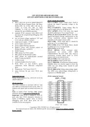
OLIMEX© 2012<strong>OLIMEXINO</strong>-<strong>32U4</strong> User's ManualCHAPTER 9SCHEMATICS9. Introduction to the chapterIn this chapter are located the schematics describing logically and physically <strong>OLIMEXINO</strong>-<strong>32U4</strong>.9.1 Eagle schematic<strong>OLIMEXINO</strong>-<strong>32U4</strong> schematic is visible for reference here. You should zoom the pdf for a betterview and also string search is available. You can also find them on the web page for <strong>OLIMEXINO</strong>-<strong>32U4</strong> at our site: http://www.olimex.com/dev/<strong>OLIMEXINO</strong>-<strong>32U4</strong>.html. They are located inHARDWARE section.Note that <strong>OLIMEXINO</strong>-<strong>32U4</strong> schematic is released under Creative Commons Attribution-ShareAlike 3.0 United States License and the whole project is released underThe EAGLE schematic is situated on the next page for quicker reference.Page 25 of 29
DSGD123DOLIMEX© 2012<strong>OLIMEXINO</strong>-<strong>32U4</strong> User's ManualGND2GND1GND4GND3VBUSD-D+IDGNDUSB-MINIC6 10nFUSBUSBRSTR8330R7-12VDCD2PWR 1N5819(S4SOD-123)YDJ-1136DVCCFB/600 OHM/1206(321611C-601)R74.7kT1107A(6x3.8x2.5mm)C112.2uF/16VL1VINC122.2uF/16VNAAVCCD1100nF10uF/6.3V100nF5V_USBNA[1N5819(S4SOD-123)]C15RESETFET1IRLML6402VR1(5.0V)AMS1117-ADJINADJ/GND R3100R/1%R4330R/1%DVCCC1 C2 C3 C4C7OUTR1R2100nFBUTTONS5V_USBG S10uF/6.3V100nF22R22RBUT330R5.375VC13R10D4DVCC+5VC2310uF/6.3VR94.7kT1107A(6x3.8x2.5mm)1N5819(S4SOD-123)PWR_LEDLED0603(RED)2k20pF20pF#HWB100nF+5V10uF/6.3V5V_USBQ116.000MHz/SMD5x3.2/12pF+5VU2MCP73812T-420I/OT15kopen10uF/6.3VC5<strong>OLIMEXINO</strong>-<strong>32U4</strong> Rev.ADesigned by: WWW.OLIMEX.COM/DEV1uF/10VD- D-D+ D+C8C9R5C16C17GNDGNDBattery Charger42VDD VBAT 3BAT TERYCE 1CHARGERVSS PROG 5R18appr. 70 mA charge currentD7(LED1)CloseLED1LED0603/GREENCHG_D1 2+5VVBATRESETXTAL2XTAL1D3(SCL)D2(SDA)D0(RXD)D1(TXD)D4TXLEDD12D6LED1_EC18R172kR610k1 213244414342675354315233416171819202125222627D31N5819(S4SOD-123)FET2U1IRLML640210uF/6.3V12-3.7V-LI_BATDW02R#RESETAVCCAVCCVCCVCCUVCCUCAPVBUSUGNDGNDGNDGNDGNDD-D+XTAL2XTAL1PD0/OC0B/SCL/INT0PD1/SDA/INT1PD2/RXD1/INT2PD3/TXD1/INT3PD4/ICP1/ADC8PD5/XCK1/CTSPD6/T1/#OC4D/ADC9PD7/T0/OC4D/ADC10ATMEGA<strong>32U4</strong>-AUD9(LED2)Close2kLED2LED0603/YELLOWC22LED2_ER161 2VR2(3.3V)MCP1700T-3302E/MB3.3V/5VHR1x3(3.3V:Open/5V:Close)C20100nF10uF/6.3V2kTXLEDLED0603/GREEN3.3VTXLEDC21AREFPF0/ADC0PF1/ADC1PF4/ADC4/TCKPF5/ADC5/TMSPF6/ADC6/TDOPF7/ADC7/TDIPC7/ICP3/CLK0/OC4APC6/OC3A/#OC4AINT6/AIN0/PE6PE2/#HWBPB0/SS/PCINT0PB1/PCINT1/SCLKPB2/PDI/PCINT2/MOSIPB3/PDO/PCINT3/MISOPB4/PCINT4/ADC11PB5/PCINT5/OC1A/#OC4B/ADC12PB6/PCINT6/OC1B/OC4B/ADC13PB7/PCINT7/OC0A/OC1C/#RTSSTAT LEDSPOWER_SUPPLY+21VINVOUTGND3R1542414039383736323113389101128293012+5VAREF C10100nFA5A4A3A2A1A0D13(UEXT_#CS)D5D7(LED1)#HWBD14(RXLED)D15(SCK)D16(MOSI)D17(MISO)D8(UEXT_PWR_E)D9(LED2)D10D1122uH/10%/5mACLOSEClose2kRXLEDLED0603/YELLOWDVCCD14(RXLED)RXLED_EL2AGND_E1 2R141 2DVCC DVCCAVCCC1410uF/6.3VR22NAR23NA3.3V_E DVCC 3.3V_E3.3V_E 3.3V_E1 2R11_ECloseR114.7kR190 R(Board_Mounted)0RCON1RESET123.3V3+5V456VINNACON2A01A12A23A34A45A56NACON3D0(RXD)1D1(TXD)2D2(SDA)3D3(SCL)4D45D56D67D7(LED1)8NACON4D8(UEXT_PWR_E) 1D9(LED2)2D103D114D125D13(UEXT_#CS) 67AREF8D2(SDA)9D3(SCL)10NAICSPD17(MISO)1 2D15(SCK)3 4 D16(MOSI)RESET5 6NA(HR2x3)FET3R12_EIRLML6402R20Close100kC19R21FET3_E2 1 D8(UEXT_PWR_E)1uF/10V10k CloseR12UEXT4.7k1 2D1(TXD)3 4 D0(RXD)D3(SCL)5 6 D2(SDA)D17(MISO) 7 8 D16(MOSI)D15(SCK) 9 10 D13(UEXT_#CS)G SICSPBH10RUEXTPLATFORM1RST3V35VGNDGNDVINA0A1A2A3A4A5D0D1D2D3D4D5D6D7D8D9D10D11D12D13GNDAREFSDASCL1xPN1x10+1xPN1 x8+2xPN1x6DVCC1 2POWERR13_EClose1 2R134.7kDIGITALANALOGARDUINO LEONARDO PLATFORMDIGITALPage 26 of 29
OLIMEX© 2012<strong>OLIMEXINO</strong>-<strong>32U4</strong> User's Manual9.2 Physical dimensionsNote that all dimensions are in inches.Page 27 of 29
OLIMEX© 2012<strong>OLIMEXINO</strong>-<strong>32U4</strong> User's ManualCHAPTER 10REVISION HISTORY10. Introduction to the chapterIn this chapter you will find the current and the previous version of the document you are reading.Also the web-page for your device is listed. Be sure to check it after a purchase for the latestavailable updates and examples.10.1 Document revisionRevisionChangesModifiedPagesInitial Initial Creation AllBManual adjusted for Arduino IDE version 1.0.1Fixed link8,915Page 28 of 29
OLIMEX© 2012<strong>OLIMEXINO</strong>-<strong>32U4</strong> User's Manual10.2 Web page of your deviceThe web page you can visit for more info on your device ishttp://www.olimex.com/dev/<strong>OLIMEXINO</strong>-<strong>32U4</strong>.html. There you can find more info and someexamples.Web page of the original Arduino and Arduino software: http://arduino.cc/en/.ORDER CODES:<strong>OLIMEXINO</strong>-<strong>32U4</strong> - completely assembled and testedUSB-MINI-CABLE - USBmini to USB-A cableHow to order?You can order to us directly or by any of our distributors.Check our webpage http://www.olimex.com/ for more info.Page 29 of 29