Supplement to the Canopy System Release 8 User Guide PMP 400
Supplement to the Canopy System Release 8 User Guide PMP 400
Supplement to the Canopy System Release 8 User Guide PMP 400

You also want an ePaper? Increase the reach of your titles
YUMPU automatically turns print PDFs into web optimized ePapers that Google loves.
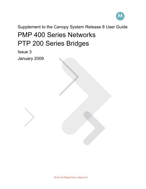
<strong>PMP</strong> <strong>400</strong> and PTP 200 Series<strong>Canopy</strong> <strong>User</strong> <strong>Guide</strong> <strong>Supplement</strong>NoticesSee important safety notice on exposure distance in Section 6.3 on page 40.See important regula<strong>to</strong>ry and legal notices in Section 2 on page 6.Trademarks, Product Names, and Service NamesMOTOROLA, <strong>the</strong> stylized M Logo, <strong>Canopy</strong>, and all o<strong>the</strong>r trademarks indicated as such herein areregistered trademarks of Mo<strong>to</strong>rola, Inc. ® Reg. US Pat & Tm. Office. MOTOwi4 is a trademark ofMo<strong>to</strong>rola, Inc. All o<strong>the</strong>r product or service names are <strong>the</strong> property of <strong>the</strong>ir respective owners.© 2009 Mo<strong>to</strong>rola, Inc. All rights reservedhttp://www.mo<strong>to</strong>rola.com/canopyIssue 3, January 2009 Page 2 of 45
<strong>PMP</strong> <strong>400</strong> and PTP 200 Series<strong>Canopy</strong> <strong>User</strong> <strong>Guide</strong> <strong>Supplement</strong>Table of Contents1 Introduction ............................................................................................................... 42 Product Description .................................................................................................. 63 Planning................................................................................................................... 134 Configuring.............................................................................................................. 175 Installation ............................................................................................................... 296 Regula<strong>to</strong>ry and Legal Notices ............................................................................... 36List of TablesTable 1: Products and Model Numbers ........................................................................... 6Table 2: Performance Details........................................................................................ 12Table 3: 5.4 GHz Channel Center Frequencies, by Region ........................................... 13Table 4: 4.9 GHz Channel Center Frequencies............................................................. 13Table 5: Control Slot Settings........................................................................................ 20Table 6: <strong>Release</strong> 8.4 Operation based on Region Code ............................................... 21Table 7: US FCC IDs and Industry Canada Certification Numbers and CoveredConfigurations ........................................................................................................ 37Table 8: Disclosure Table ............................................................................................. 40Table 9: Exposure Separation Distances ...................................................................... 40Table 10: Calculated Exposure Distances and Power Compliance Margins.................. 41List of FiguresFigure 1: Radio (with or without integrated antenna) 7Figure 2: <strong>PMP</strong> 54<strong>400</strong> AP with connec<strong>to</strong>rized radio and antenna 7Figure 3: <strong>PMP</strong> 49<strong>400</strong> AP with connec<strong>to</strong>rized radio and antenna 8Figure 4: LOS, nLOS, and NLOS 9Figure 5: Dynamic Rate Adapt on AP "Configuration => General" page 18Figure 6: Region Code on AP “Configuration => General” page 24Figure 7: Configured Region Code on SM Configuration => General page 25Figure 8: Active Region Code on SM Home => General Status page 25Figure 9: Ground lug highlighted on AP 34Issue 3, January 2009 Page 3 of 45
<strong>PMP</strong> <strong>400</strong> and PTP 200 Series<strong>Canopy</strong> <strong>User</strong> <strong>Guide</strong> <strong>Supplement</strong>1 IntroductionThis guide provides product description, planning, configuration, and installation informationspecific <strong>to</strong> <strong>the</strong> <strong>PMP</strong> <strong>400</strong> Series networks and PTP 200 Series bridges. It should be used alongwith <strong>the</strong> <strong>Canopy</strong> <strong>System</strong> <strong>Release</strong> 8 <strong>User</strong> <strong>Guide</strong>, which covers general information, including allnetwork features, RF control features, and GUI (Graphical <strong>User</strong> Interface) features commonacross <strong>PMP</strong> 100, 200 and <strong>400</strong> Series networks and PTP 100 and 200 Series bridges. The<strong>Canopy</strong> <strong>System</strong> <strong>Release</strong> 8 <strong>User</strong> <strong>Guide</strong> is available from <strong>the</strong> “<strong>User</strong> <strong>Guide</strong>s” section of <strong>the</strong> <strong>Canopy</strong>Document Library, http://mo<strong>to</strong>rola.canopywireless.com/support/library/?region=1&cat=8.This guide assumes that <strong>the</strong> reader has general RF (Radio Frequency) and Internet Pro<strong>to</strong>col (IP)knowledge and background.This issue, Issue 2, is consistent with features provided by <strong>Canopy</strong> <strong>Release</strong> 8.4.3. Separate<strong>Release</strong> Notes for <strong>Canopy</strong> Software <strong>Release</strong> 8.4.3 are available and include open issues ando<strong>the</strong>r notes.1.1 ABBREVIATIONSThe following abbreviations may be used in <strong>the</strong>se notes:1X2X3XAPBHBHMBHSCMMCNUTDFSEIRPETSIFSKMIBOFDMPtPPtMPQAMQPSKRFSM1X operation, with typical max aggregate (up and down)throughput of 7 Mbps (2 Mbps for 900 MHz)2X operation, with typical max aggregate (up and down)throughput of 14 Mbps (4 Mbps for 900 MHz)3X operation, with typical max aggregate (up and down)throughput of over 20 MbpsAccess Point ModuleBackhaul Module, ei<strong>the</strong>r timing master or timing slaveBackhaul Module – timing masterBackhaul Module – timing slaveCluster Management Module<strong>Canopy</strong> Network Updater ToolDynamic Frequency Selection for radar avoidanceEquivalent Isotropically Radiated PowerEuropean Telecommunications Standards InstituteFrequency Shift KeyingManagement Information Base for SNMPOrthogonal Frequency Division MultiplexingPoint-<strong>to</strong>-Point (Backhauls)Point-<strong>to</strong>-Multi-Point (AP <strong>to</strong> SMs)Quadrature Amplitude ModulationQuadrature Phase Shift KeyingRadio FrequencySubscriber Module1.2 DOCUMENT CHANGE HISTORYIssue 1First IssueIssue 2Significant changes for:Issue 3, January 2009 Page 4 of 45
<strong>PMP</strong> <strong>400</strong> and PTP 200 Series<strong>Canopy</strong> <strong>User</strong> <strong>Guide</strong> <strong>Supplement</strong>2 Product Description<strong>PMP</strong> <strong>400</strong> Series networks and PTP 200 Series bridges add OFDM-based (Orthogonal FrequencyDivision Multiplexing) products <strong>to</strong> <strong>the</strong> <strong>Canopy</strong> family.• SMs are available with ei<strong>the</strong>r an integrated antenna or an external N-type connec<strong>to</strong>ron a short length of coaxial cable for connecting <strong>to</strong> a connec<strong>to</strong>rized antenna.• APs are always connec<strong>to</strong>rized, and sold ei<strong>the</strong>r with a connec<strong>to</strong>rized antenna as a kit,or with no antenna.• BHs are available with ei<strong>the</strong>r an integrated antenna or an external N-type connec<strong>to</strong>ron a short length of coaxial cable for connecting <strong>to</strong> a connec<strong>to</strong>rized antenna.<strong>PMP</strong> <strong>400</strong> Series networks are available in multiple bands:• <strong>PMP</strong> 54<strong>400</strong> APs and SMs provide connectivity in <strong>the</strong> unlicensed 5.4 GHz band.• <strong>PMP</strong> 49<strong>400</strong> APs and SMs provide connectivity in <strong>the</strong> licensed 4.9 GHz bandallocated <strong>to</strong> public safety services. State and local governmental entities are eligible<strong>to</strong> hold 4.9 GHz licenses.Table 1 shows <strong>the</strong> Mo<strong>to</strong>rola <strong>PMP</strong> <strong>400</strong> Series and PTP 200 Series products available.Table 1: Products and Model NumbersModelNumberNameModuleDESorAESAntenna TypeAntennaincluded?PictureSpecs5440SM <strong>PMP</strong> 54<strong>400</strong> 5.4 GHz OFDM SM DES Integrated Yes Figure 1 2.7.25441SM <strong>PMP</strong> 54<strong>400</strong> 5.4 GHz OFDM SM AES Integrated Yes Figure 1 2.7.25440SMC <strong>PMP</strong> 54<strong>400</strong> 5.4 GHz OFDM SM DES Connec<strong>to</strong>rized No Figure 1 2.7.35441SMC <strong>PMP</strong> 54<strong>400</strong> 5.4 GHz OFDM SM AES Connec<strong>to</strong>rized No Figure 1 2.7.35440AP <strong>PMP</strong> 54<strong>400</strong> 5.4 GHz OFDM AP DES Connec<strong>to</strong>rized Yes Figure 2 2.7.45441AP <strong>PMP</strong> 54<strong>400</strong> 5.4 GHz OFDM AP AES Connec<strong>to</strong>rized Yes Figure 2 2.7.45440APC <strong>PMP</strong> 54<strong>400</strong> 5.4 GHz OFDM AP DES Connec<strong>to</strong>rized No Figure 1 2.7.35441APC <strong>PMP</strong> 54<strong>400</strong> 5.4 GHz OFDM AP AES Connec<strong>to</strong>rized No Figure 1 2.7.35440BH PTP 54200 5.4 GHz OFDM BH DES Integrated Yes Figure 1 2.7.25441BH PTP 54200 5.4 GHz OFDM BH AES Integrated Yes Figure 1 2.7.25440BHC PTP 54200 5.4 GHz OFDM BH DES Connec<strong>to</strong>rized No Figure 1 2.7.35441BHC PTP 54200 5.4 GHz OFDM BH AES Connec<strong>to</strong>rized No Figure 1 2.7.34940SM <strong>PMP</strong> 49<strong>400</strong> 4.9 GHz OFDM SM DES Integrated Yes Figure 1 2.7.24941SM <strong>PMP</strong> 49<strong>400</strong> 4.9 GHz OFDM SM AES Integrated Yes Figure 1 2.7.24940SMC <strong>PMP</strong> 49<strong>400</strong> 4.9 GHz OFDM SM DES Connec<strong>to</strong>rized No Figure 1 2.7.34941SMC <strong>PMP</strong> 49<strong>400</strong> 4.9 GHz OFDM SM AES Connec<strong>to</strong>rized No Figure 1 2.7.34940AP <strong>PMP</strong> 49<strong>400</strong> 4.9 GHz OFDM AP DES Connec<strong>to</strong>rized Yes Figure 3 2.7.44941AP <strong>PMP</strong> 49<strong>400</strong> 4.9 GHz OFDM AP AES Connec<strong>to</strong>rized Yes Figure 3 2.7.44940APC <strong>PMP</strong> 49<strong>400</strong> 4.9 GHz OFDM AP DES Connec<strong>to</strong>rized No Figure 1 2.7.3Issue 3, January 2009 Page 6 of 45
<strong>PMP</strong> <strong>400</strong> and PTP 200 Series<strong>Canopy</strong> <strong>User</strong> <strong>Guide</strong> <strong>Supplement</strong>ModelNumberNameModuleDESorAESAntenna TypeAntennaincluded?PictureSpecs4941APC <strong>PMP</strong> 49<strong>400</strong> 4.9 GHz OFDM AP AES Connec<strong>to</strong>rized No Figure 1 2.7.3Figure 1: Radio (with or without integrated antenna)Figure 2: <strong>PMP</strong> 54<strong>400</strong> AP with connec<strong>to</strong>rized radio and antennaIssue 3, January 2009 Page 7 of 45
<strong>PMP</strong> <strong>400</strong> and PTP 200 Series<strong>Canopy</strong> <strong>User</strong> <strong>Guide</strong> <strong>Supplement</strong>Figure 3: <strong>PMP</strong> 49<strong>400</strong> AP with connec<strong>to</strong>rized radio and antennaA <strong>Canopy</strong> CMMmicro or CMM4 provides synchronization and power <strong>to</strong> <strong>the</strong> <strong>PMP</strong> <strong>400</strong> Series APsand PTP 200 Series BHMs. A 600SSC surge suppressor, a successor <strong>to</strong> <strong>the</strong> 300SS and 600SSBsurge suppressors, provides over-voltage and over-current protection <strong>to</strong> APs, SMs, and BHs invarious configurations.2.1 TECHNOLOGY AND BENEFITSThese radios au<strong>to</strong>matically select QPSK (Quadrature Phase Shift Keying), 16-QAM (QuadratureAmplitude Modulation), or 64-QAM based on RF environment <strong>to</strong> provide 1X, 2X, and 3Xoperation, respectively. This provides 3 speeds and a throughput of over 20 Mbps aggregate(sum of up plus down) compared <strong>to</strong> FSK <strong>Canopy</strong> products with 2 speeds and a throughput of up<strong>to</strong> 14 Mbps.The OFDM radios feature lower receive sensitivity, FEC (Forward Error Correction), and higherantenna gain, all of which combine <strong>to</strong> provide longer range within regula<strong>to</strong>ry-specified EIRP(Equivalent Isotropic Radiated Power).Details on performance are listed in Table 2 on page 12.The <strong>PMP</strong> <strong>400</strong> and PTP 200 Series radios use an OFDM physical layer with 10 MHz channels and256 sub-carriers. Due <strong>to</strong> <strong>the</strong> different carrier and modulation schemes between <strong>the</strong>se OFDMradios and FSK <strong>Canopy</strong> radios, <strong>the</strong> two do not interoperate over <strong>the</strong> air. For example, an OFDMSM cannot connect <strong>to</strong> an FSK AP.Issue 3, January 2009 Page 8 of 45
<strong>PMP</strong> <strong>400</strong> and PTP 200 Series<strong>Canopy</strong> <strong>User</strong> <strong>Guide</strong> <strong>Supplement</strong>2.1.1 NLOS and nLOS Benefits and LimitationsThe use of OFDM technology will help in many cases of NLOS (Non Line-of-Sight) and nLOSnear Line-of-Sight (nLOS) links. LOS (Line-of-Sight ) means <strong>the</strong> installer can see <strong>the</strong> AP from <strong>the</strong>SM and <strong>the</strong> first Fresnel zone is clear. An example of nLOS is when <strong>the</strong> installer can see <strong>the</strong> APfrom <strong>the</strong> SM, but a portion of <strong>the</strong> first Fresnel is blocked. An example of NLOS is when <strong>the</strong>installer cannot see <strong>the</strong> AP from <strong>the</strong> SM, and a portion or even much of <strong>the</strong> first Fresnel isblocked, but subsequent Fresnel zones are open. Figure 4 shows examples of such links.Figure 4: LOS, nLOS, and NLOSWhereas multi-pathing degrades a link in some technologies, like FSK, OFDM can often usemulti-pathing <strong>to</strong> advantage <strong>to</strong> overcome nLOS and NLOS, especially in cases where <strong>the</strong> Fresnelzone is only partially blocked by buildings, “urban canyons”, or foliage. OFDM tends <strong>to</strong> helpespecially when obstacles are near <strong>the</strong> middle of <strong>the</strong> link, and less so when <strong>the</strong> obstacles arevery near <strong>the</strong> SM, AP, or BH.However, attenuation through walls and trees is substantial for any use of <strong>the</strong> 5.4 GHz or 4.9 GHzfrequency bands. Even with OFDM, <strong>the</strong>se products should not be expected <strong>to</strong> penetrate walls orextensive trees and foliage.2.2 APPLICATIONSApplications for <strong>the</strong> <strong>PMP</strong> 54<strong>400</strong> and PTP 54200 Series systems include• High throughput enterprise applications• NLOS/nLOS video surveillance in metro areas• Extend networks in<strong>to</strong> urban areas• Extend networks in<strong>to</strong> areas with foliageApplications for <strong>the</strong> <strong>PMP</strong> 49<strong>400</strong> Series systems include• High throughput licensed network for government applications• Municipal network - NLOS/nLOS video surveillance in metro areas• Disaster relief network• Data service network - extend licensed networks in<strong>to</strong> areas with foliageIssue 3, January 2009 Page 9 of 45
<strong>PMP</strong> <strong>400</strong> and PTP 200 Series<strong>Canopy</strong> <strong>User</strong> <strong>Guide</strong> <strong>Supplement</strong>2.3 CONFIGURATION OPTIONS – RF, IP, DFSThese systems use <strong>the</strong> <strong>Canopy</strong> Media Access Controller (MAC) layer. Settings like DownlinkData %, Range, and Control Slots are similar <strong>to</strong> <strong>Canopy</strong> FSK radios. An AP can communicate <strong>to</strong>over 200 SMs, similar <strong>to</strong> a <strong>Canopy</strong> FSK AP.The GUI (Graphical <strong>User</strong> Interface) is almost identical <strong>to</strong> <strong>Canopy</strong>’s, with a few additions <strong>to</strong>support OFDM-specific features.Network features like High Priority using DiffServ, MIR, CIR, NAT, DHCP and VLAN are availablefor <strong>the</strong> <strong>PMP</strong> <strong>400</strong> and PTP 200 Series OFDM radios, and are configured in <strong>the</strong> same way as <strong>the</strong>yare for <strong>the</strong> <strong>PMP</strong> 100 and 200 Series and PTP 100 Series radios.In <strong>the</strong> 5.4 GHz band, DFS (Dynamic Frequency Selection) is provided for regula<strong>to</strong>ry complian<strong>to</strong>peration, and is activated using <strong>the</strong> “Region Code” feature. Two alternate frequencies can beconfigured <strong>to</strong> provide service in <strong>the</strong> unlikely case a module detects radar and triggers DFS, <strong>the</strong>same as standard <strong>Canopy</strong>. “External Antenna Gain” may need <strong>to</strong> be configured consistent withany antennas used, <strong>to</strong> avoid making <strong>the</strong> system overly sensitive <strong>to</strong> radar detection. “Whitening,” atechnique used <strong>to</strong> avoid self-interference on <strong>Canopy</strong> FSK radios is not offered as an option on <strong>the</strong><strong>PMP</strong> <strong>400</strong> and PTP 200 Series radios, as whitening is not a technology applicable <strong>to</strong> an OFDMsignal.2.4 RELEASE MAPPING TO PRODUCTS<strong>Release</strong>s run on <strong>the</strong> various products as follows:• <strong>Release</strong> 9.0 or <strong>Release</strong> 8.2.x runs on <strong>Canopy</strong> FSK radios (<strong>PMP</strong> 100 and 200 andPTP 100 Series radios).• <strong>Release</strong> 8.4.x runs on <strong>PMP</strong> 54<strong>400</strong> and PTP 54200 Series OFDM radios.• “<strong>Release</strong> 8.3” is not planned <strong>to</strong> be used for release numbering.• <strong>Release</strong> 9.3.1 runs on <strong>PMP</strong> 49<strong>400</strong> Series OFDM radios2.5 POWER AND GROUNDINGThe <strong>PMP</strong> <strong>400</strong> and PTP 200 Series radios use a 30 VDC nominal power system, instead of <strong>the</strong> 24VDC nominal power system used previously in standard <strong>Canopy</strong>. A new 30 VDC power supply isavailable for <strong>the</strong> CMMmicro, and a new 30 VDC nominal (specified and labeled as 29.5 VDC)power supply is available for <strong>the</strong> SM.The new 30 VDC power supplies can also be used for standard <strong>Canopy</strong>, and are replacing <strong>the</strong> 24VDC power supplies in <strong>the</strong> <strong>Canopy</strong> product line.The <strong>PMP</strong> <strong>400</strong> and PTP 200 Series radios have slightly higher power use than <strong>Canopy</strong> FSKradios, and <strong>the</strong> higher voltage is needed <strong>to</strong> carry <strong>the</strong> higher wattage on cable runs approaching<strong>the</strong> 100 meter (328 ft) maximum length. CMMmicro 24 VDC power supplies and <strong>the</strong> latest versionof SM 24 VDC power supplies can power <strong>PMP</strong> <strong>400</strong> and PTP 200 Series radios for shorter runs.Earlier versions of SM 24 VDC power supplies, especially <strong>the</strong> earlier heavier transformers,cannot. The best practice is <strong>to</strong> use 30 VDC power supplies with <strong>PMP</strong> <strong>400</strong> and PTP 200 Seriesradios, and avoid potential issues and cable-length-specific engineering.Due <strong>to</strong> <strong>the</strong> full metallic connection <strong>to</strong> <strong>the</strong> <strong>to</strong>wer or support structure through <strong>the</strong> AP’s antenna or aconnec<strong>to</strong>rized BH’s antenna, grounding of <strong>the</strong> AP or BH and a 600SSC surge suppressor within 3ft (1 m) of <strong>the</strong> AP or BH is strongly recommended <strong>to</strong> suppress overvoltages and overcurrents,such as those caused by near-miss lightning. APs and BHs provide a grounding lug for grounding<strong>to</strong> <strong>the</strong> <strong>to</strong>wer or support structure. A pole mount kit is available for <strong>the</strong> 600SSC, and provides agrounding lug that can be used for terminating grounding straps from both <strong>the</strong> 600SSC and <strong>the</strong>AP.Issue 3, January 2009 Page 10 of 45
<strong>PMP</strong> <strong>400</strong> and PTP 200 Series<strong>Canopy</strong> <strong>User</strong> <strong>Guide</strong> <strong>Supplement</strong>2.6 ADMINISTRATION SYSTEMSStandard <strong>Canopy</strong> administration systems are used <strong>to</strong> support <strong>the</strong> <strong>PMP</strong> <strong>400</strong> and PTP 200 Seriesproducts, with <strong>the</strong> only requirement being that <strong>the</strong> administration systems must be at <strong>the</strong>appropriate release level:• Prizm 3.1 is <strong>the</strong> element management system for <strong>PMP</strong> <strong>400</strong> and PTP 200 Seriesproducts. In addition <strong>to</strong> managing and moni<strong>to</strong>ring <strong>Canopy</strong> modules, Prizm 3.1 can beused <strong>to</strong> update <strong>the</strong>m.• CNUT 3.1 (<strong>Canopy</strong> Network Update Tool) is <strong>the</strong> stand-alone update <strong>to</strong>ol for <strong>PMP</strong> <strong>400</strong>and PTP 200 Series products for opera<strong>to</strong>rs not using Prizm.2.7 TECHNICAL DETAILS, SPECIFICATIONS, PERFORMANCE<strong>PMP</strong> <strong>400</strong> and PTP 200 systems consist of radios and antennas available in variouscombinations. The following sections list technical details for <strong>the</strong> radio and for each form fac<strong>to</strong>r.2.7.1 Radio specifications (common <strong>to</strong> all form fac<strong>to</strong>rs)• APs and BHs have settable Transmit Output Power.• SMs have Au<strong>to</strong> TPC (Transmit Power Control), set by <strong>the</strong> AP <strong>to</strong> provide powerleveling for close-in SMs• 5.4 GHz radios have a range of -30 <strong>to</strong> 10 dBm, and a default of 10 dBm.• 4.9 GHz radios have a range of -30 <strong>to</strong> 18 dBm, and a default of 18 dBm.• 12.5 W DC power2.7.2 Radio with integrated antenna – form fac<strong>to</strong>r specifications• Radio with an integrated, internal antenna• 18° x 18° 3 dB beam• 17 dBi gain for antenna at 5.4 GHz. 17 dBi antenna gain plus 10 dBm transmit powergives <strong>the</strong> regula<strong>to</strong>ry maximum 27 dBm EIRP.• 16 dBi gain for antenna at 4.9 GHz. 16 dBi antenna gain plus 18 dBm transmit powergives 34 dBm EIRP.• 2.8 lb, 13.25 x 8.25 x 3.75 in (hwd) (~1.3 kg, 34 x 21 x 9.5 cm)2.7.3 Connec<strong>to</strong>rized radio – form fac<strong>to</strong>r specifications• Connec<strong>to</strong>rized radio only (antenna <strong>to</strong> be provided by opera<strong>to</strong>r) – N-type connec<strong>to</strong>r• 2.8 lb, 13.25 x 8.25 x 3.75 in (hwd) (~1.3 kg, 34 x 21 x 9.5 cm)2.7.4 Kitted connec<strong>to</strong>rized radio specifications (antenna included) – form fac<strong>to</strong>rspecifications• Connec<strong>to</strong>rized radio and connec<strong>to</strong>rized antenna kitted <strong>to</strong>ge<strong>the</strong>r – N-type connec<strong>to</strong>r• 90° sec<strong>to</strong>rs• Antenna optimized for system coverage vs system self-interference for 90° sec<strong>to</strong>rs (3dB beam pattern of 60° azimuth by 5° elevation, with near-in null fill)• 18 dBi gain for antenna at 5.4 GHz. 18 dBi antenna gain minus 1 dB cable loss plus10 dBm transmit power gives <strong>the</strong> regula<strong>to</strong>ry max 27 dBm EIRP.• 17 dBi gain for antenna at 4.9 GHz. 17 dBi antenna gain minus 1 dB cable loss plus18 dBm transmit power gives 34 dBm EIRP.• 13 lb, 28 x 8.25 x 11 in (hwd) (~6 kg, 71 x 21 x 28 cm)Issue 3, January 2009 Page 11 of 45
<strong>PMP</strong> <strong>400</strong> and PTP 200 Series<strong>Canopy</strong> <strong>User</strong> <strong>Guide</strong> <strong>Supplement</strong>2.7.5 <strong>System</strong> technical details• Standard <strong>Canopy</strong> temperature range of -40° C <strong>to</strong> +55° C• Latency of 5-7 msec roundtrip• Products available with ei<strong>the</strong>r DES or AES encryptionTable 2 shows performance details for <strong>the</strong> <strong>PMP</strong> 54<strong>400</strong>, PTP 54200, and <strong>PMP</strong> 49<strong>400</strong> systems,with <strong>the</strong> standard <strong>Canopy</strong> <strong>PMP</strong> 54200 5.4 GHz FSK details shown for comparison.Table 2: Performance DetailsProductChannelWidthParametersPerformance Details1X 2X 3X<strong>PMP</strong> 54<strong>400</strong>andPTP 54200(5.4 GHz OFDM)<strong>PMP</strong> 49<strong>400</strong>(4.9 GHz OFDM)10 MHz10 MHzModulation QPSK 16 QAM 64 QAMTypical Maximum Range 5 mi/8 km 2.5 mi/4 km 1.25 mi/2 kmTypical Maximum Aggregate(up+down) ThroughputNominal Receive Sensitivity(including FEC)7 Mbps 14 Mbps 21 Mbps-89 dBm -78 dBm -70 dBmModulation QPSK 16 QAM 64 QAMTypical Maximum Range 15 mi/24 km 4 mi/6.5 km 1.7 mi/2.7 kmTypical Maximum Aggregate(up+down) Throughput7 Mbps 14 Mbps 21 MbpsNominal Receive Sensitivity(including FEC)-89 dBm -78 dBm -70 dBm<strong>PMP</strong> 54200(5.4 GHz FSK)(for comparison).20 MHzModulation 2-level FSK 4-level FSK noneTypical Maximum Range 2 mi/3.2 km 1 mi/1.6 km noneTypical Maximum Aggregate(up+down) Throughput7 Mbps 14 Mbps noneNominal Receive Sensitivity -86 dBm -70 dBm noneIssue 3, January 2009 Page 12 of 45
<strong>PMP</strong> <strong>400</strong> and PTP 200 Series<strong>Canopy</strong> <strong>User</strong> <strong>Guide</strong> <strong>Supplement</strong>3 Planning<strong>PMP</strong> <strong>400</strong> and PTP 200 Series systems use a 10 MHz channel size configurable on 5 MHzcenters. This channel size, along with some different characteristics due <strong>to</strong> <strong>the</strong> use OFDM carriertechnology and QPSK, 16 QAM, or 64 QAM modulation, supports somewhat different channelplanning than for standard <strong>Canopy</strong>. (For reference, <strong>PMP</strong> 100/200 Series uses 20 MHz channelsconfigurable on 5 MHz centers, single carrier technology, and 2-level and 4-level FSKmodulation.)3.1 TOWER CHANNEL PLANNINGFor a single cluster of 4 APs on a <strong>to</strong>wer, 2-channel re-use with channels on 10 MHz channelcenter spacing gives good performance. In channel design parlance, this can be stated as ABABchannel planning, with no guard band needed between A and B. A typical arrangement might be<strong>to</strong> use radios configured for 5480 MHz aimed north and south, and radios configured for 5490MHz aimed east and west.(For reference, standard <strong>Canopy</strong> uses 2-channel re-use with clusters of 6 APs on a <strong>to</strong>wer withchannel center spacing of ei<strong>the</strong>r 25 MHz for Advantage APs or 20 MHz for non-Advantage APs.This is ABCABC channel planning, with 5 MHz guard band between <strong>the</strong> 20 MHz channels forAdvantage APs and no guard band needed for non-Advantage.)Available 5.4 GHz channel center frequencies for each region are shown in Table 3. These varyby region due <strong>to</strong>• different band edge RF specifications (for example, between Canada/US andEurope)• requirements in Europe and Canada <strong>to</strong> not impinge on <strong>the</strong> frequencies between 5600and 5650 MHz, which are frequencies on which some wea<strong>the</strong>r radar operateTable 3: 5.4 GHz Channel Center Frequencies, by RegionRegionRange of Center FrequenciesAvailable (MHz)(on 5 MHz centers within thisrange, inclusive)Maximum number ofnon-overlappingchannelsUS 5480 - 5710 24Canada 5480 – 5595, 5655 - 5710 18Europe 5475 - 5595, 5655 - 5715 20US FSK (for comparison) 5495 - 5705 11Canada FSK (forcomparison)5495 - 5575, 5675 - 57057Available 4.9 GHz channel center frequencies are shown in Table 4.Table 4: 4.9 GHz Channel Center FrequenciesRange of Center FrequenciesAvailable (MHz)(on 5 MHz centers within thisrange, inclusive)Maximum number ofnon-overlappingchannels4945 - 4985 5Issue 3, January 2009 Page 13 of 45
<strong>PMP</strong> <strong>400</strong> and PTP 200 Series<strong>Canopy</strong> <strong>User</strong> <strong>Guide</strong> <strong>Supplement</strong>The best practice for channel planning for APs is <strong>to</strong> conduct extensive site RF surveys beforechoosing channels. For those with <strong>the</strong> equipment and expertise, use commercial and industrialspectrum analysis equipment. The <strong>PMP</strong> <strong>400</strong> and PTP 200 Series APs and SMs do not provide aspectrum analyzer in <strong>the</strong> first release (planned for a subsequent release), but standard 5.4 GHzFSK SMs can be used <strong>to</strong> give useful information on <strong>the</strong> RF environment in <strong>the</strong> planned <strong>PMP</strong> <strong>400</strong>and PTP 200 Series AP deployment location.3.2 DOWNTILTThe standard AP antenna produces a 3 db beam elevation (up and down) of 5°, with near-in nullfill that allows good coverage of close-in SMs that o<strong>the</strong>rwise would be affected by <strong>the</strong> narrowpattern. This is a narrower pattern than opera<strong>to</strong>rs may be used <strong>to</strong> with standard <strong>Canopy</strong>’s 60° 3dB beam, and may require downtilt on <strong>the</strong> antenna. The standard antenna has provision formeasured downtilt. The opera<strong>to</strong>r should estimate downtilt based on antenna height above <strong>the</strong>service area and using one of <strong>the</strong> many radio analysis and mapping <strong>to</strong>ols or on-line calculation<strong>to</strong>ols for calculating downtilt.3.3 WEATHER RADARSpectrum between 5600 and 5650 MHz (sometimes called <strong>the</strong> “wea<strong>the</strong>r notch”) is used by somewea<strong>the</strong>r radar and is not allowed for use by regulations in some regions, including Canada and,for new equipment, Europe. When <strong>the</strong> <strong>Canopy</strong> module is set <strong>to</strong> one of those regions (configuredon <strong>the</strong> “Configuration => General” page of <strong>the</strong> module), it will not allow configuration of <strong>the</strong>appropriate frequencies, as shown in Table 3. Even in regions where use of <strong>the</strong> spectrumbetween 5600 and 5650 MHz is allowed, such as <strong>the</strong> US, <strong>the</strong> best practice is <strong>to</strong> not use <strong>the</strong>sechannels if <strong>the</strong>re are any o<strong>the</strong>r usable channels available. Only use <strong>the</strong> channels in this “wea<strong>the</strong>rnotch” after performing long-term site surveys (minimum of a week) <strong>to</strong> ascertain <strong>the</strong> spectrum isclear and that <strong>the</strong>re don’t appear <strong>to</strong> be any wea<strong>the</strong>r radar in <strong>the</strong> area that will cause interference<strong>to</strong> your <strong>Canopy</strong> system.3.4 RANGE AND THROUGHPUT PLANNING<strong>PMP</strong> <strong>400</strong> and PTP 200 Series modules provide up <strong>to</strong> 21 Mbps aggregate throughput at distancesof 1.25 mi (~1 km) (1.7 mi for 4.9 GHz systems) in RF environments with clear line-of-sight andlow background interference levels. Additional performance details are shown in Table 2 on page12. RF environments with occluded Fresnel zones or higher background interference levels maygive lower, but still very good, performance, depending on <strong>the</strong> specifics of <strong>the</strong> environment.Similar <strong>to</strong> standard <strong>Canopy</strong>, at any given instant, any radios operating at 1X or 2X take more “airtime” <strong>to</strong> transmit a given amount of data than if <strong>the</strong>y were running at 3X. Similar <strong>to</strong> standard<strong>Canopy</strong>, <strong>PMP</strong> <strong>400</strong> and PTP 200 Series modules may see reduced <strong>to</strong>tal throughput whenhandling traffic with a high percentage of small packets.The effect of this, again similar <strong>to</strong> standard <strong>Canopy</strong>, is that at any given instant <strong>to</strong>tal throughputdepends on• Mix of links running at 3X, 2X, and 1X• Mix of packet sizes3.5 SPECTRUM ANALYZERA spectrum analyzer is available on <strong>the</strong> SM at Tools => Spectrum Analyzer. The spectrumanalyzer is also available on an AP by temporarily converting it <strong>to</strong> an SM by setting <strong>the</strong> DeviceType <strong>to</strong> SM on <strong>the</strong> AP’s Configuration => General page. The spectrum analyzer works like <strong>the</strong>spectrum analyzer in classic FSK SMs.Spectrum analyzer uses includeIssue 3, January 2009 Page 14 of 45
<strong>PMP</strong> <strong>400</strong> and PTP 200 Series<strong>Canopy</strong> <strong>User</strong> <strong>Guide</strong> <strong>Supplement</strong>• Showing relative power levels across <strong>the</strong> band, <strong>to</strong> aid in selecting channels andperforming RF planning.• Troubleshooting <strong>to</strong> finding <strong>the</strong> frequency, relative power level, and location ofinterferers by rotating a single SM, or triangulating from multiple SMs in ageographical area.The OFDM spectrum analyzer, <strong>the</strong> FSK spectrum analyzer, and <strong>the</strong> FSK Receive Power Levelare all measuring and displaying peak power levels. The OFDM Receive Power Level ismeasuring and displaying <strong>the</strong> average power level. In addition, an OFDM SM measures poweracross 10-MHz channels while an FSK SM measures power across 20-MHz channels.Due <strong>to</strong> all this, <strong>the</strong> reported Receive Power Level on an OFDM SM can be 10 <strong>to</strong> 15 dB lowerthan <strong>the</strong> value shown for that channel on <strong>the</strong> spectrum analyzer. For example, for an OFDM APtransmitting on 5540 MHz, <strong>the</strong> OFDM SM might show a Receive Power Level of -70 dBm while<strong>the</strong> OFDM and FSK spectrum analyzers show power levels of -54 and -51 dBm at 5540 MHz.The built-in spectrum analyzer can be very useful as a <strong>to</strong>ol for troubleshooting and RF planning,but doesn’t duplicate <strong>the</strong> accuracy and programmability of a dedicated, high-end spectrumanalyzer, which may be needed in some cases.3.6 COLLOCATION OF 5.4 GHZ OFDM WITH STANDARD 5.4 GHZCANOPY FSKWhen locating 5.4 GHz <strong>PMP</strong> <strong>400</strong> and PTP 200 Series OFDM APs near 5.4 GHz standard<strong>Canopy</strong> FSK APs (especially on <strong>the</strong> same <strong>to</strong>wer, but also in <strong>the</strong> same geographical area), <strong>the</strong>following practices should be followed <strong>to</strong> avoid interference between <strong>the</strong> two systems:• Plan spacing between OFDM and FSK channels <strong>to</strong> provide 25 MHz center spacing,which gives a 10 MHz guard band between <strong>the</strong> 10 MHz OFDM channel and <strong>the</strong> 20MHz FSK channel.• Coordinate Downlink Data %, Range, and Control Slot settings using both <strong>the</strong>OFDM and <strong>the</strong> FSK frame calcula<strong>to</strong>rsThe following paragraphs give more details on <strong>the</strong>se recommended practices.3.6.1 Channel SpacingCenter spacing of 25 MHz between collocated FSK and OFDM APs provides a 10 MHz guardband between <strong>the</strong> 20 MHz and 10 MHz channels, which has proven useful and needed in fieldtesting. Alternatively, in cases where channel planning is severely restricted and <strong>the</strong> 10 MHzguard band (25 MHz spacing) is not possible, using vertical separation of 5 feet or more between<strong>the</strong> OFDM and FSK APs may allow collocation with no guard band (15 MHz spacing) in somedeployments.3.6.2 Frame Calculations and Configuration SettingsInterference between collocated <strong>Canopy</strong> systems can be avoided by following two practices:1. Use a CMM. This synchronizes frame start, so that all collocated APs begintransmitting at <strong>the</strong> same time each 2.5 millisecond frame.2. Use <strong>the</strong> frame calcula<strong>to</strong>rs in each module, OFDM and FSK (<strong>the</strong> frame calcula<strong>to</strong>rs aredifferent, as frame details are different) <strong>to</strong> select Downlink Data %, Range, andControl Slots for each system that produce “Rec SEQ Start” values that are within300 bit times. This ensures that all collocated APs end transmission each framebefore any collocated AP begins <strong>to</strong> receive.Issue 3, January 2009 Page 15 of 45
<strong>PMP</strong> <strong>400</strong> and PTP 200 Series<strong>Canopy</strong> <strong>User</strong> <strong>Guide</strong> <strong>Supplement</strong>When collocating only <strong>Canopy</strong> OFDM APs <strong>to</strong>ge<strong>the</strong>r, or collocating only <strong>Canopy</strong> hardwarescheduledFSK APs <strong>to</strong>ge<strong>the</strong>r, <strong>the</strong> simple practice of setting <strong>the</strong> Downlink Data %, Range, andControl Slots <strong>the</strong> same on all APs ensures <strong>the</strong>y won’t interfere with each o<strong>the</strong>r. (Theseparameters are set on <strong>the</strong> “Configuration => Radio” page of <strong>the</strong> AP.) However, due <strong>to</strong> <strong>the</strong>different “physical” layer between <strong>Canopy</strong> OFDM and <strong>Canopy</strong> FSK, this doesn’t necessarily workwhen collocating OFDM and FSK <strong>to</strong>ge<strong>the</strong>r.You will need <strong>to</strong> use frame calcula<strong>to</strong>rs on both <strong>the</strong> OFDM and FSK modules, as <strong>the</strong>y are differentframe calcula<strong>to</strong>rs. For <strong>the</strong> same Downlink Data %, Range, and Control Slots, <strong>the</strong> framecalcula<strong>to</strong>rs give different results. Use of <strong>the</strong> frame calcula<strong>to</strong>rs is similar <strong>to</strong> <strong>the</strong> previous use whencollocating software-scheduled and hardware-scheduled APs.Procedure 1: Finding collocation values using Frame Calcula<strong>to</strong>rs1. Using <strong>the</strong> “Tools => Frame Calcula<strong>to</strong>r” on an OFDM module, enter <strong>the</strong> desiredDownlink Data %, Range, and Control Slot settings, click Calculate, and observe <strong>the</strong>“Rec SEQ Start” value.2. Using <strong>the</strong> “Tools => Frame Calcula<strong>to</strong>r” on an FSK module, enter <strong>the</strong> desiredDownlink Data %, Range, and Control Slot settings, click Calculate, and observe <strong>the</strong>“Rec SEQ Start” value.3. Iterate, usually adjusting <strong>the</strong> FSK Downlink Data % and <strong>the</strong> OFDM Downlink Data %values by a few percent each time, until <strong>the</strong> “Rec SEQ Start” times of all collocatedmodules are within 300 bit times of each o<strong>the</strong>r.4. Configure <strong>the</strong> OFDM modules using <strong>the</strong> resulting OFDM values, and <strong>the</strong> FSKmodules using <strong>the</strong> resulting FSK values.=========================== end of procedure ======================Issue 3, January 2009 Page 16 of 45
<strong>PMP</strong> <strong>400</strong> and PTP 200 Series<strong>Canopy</strong> <strong>User</strong> <strong>Guide</strong> <strong>Supplement</strong>4 ConfiguringMost <strong>Canopy</strong> Series <strong>400</strong> configuration items are identical or very similar <strong>to</strong> configuration items instandard FSK <strong>Canopy</strong> modules. This section discusses those that are new or changed and alsoremarks on some that remain unchanged.4.1 LINK OPERATION – 1X/2X/3X<strong>PMP</strong> <strong>400</strong> and PTP 200 Series products offer three levels or speeds of operation – 1X, 2X, and 3X- instead of <strong>the</strong> two levels offered by standard <strong>Canopy</strong>. 3X supports a typical maximum aggregate(sum of up and down) throughput of up <strong>to</strong> 21 Mbps.. If received power is less due <strong>to</strong> distancebetween <strong>the</strong> AP/BHM and <strong>the</strong> SM/BHS or due <strong>to</strong> obstructions, or interference affects <strong>the</strong> RFenvironment, <strong>the</strong> <strong>Canopy</strong> system will au<strong>to</strong>matically and dynamically adjust links <strong>to</strong> <strong>the</strong> bes<strong>to</strong>peration level. Distance, rates and o<strong>the</strong>r information associated with <strong>the</strong> operation levels areshown in Table 2 on page 12.Similar <strong>to</strong> standard <strong>Canopy</strong>, <strong>the</strong> system chooses its operation rate dynamically, based on<strong>Canopy</strong>’s internal ARQ (Au<strong>to</strong>matic Repeat reQuest) error control method. With ARQ, every dataslot of every frame sent over <strong>the</strong> air (expect downlink broadcast) is expected <strong>to</strong> be acknowledgedby <strong>the</strong> receiver, and if acknowledgement is not received, <strong>the</strong> data is resent. The sending unitmoni<strong>to</strong>rs <strong>the</strong>se resends, and adjusts <strong>the</strong> operation rate accordingly. A normal system may havelinks that move from 3X <strong>to</strong> 2X and back (or 1X) as <strong>the</strong> RF environment changes, or links.Fur<strong>the</strong>rmore, <strong>the</strong> links operate independently, and it is normal, for example, for <strong>the</strong> downlink <strong>to</strong>run at 3X while <strong>the</strong> uplink RF environment only supports 2X.The default is for both AP/BHM and SM/BHS <strong>to</strong> be enabled for 3X operation. An opera<strong>to</strong>r may“lock down” a link <strong>to</strong> 2X and 1X operation, or <strong>to</strong> only 1 X operation, using <strong>the</strong> Dynamic Rate Adaptparameter on <strong>the</strong> SM’s “Configuration => General” page as shown in Figure 3 on page 15 . Thisparameter locks down both uplink and downlink operation. An opera<strong>to</strong>r may lock down an entiresec<strong>to</strong>r <strong>to</strong> 2X and 1X operation, or <strong>to</strong> only 1 X operation, using <strong>the</strong> Dynamic Rate Adapt parameteron <strong>the</strong> AP’s “Configuration => General” page. This parameter locks down uplink and downlink ofall links in <strong>the</strong> sec<strong>to</strong>r, and overrides any SM 1X/2X/3X settings. That is, if an individual link is setfor 3X operation at <strong>the</strong> SM, but <strong>the</strong> sec<strong>to</strong>r is set for 1X operation at <strong>the</strong> AP, that link (and all linksin <strong>the</strong> sec<strong>to</strong>r) will be locked down <strong>to</strong> 1X operation.Issue 3, January 2009 Page 17 of 45
<strong>PMP</strong> <strong>400</strong> and PTP 200 Series<strong>Canopy</strong> <strong>User</strong> <strong>Guide</strong> <strong>Supplement</strong>Figure 5: Dynamic Rate Adapt on AP "Configuration => General" pageIn most cases, an opera<strong>to</strong>r is well-served <strong>to</strong> leave <strong>the</strong> setting at 1X/2X/3X and let <strong>the</strong> systemau<strong>to</strong>matically and dynamically choose <strong>the</strong> best rate for each link. Cases when it may be useful <strong>to</strong>lock down a link <strong>to</strong> 1X include• Some aiming and alignment efforts, although usually aiming and alignment and linkoptimization work well with 3X operation allowed. If you are having trouble aiming alink or getting it <strong>to</strong> register, locking <strong>the</strong> link down <strong>to</strong> 2X or 1X may help in some cases.• If <strong>the</strong> link is suspected <strong>to</strong> be oscillating between operation rates <strong>to</strong> <strong>the</strong> detriment ofthroughput. Usually, even if <strong>the</strong> link is moving rapidly between operation rates,overall link throughput and sec<strong>to</strong>r capacity are highest if <strong>the</strong> link is left at 3X and <strong>the</strong>link can choose its own rate dynamically.• General link troubleshootingNote that it is useful for as many links as possible <strong>to</strong> run at 3X <strong>to</strong> provide as much capacity aspossible for <strong>the</strong> sec<strong>to</strong>r. In particular, just because you want <strong>to</strong> limit throughput <strong>to</strong> an individualsubscriber does not mean you should set that link <strong>to</strong> 1X operation. Use MIR (MaximumInformation Rate) settings <strong>to</strong> cap <strong>the</strong> SM’s bandwidth use, but let <strong>the</strong> link run at as high anoperation rate as <strong>the</strong> RF environment will allow. This ensures that when transmitting data <strong>the</strong> linkuses as little “air time” as possible, leaving more “air time” for o<strong>the</strong>r SMs.4.2 TRANSMITTER OUTPUT POWER (AND NO JITTER)The AP/BHM’s Transmitter Output Power is configured on <strong>the</strong> AP/BHM’s “Configuration =>Radio” page. For 5.4 GHz radios, Transmitter Output Power is settable in a range from –30 dBm<strong>to</strong> 12 dBm, with a fac<strong>to</strong>ry default setting of 10 dBm. For 4.9 GHz radios, Transmitter OutputPower is settable in a range from -30 dBm <strong>to</strong> 18 dBm, with a fac<strong>to</strong>ry default setting of 18 dBm.In most regula<strong>to</strong>ry regions, including <strong>the</strong> US, Canada, and Europe, <strong>PMP</strong> <strong>400</strong> and PTP 200 Seriesmodules operating in <strong>the</strong> 5.4 GHz band are limited <strong>to</strong> 27 dBm EIRP (Equivalent IsotropicIssue 3, January 2009 Page 18 of 45
<strong>PMP</strong> <strong>400</strong> and PTP 200 Series<strong>Canopy</strong> <strong>User</strong> <strong>Guide</strong> <strong>Supplement</strong>Radiated Power). This is different than <strong>the</strong> 30 dBm EIRP allowed for <strong>Canopy</strong> FSK modulesoperating in <strong>the</strong> 5.4 GHz band because <strong>the</strong> regulations are for spectral power density and withhalf <strong>the</strong> channel size (10 MHz vs 20 MHz), <strong>PMP</strong> <strong>400</strong> and PTP 200 Series radios are allowed half<strong>the</strong> power (27 dBm vs 30 dBm).To meet 27 dBm EIRP with <strong>the</strong> connec<strong>to</strong>rized 18 dBi antenna (with 1 dB of cable loss) thatcomes with <strong>the</strong> 5440AP or 5441AP, or <strong>the</strong> integrated 17 dBi antenna that comes with a 5440BHor 5441BH, <strong>the</strong> maximum setting allowed is 10 dBm (<strong>the</strong> default) since 27-17=10.If a connec<strong>to</strong>rized AP or BHM has been purchased and <strong>the</strong> opera<strong>to</strong>r has provided <strong>the</strong> antenna,<strong>the</strong> Transmitter Output Power must be configured based on that antenna and consistent withlocal or regional regulations. For example, if a 5440APC is being used with a 12 dBi antenna,<strong>the</strong>n <strong>the</strong> maximum setting allowed <strong>to</strong> meet 27 dBm EIRP is <strong>the</strong> full 15 dBm of which <strong>the</strong> radio iscapable, since 27-12=15.IMPORTANT!It is <strong>the</strong> responsibility of <strong>the</strong> opera<strong>to</strong>r and professional installer <strong>to</strong> ensureTransmitter Output Power is set within regula<strong>to</strong>ry limits for <strong>the</strong>ir countryor region. These must be set or confirmed on initial configuration andafter a module is reset <strong>to</strong> fac<strong>to</strong>ry defaults, and should be confirmed after<strong>the</strong> software on a module is upgraded.In most cases, <strong>the</strong> opera<strong>to</strong>r will want <strong>to</strong> set <strong>the</strong> AP’s Transmitter Output Power <strong>to</strong> <strong>the</strong> maximumallowed so as <strong>to</strong> have <strong>the</strong> greatest overall range and <strong>the</strong> greatest range for 3X operation. It maybe useful <strong>to</strong> reduce Transmitter Output Power when <strong>Canopy</strong> systems are located close <strong>to</strong>ge<strong>the</strong>r,with good coverage given because of <strong>the</strong>ir proximity and full power isn’t needed, or in caseswhere an opera<strong>to</strong>r is trying <strong>to</strong> reduce interference from <strong>the</strong> <strong>Canopy</strong> system <strong>to</strong> o<strong>the</strong>r systems.Each SM’s Transmitter Output Power is au<strong>to</strong>matically set by <strong>the</strong> AP, not by <strong>the</strong> opera<strong>to</strong>r. TheAP’s Au<strong>to</strong>-TPC (Transmit Power Control) sets each SM’s Transmitter Output Power <strong>to</strong> <strong>the</strong> lesserof• 10 dBm for a 5.4 GHz radio, <strong>the</strong> maximum allowed on <strong>the</strong> SM since it has anintegrated 17 dBi antenna and a regula<strong>to</strong>ry maximum EIRP of 27 dBm (27-17=10)• 18 dBm for a 4.9 GHz radio• a power level so that <strong>the</strong> received power at <strong>the</strong> AP from that SM is not greater than60 dBm.<strong>PMP</strong> <strong>400</strong> Series networks use Au<strong>to</strong>-TPC because OFDM technology is more sensitive <strong>to</strong> largedifferences in power levels from SMs operating at various distances from <strong>the</strong> AP than <strong>the</strong> singlecarrier technology used in <strong>Canopy</strong> FSK.PTP 200 Series networks do not use Au<strong>to</strong>-TPC – <strong>the</strong> opera<strong>to</strong>r sets Transmitter Output Power on<strong>the</strong> “Configuration => Radio” page of both <strong>the</strong> BHM and <strong>the</strong> BHS.<strong>PMP</strong> <strong>400</strong> and PTP 200 Series modules display <strong>the</strong> typical <strong>Canopy</strong> “Receive Power Level” butdue <strong>to</strong> <strong>the</strong> different modulation technique no “jitter” is calculated or displayed.4.3 DOWNLINK DATA %, RANGE, AND CONTROL SLOTSThe Downlink Data % parameter on <strong>the</strong> AP’s and BHM’s “Configuration => General” page can beset in 1% increments between 10% and 90%. (Standard <strong>Canopy</strong> can be set between 1% and99%, although internal calculations don’t result in that extreme of slot assignment between uplinkand downlink.) The default is 75%, <strong>the</strong> same as standard <strong>Canopy</strong>.Issue 3, January 2009 Page 19 of 45
<strong>PMP</strong> <strong>400</strong> and PTP 200 Series<strong>Canopy</strong> <strong>User</strong> <strong>Guide</strong> <strong>Supplement</strong>The default Range, set on <strong>the</strong> AP’s “Configuration => General” page, is 5 miles, but can be set in1 mile increments between 1 and 10 miles. The BHM performs its own ranging and so no rangeneed be set for it.If <strong>the</strong> Range is set <strong>to</strong> greater than 5 miles, <strong>the</strong>n <strong>the</strong> Downlink Data % can be a maximum of 85%,else some close-in SMs won’t register due <strong>to</strong> details of <strong>the</strong> <strong>Canopy</strong> scheduler. For example, aRange of 6 miles and a Downlink Data % of 90% is not allowed. Operationally,• if <strong>the</strong> Downlink Data % is set <strong>to</strong> greater than 85% and <strong>the</strong> user enters a range greaterthan 5 miles, <strong>the</strong> module will reset <strong>the</strong> Downlink Data % <strong>to</strong> 85%• if <strong>the</strong> range is set <strong>to</strong> greater than 5 miles and <strong>the</strong> user enters a Downlink Data % ofgreater than 85%, <strong>the</strong> module will reset <strong>the</strong> Downlink Data % <strong>to</strong> 85%.Suggested Control Slot settings as a function of number of SMs in <strong>the</strong> sec<strong>to</strong>r are shown in Table5. Generally all APs in a cluster should use <strong>the</strong> same number of control slots so as <strong>to</strong> keep <strong>the</strong>frame structures, and <strong>the</strong>reby <strong>the</strong> send and receive timing, <strong>the</strong> same.Number of SMs thatRegister <strong>to</strong> <strong>the</strong> APTable 5: Control Slot SettingsNumber of ControlSlots Recommended1 <strong>to</strong> 10 0 111 <strong>to</strong> 50 151 <strong>to</strong> 150 2151 <strong>to</strong> 200 3Note 1: Any sec<strong>to</strong>r with <strong>the</strong> Hi Priority Channel enabled on any SM should beconfigured with at least 1 Control Slot on <strong>the</strong> AP.In some cases, opera<strong>to</strong>rs may find that sec<strong>to</strong>rs with high levels of small packet requests, such asmight be seen in a sec<strong>to</strong>r handling several VoIP streams, benefit overall from slightly higherControl Slot settings. If different sec<strong>to</strong>rs require different numbers of Control Slots, <strong>the</strong> opera<strong>to</strong>rshould use <strong>the</strong> Frame Calcula<strong>to</strong>r <strong>to</strong> find a combination of settings that put “Rec SEQ Start” timeswithin 300 bit times. See section 3.6.2 on page 15 for details.Control Slots are reserved for SMs’ bandwidth requests and never handle data. A higher numberof control slots gives higher probability that an SM’s bandwidth request will be heard when <strong>the</strong>system is heavily loaded, but with <strong>the</strong> tradeoff that sec<strong>to</strong>r capacity is reduced by about 100 kbpsfor each Control Slot configured, so <strong>the</strong>re will be less capacity <strong>to</strong> handle <strong>the</strong> request.Uplink Data Slots are used first for data, but if not needed for data in a given frame can be usedby <strong>the</strong> SMs for bandwidth requests. So, even with zero control slots configured, <strong>the</strong> SMs can stillmake bandwidth requests, using any unused data slots.BHMs do not have settings for control slots, as <strong>the</strong>re is no contention on <strong>the</strong> one-<strong>to</strong>-one link.Downlink Data %, Range, and Control Slots should be set consistent with <strong>the</strong> results of anycollocation planning done using OFDM and FSK frame calcula<strong>to</strong>rs in section 3.6.2 on page 15.4.4 DFS AND REGULATORY PARAMETERS FOR 5.4 GHZ RADIOSDynamic Frequency Selection (DFS) is a requirement in several countries and regions for 5 GHzunlicensed systems <strong>to</strong> detect radar systems and avoid co-channel operation. DFS and o<strong>the</strong>rIssue 3, January 2009 Page 20 of 45
<strong>PMP</strong> <strong>400</strong> and PTP 200 Series<strong>Canopy</strong> <strong>User</strong> <strong>Guide</strong> <strong>Supplement</strong>regula<strong>to</strong>ry requirements drive <strong>the</strong> settings for <strong>the</strong> following parameters, as discussed in thissection:• Region Code• Primary Frequency• Alternate 1 and Alternate 2 Frequencies• External Antenna GainOn <strong>the</strong> AP, <strong>the</strong> “Home => DFS Status” page shows current DFS status of all three frequenciesand a DFS log of past DFS events. Note, unlike standard <strong>Canopy</strong>, <strong>the</strong> <strong>PMP</strong> <strong>400</strong> and PTP 200Series AP, SM, and BH do not offer “Whitening”, as <strong>the</strong> OFDM technology obviates <strong>the</strong> need forit.4.4.1 Background and OperationThe modules use region-specific DFS based on <strong>the</strong> “Region Code” selected on <strong>the</strong> module’s“Configuration => General” page. By directing installers and technicians <strong>to</strong> set <strong>the</strong> Region Codecorrectly, <strong>the</strong> opera<strong>to</strong>r gains confidence <strong>the</strong> module is operating according <strong>to</strong> national or regionalregulations, without having <strong>to</strong> deal with <strong>the</strong> details for each region.Available “Region Codes” include O<strong>the</strong>r, United States, Canada, Europe, Brazil, Russia, andAustralia. Opera<strong>to</strong>rs in regions or countries not listed and with requirements aligned with one of<strong>the</strong> listed countries should set <strong>the</strong> Region Code <strong>to</strong> that country. Opera<strong>to</strong>rs in regions or countrieswith no requirements for DFS should use <strong>the</strong> “O<strong>the</strong>r” Region Code.New APs and BHMs from <strong>the</strong> fac<strong>to</strong>ry will show a Region Code of “None”, and will not transmituntil <strong>the</strong> Region Code is set <strong>to</strong> a value o<strong>the</strong>r than “None”.Canada and, for new equipment, Europe, have requirements <strong>to</strong> avoid certain frequencies used bysome wea<strong>the</strong>r radar. To meet this requirement, modules set <strong>to</strong> a Region Code of Canada orEurope will display <strong>the</strong> center channel frequencies shown in Table 3 on page 13 on <strong>the</strong> AP’s andBHM’s Carrier Frequency pop-up and on <strong>the</strong> SM’s and BHS’s Frequency Scan Selection List.Table 6 shows <strong>the</strong> details of DFS operation and channels available for each Region Code,including whe<strong>the</strong>r DFS is active on <strong>the</strong> AP/BHM, SM/BHS, which DFS regulation apply, and anychannel restrictions..Table 6: <strong>Release</strong> 8.4 Operation based on Region Code5.4 GHzRegion Code 1 AP SMCenter ChannelFrequencies Available 2(MHz)United States FCC/IC DFS 3 No effect 5480 - 5710Canada FCC/IC DFS No effect 5480 – 5595, 5655 - 5710Europe ETSI DFS 4 ETSI DFS 5475 - 5595, 5655 - 5715Brazil ETSI DFS No effect 5475 - 5715Australia FCC/IC DFS No effect 5480 – 5595, 5655 - 5710Russia NA NA 5480 - 5710O<strong>the</strong>r No effect No effect 5480 - 57101. In all cases, set <strong>the</strong> Region Code <strong>to</strong> <strong>the</strong> region you are in, and <strong>the</strong>Issue 3, January 2009 Page 21 of 45
<strong>PMP</strong> <strong>400</strong> and PTP 200 Series<strong>Canopy</strong> <strong>User</strong> <strong>Guide</strong> <strong>Supplement</strong>Region Code 1 AP SM5.4 GHzCenter ChannelFrequencies Available 2(MHz)equipment will provide DFS consistent with that regions’s regulations.For countries or regions not listed, use a Region Code that provides DFSfunctionality and channels consistent with your country’s regula<strong>to</strong>ryrequirements.2. In some countries and regions, 5600 MHz <strong>to</strong> 5650 MHz is “notched” out <strong>to</strong>meet requirements <strong>to</strong> not transmit in wea<strong>the</strong>r radar frequencies.3. FCC/IC indicates compliance with FCC Report and Order 03-287 andIndustry Canada requirements.4. ETSI DFS indicates compliance with ETSI EN 301 893 v1.3.1After an AP or BHM with DFS boots, it performs a channel availability check on its main carrierfrequency for 1 minute, moni<strong>to</strong>ring for <strong>the</strong> radar signature, without transmitting. If no radarsignature is detected during this minute, <strong>the</strong> module <strong>the</strong>n proceeds <strong>to</strong> normal beacon transmitmode. If it does detect a radar signature, <strong>the</strong> frequency is marked for a 30 minute non-occupancyperiod, and <strong>the</strong> module moves <strong>to</strong> its 1 st alternate carrier frequency. It continues this behaviorthrough its 2 nd alternate carrier frequency if needed, <strong>the</strong>n will wait until <strong>the</strong> first frequency ends its30 minute non-occupancy period. If while in operation, <strong>the</strong> AP or BHM detects <strong>the</strong> radarsignature, it mark its current carrier frequency for a 30 minute non-occupancy period, and move<strong>to</strong> trying <strong>the</strong> next-in-line carrier frequency.Since an SM or BHS only transmits if it is receiving beacon from an AP or BHS, <strong>the</strong> SMs or BHSsin <strong>the</strong> sec<strong>to</strong>r are also not transmitting when <strong>the</strong> AP or BHM is not transmitting.The FCC and IC require DFS only on APs and BHMs. Europe applies <strong>the</strong> ETSI specificiation <strong>to</strong>both APs/BHMs and SMs/BHSs, while Brazil applies it only <strong>to</strong> APs and BHMs. In <strong>the</strong> ETSI case,when an SM or BHS boots, it scans <strong>to</strong> see if an AP is present (if it can detect a <strong>Canopy</strong> beacon).If an AP or BHM is found, <strong>the</strong> SM performs a channel availability check on that frequency for 1minute, moni<strong>to</strong>ring for <strong>the</strong> radar signature, without transmitting.• If no radar pulse is detected during this 1 minute, <strong>the</strong> SM or BHS proceeds throughnormal steps <strong>to</strong> register <strong>to</strong> an AP or BHM.• If <strong>the</strong> SM or BHS does detect radar, it locks out that frequency for 30 minutes andcontinues scanning o<strong>the</strong>r frequencies in its scan list.Note, after an SM or BHS with DFS has seen a radar signature on a frequency and locked outthat frequency, it may connect <strong>to</strong> a different AP or BHM if color codes, AP/BHM transmittingfrequencies, and SM/BHS scanned frequencies support that connection.To simplify operation and ensure compliance, an SM or BHS takes on <strong>the</strong> DFS type of <strong>the</strong> AP it isregistering <strong>to</strong>. For example, when an SM in Europe registers <strong>to</strong> an AP with <strong>the</strong> Region Code set<strong>to</strong> “Europe”, that SM will use ETSI DFS, no matter what its Region Code is set <strong>to</strong>, even if itsRegion Code is set <strong>to</strong> “None”. Note, <strong>the</strong> opera<strong>to</strong>r should still configure <strong>the</strong> Region Code in <strong>the</strong> SMcorrectly, as future releases may use <strong>the</strong> Region Code for additional region-specific options.For all modules running DFS, <strong>the</strong> module displays its DFS state on its Home => General Statuspage as one of <strong>the</strong> following:• Checking Channel Availability Remaining time n seconds, where ncounts down from 60 <strong>to</strong> 1.Issue 3, January 2009 Page 22 of 45
<strong>PMP</strong> <strong>400</strong> and PTP 200 Series<strong>Canopy</strong> <strong>User</strong> <strong>Guide</strong> <strong>Supplement</strong>• Normal Transmit• Radar Detected S<strong>to</strong>p Transmitting for n minutes, where n counts downfrom 30 <strong>to</strong> 1.• Idle, only for SM or BHS, indicates module is scanning, but has not detected abeacon from an AP or BHM. Once it detects beacon, <strong>the</strong> SM or BHS begins aChannel Availability Check on that frequency.4.4.2 Setting DFS and Regula<strong>to</strong>ry ParametersSetting <strong>the</strong> Region CodeAll modules display a Region Code pop-up on <strong>the</strong> :Configuration => General” page, as shown inFigure 6.On new modules from <strong>the</strong> fac<strong>to</strong>ry, or after resetting <strong>to</strong> fac<strong>to</strong>ry defaults, <strong>the</strong> opera<strong>to</strong>r should setthis Region Code consistent with <strong>the</strong>ir country or region. For countries or regions not listed in <strong>the</strong>Region Code pop-up, set <strong>the</strong> Region Code consistent with your country’s regula<strong>to</strong>ryrequirements. (For example, several countries in South America follow <strong>the</strong> same DFS regulationsas Brazil, so in those countries <strong>the</strong> Region Code should be set <strong>to</strong> “Brazil”.)IMPORTANT!Opera<strong>to</strong>rs under regula<strong>to</strong>ry requirements for DFS must ensure <strong>the</strong> new<strong>Canopy</strong> parameter “Region Code” is set correctly. This applies <strong>to</strong> initialconfiguration, after a module is reset <strong>to</strong> fac<strong>to</strong>ry defaults, or after amodule is upgraded.An AP or BHM will not transmit if <strong>the</strong> Region Code is configured <strong>to</strong> “None”.IMPORTANT!On APs or BHMs received from <strong>the</strong> fac<strong>to</strong>ry, with Region Code set <strong>to</strong>“None”, <strong>the</strong> opera<strong>to</strong>r must set <strong>the</strong> Region Code before <strong>the</strong> module willtransmit. The same is true of APs and BHMS which have been reset <strong>to</strong>fac<strong>to</strong>ry defaults.Issue 3, January 2009 Page 23 of 45
<strong>PMP</strong> <strong>400</strong> and PTP 200 Series<strong>Canopy</strong> <strong>User</strong> <strong>Guide</strong> <strong>Supplement</strong>Figure 6: Region Code on AP “Configuration => General” pageAn SM or BHS has both a configurable Region Code and, once it registers <strong>to</strong> an AP or BHM, anactive Region Code. After an SM/BHS registers <strong>to</strong> an AP/BHM, it uses <strong>the</strong> Region of <strong>the</strong> AP/BHM<strong>to</strong> determine its DFS behavior and displays <strong>the</strong> AP’s or BHM’s Region Code on its Home =>General Status page, as shown in Figure 8.The two Region Codes should be <strong>the</strong> same in normal operation, but will not be <strong>the</strong> same if, forexample, as shown in Figure 7 and Figure 8, an SM configured with a Region Code of “None” hasregistered <strong>to</strong> an AP with a Region Code of Europe.Issue 3, January 2009 Page 24 of 45
<strong>PMP</strong> <strong>400</strong> and PTP 200 Series<strong>Canopy</strong> <strong>User</strong> <strong>Guide</strong> <strong>Supplement</strong>Figure 7: Configured Region Code on SM Configuration => General pageFigure 8: Active Region Code on SM Home => General Status pageThe AP or BHM always operates under its manually configured Region Code (<strong>the</strong> one on <strong>the</strong>Configuration => General page), and so does not show a Region Code on its Home => GeneralStatus page.Under normal operations, APs and BHMs operating with DFS (see Table 6) will experience anadditional minute after power-up or reboot before <strong>the</strong>y will register any SMs or BHSs. SMs andBHSs operating with DFS (see Table 6) will experience an additional minute after <strong>the</strong>y rebootbefore <strong>the</strong>y will register <strong>to</strong> an AP or BHM.Issue 3, January 2009 Page 25 of 45
<strong>PMP</strong> <strong>400</strong> and PTP 200 Series<strong>Canopy</strong> <strong>User</strong> <strong>Guide</strong> <strong>Supplement</strong>It takes two reboots <strong>to</strong> set <strong>the</strong> parameters described below on a module starting from fac<strong>to</strong>rydefaults. Set <strong>the</strong> Region Code as described above, “Save Changes”, and “Reboot”. If <strong>the</strong> module<strong>the</strong>n invokes DFS (based on <strong>the</strong> Region Code and frequency band as shown in Table 6), <strong>the</strong>Radio Frequency Carriers and External Antenna Gain parameters will be displayed. Set <strong>the</strong>m asdescribed below, “Save Changes”, and “Reboot” again.IMPORTANT!Set <strong>the</strong> Region Code, “Save Changes”, and “Reboot” <strong>to</strong> see <strong>the</strong> contextsensitiveDFS parameters. Unlike with many context-sensitiveparameters, <strong>the</strong>se do not appear in <strong>the</strong> GUI with only a “Save Changes”.Setting Radio FrequenciesAPs and BHMs running DFS include an option for setting up <strong>to</strong> two alternate frequencies on <strong>the</strong>“Configuration => Radio” page, in addition <strong>to</strong> <strong>the</strong> primary frequency. These alternate frequenciesare used in <strong>the</strong> unlikely event radar is detected and <strong>the</strong> main frequency is locked out due <strong>to</strong> DFSdetection. If <strong>the</strong>se are left at “None”, no backup frequencies will be used in <strong>the</strong> case of DFSdetection, and <strong>the</strong> AP or BHM will lock itself out from any transmission for 30 minutes.If radar is detected on <strong>the</strong> main frequency, ei<strong>the</strong>r at startup or during operation, a ChannelAvailability Check will be performed on <strong>the</strong> 1 st alternate frequency before it is <strong>the</strong>n used fortransmission. If radar is detected on <strong>the</strong> 1 st alternate frequency, ei<strong>the</strong>r during Channel AvailabilityCheck or during operation, a Channel Availability Check will be performed on <strong>the</strong> 2nd alternatefrequency before it is <strong>the</strong>n used for transmission. If radar is detected on <strong>the</strong> 2nd alternatefrequency, ei<strong>the</strong>r during Channel Availability Check or during operation, <strong>the</strong> radio will ceasetransmission unless or until <strong>the</strong> primary channel clears its 30 minute lock-out.The alternate frequencies configured in <strong>the</strong> AP or BHM must be included in <strong>the</strong> SM’s or BHS’sFrequency Scan List, or <strong>the</strong> SMs/BHSs can’t follow <strong>the</strong>ir AP/BHM if it switches <strong>to</strong> a new channel.Additional frequencies may checked in <strong>the</strong> Frequency Scan List depending on local practices, forexample if an opera<strong>to</strong>r wants <strong>to</strong> configure an SM <strong>to</strong> only register on certain frequencies <strong>to</strong> drive aknown SM <strong>to</strong> AP mapping, or configure an SM <strong>to</strong> register on many frequencies so that it may findano<strong>the</strong>r AP <strong>to</strong> register <strong>to</strong> if its usual AP isn’t available.Note, use site surveys and RF planning <strong>to</strong> choose alternate frequencies useful for each sec<strong>to</strong>r,and consider testing on <strong>the</strong> alternate frequencies <strong>to</strong> ensure compatibility with <strong>the</strong> sec<strong>to</strong>r’s RFenvironment.4.5 NET ANTENNA GAIN FIELDAn AP, SM, or BH needs <strong>to</strong> know <strong>the</strong> gain of its antenna <strong>to</strong> perform DFS and Au<strong>to</strong>-TPC(Au<strong>to</strong>matic Transmit Power Control) (SM only) consistent with regional or national regulations.The GUI includes a Net Antenna Gain field <strong>to</strong> support this.Key points about <strong>the</strong> Net Antenna Gain field include:• Net Antenna Gain is defined as <strong>the</strong> gain of <strong>the</strong> antenna minus <strong>the</strong> loss in <strong>the</strong> coaxialcable and connec<strong>to</strong>rs.• The Net Antenna Gain is set on <strong>the</strong> Configuration -> Radio page of each module(AP, SM, BHM, or BHS)• The default on a new unit, or when <strong>the</strong> unit is reset <strong>to</strong> fac<strong>to</strong>ry defaults, is 17 dB for5.4 GHz radios and 16 dB for 4. 9 GHz radios..• The range is 0 <strong>to</strong> 35 dB.Issue 3, January 2009 Page 26 of 45
<strong>PMP</strong> <strong>400</strong> and PTP 200 Series<strong>Canopy</strong> <strong>User</strong> <strong>Guide</strong> <strong>Supplement</strong>• A 5.4 GHz SM or BH with an integrated antenna has a Net Antenna Gain of 17 dB.• The antenna sold with <strong>the</strong> connec<strong>to</strong>rized 5.4 GHz AP has a gain of 18 dB and cableloss of approximately 1 dB, giving a Net Antenna Gain of 17 dB.• A 4.9 GHz SM or BH with an integrated antenna has a Net Antenna Gain of 16 dB.• The antenna sold with <strong>the</strong> connec<strong>to</strong>rized 4.9 GHz AP has a gain of 17 dB and cableloss of approximately 1 dB, giving a Net Antenna Gain of 16 dB.• Any radio using DFS will use <strong>the</strong> Net Antenna Gain <strong>to</strong> appropriately adjust sensitivity<strong>to</strong> radar signals. The use of DFS is determined by <strong>the</strong> Region Code setting on <strong>the</strong>Configuration => Home page.• The Au<strong>to</strong>-TPC used by <strong>the</strong> <strong>PMP</strong> <strong>400</strong> Series system takes in<strong>to</strong> account <strong>the</strong> NetAntenna Gain so as not <strong>to</strong> exceed national or regional EIRP limits.Procedure for setting <strong>the</strong> Net Antenna Gain1. If using a BH or SM with an integrated antenna, or a connec<strong>to</strong>rized AP with <strong>the</strong>connec<strong>to</strong>rized antenna sold with it, leave <strong>the</strong> Net Antenna Gain on <strong>the</strong> Configuration=> Radio page set <strong>to</strong> <strong>the</strong> fac<strong>to</strong>ry default of 17 dB for 5.4 GHz radios or 16 dB for 4.9GHz radios.2. If using ano<strong>the</strong>r antenna, set <strong>the</strong> Net Antenna Gain <strong>to</strong> <strong>the</strong> gain of <strong>the</strong> antenna minus<strong>the</strong> loss in coaxial cable and connec<strong>to</strong>rs.Important! Ensure <strong>the</strong> Net Antenna Gain is set correctly. Setting it low or high can lead <strong>to</strong>ei<strong>the</strong>r a system overly sensitive <strong>to</strong> DFS events or a system not transmitting at its full legal power.4.6 NETWORK CONTROL PARAMETERSNetwork control parameters are configured <strong>the</strong> same as <strong>the</strong>y are in standard <strong>Canopy</strong>. Theseinclude, High Priority/DiffServ, NAT, DHCP, VLAN, MIR, and CIR. MIR and CIR are configured<strong>the</strong> same way as in standard <strong>Canopy</strong>, but <strong>the</strong> opera<strong>to</strong>r may (or may not) want <strong>to</strong> take advantageof <strong>the</strong> higher MIR possible <strong>to</strong> provide greater bandwidth <strong>to</strong> a given SM.4.7 FORWARD ERROR CORRECTION<strong>PMP</strong> <strong>400</strong> and PTP 200 Series radios use FEC (Forward Error Correction) <strong>to</strong> extend <strong>the</strong> range of<strong>the</strong> modules. They use Reed-Solomon error correction optimized at 3/4 coding. The coding rate isnot settable by <strong>the</strong> opera<strong>to</strong>r.4.8 CYCLIC PREFIX (CONFIGURABLE ONLY ON BH)OFDM technology uses a cyclic prefix, where a portion of <strong>the</strong> end of a symbol (slot) is repeated at<strong>the</strong> beginning of <strong>the</strong> symbol (slot) <strong>to</strong> allow multi-pathing <strong>to</strong> settle before receiving <strong>the</strong> desireddata. A 1/4 cyclic prefix means that for every 4 bits of throughput data transmitted, an additionalbit is used, A 1/8 cyclic prefix means that for every 8 bit of throughput data transmitted, anadditional bit is used.<strong>PMP</strong> <strong>400</strong> Series networks use a cyclic prefix of 1/4 that is not configurable by <strong>the</strong> user.PTP 200 Series modules (OFDM BHs) are settable for ei<strong>the</strong>r 1/8 or 1/4 cyclic prefix. The use of1/8 cyclic prefix provides about 11% higher maximum throughput, and is recommended in mostcases.• The Cyclic Prefix is set on <strong>the</strong> Configuration => Radio page of <strong>the</strong> BHM.• The default on a new unit, or when <strong>the</strong> unit is reset <strong>to</strong> fac<strong>to</strong>ry defaults, is 1/4 CyclicPrefix.Issue 3, January 2009 Page 27 of 45
<strong>PMP</strong> <strong>400</strong> and PTP 200 Series<strong>Canopy</strong> <strong>User</strong> <strong>Guide</strong> <strong>Supplement</strong>• In most deployments, 1/8 Cyclic Prefix will provide a high quality, higher throughputlink. In cases with severe multi-pathing or obstructions, 1/4 Cyclic Prefix may givebetter overall results.Procedure for setting <strong>the</strong> Cyclic Prefix3. Set <strong>the</strong> Cyclic Prefix on <strong>the</strong> Configuration => Radio page of both <strong>the</strong> BHM and <strong>the</strong>BHS <strong>to</strong> 1/8 before deployment.Important! The Cyclic Prefix must be set <strong>the</strong> same on both <strong>the</strong> BHM and <strong>the</strong> BHS. If <strong>the</strong>ydon’t match, <strong>the</strong> BHS will not register <strong>to</strong> <strong>the</strong> BHM.4. During installation use Link Tests <strong>to</strong> confirm link quality per standard installation andalignment procedures.5. If a Link Test shows low throughput or efficiency, consider changing <strong>the</strong> Cyclic Prefix<strong>to</strong> 1/4 on both <strong>the</strong> BHM and <strong>the</strong> BHS along with o<strong>the</strong>r standard installationtroubleshooting procedures such as re-aiming, off-axis aiming, changing location,raising or lowering <strong>the</strong> height of <strong>the</strong> radio, adjusting Transmission Power up ordown, or identifying and mitigating sources of interference.Issue 3, January 2009 Page 28 of 45
<strong>PMP</strong> <strong>400</strong> and PTP 200 Series<strong>Canopy</strong> <strong>User</strong> <strong>Guide</strong> <strong>Supplement</strong>5 InstallationWARNING!Installing an AP or a BH usually involves height and electricity andexposure <strong>to</strong> RF (Radio Frequency) energy. To avoid personal injury,know and follow applicable national and local safety regulations andindustry best practices, and follow <strong>the</strong> specific guidelines in thisdocument, including Exposure Separation Distances in section 6.3 onpage 40.5.1 INSTALLING AN AP WITH ITS KITTED ANTENNAThis section addresses installation aspects specific <strong>to</strong> <strong>the</strong> <strong>PMP</strong> <strong>400</strong> and PTP 200 Series AP.General communications equipment, infrastructure, and facilities site design should be performedin line with Mo<strong>to</strong>rola’s “Standards and <strong>Guide</strong>lines for Communications Sites” (also known as <strong>the</strong>R56 manual), available fromhttp://www.mo<strong>to</strong>rola-wls.com/Dynamic/Course_Description.asp?number=ANT001-CD&CourseKey=125The AP ships ei<strong>the</strong>r as a kit consisting of a connec<strong>to</strong>rized antenna and a connec<strong>to</strong>rized radio, orjust <strong>the</strong> connec<strong>to</strong>rized radio, with <strong>the</strong> antenna provided by <strong>the</strong> opera<strong>to</strong>r. These instructions focuson <strong>the</strong> former case, but are also generally applicable <strong>to</strong> <strong>the</strong> latter case for APs, SMs, or BHswhere <strong>the</strong> antenna is purchased separately by <strong>the</strong> opera<strong>to</strong>r.A short coaxial cable from <strong>the</strong> radio terminates in a male N connec<strong>to</strong>r. The antenna has achassis-mounted female N connec<strong>to</strong>r. The antenna includes <strong>to</strong>wer mount brackets withadjustable down-tilt.Installing an AP typically consists of 4 phases:1. Configuring <strong>the</strong> AP in a depot or at <strong>the</strong> job site using <strong>the</strong> information and decisionsfrom section 3, Planning, and section 4, Configuring2. Assembling <strong>the</strong> AP (radio and antenna and brackets) and physically installing it usingProcedure 2 for 5.4 GHz APs or Procedure 3 for 4.9 GHz APs, along with physicallyinstalling a CMMmicro or CMM4 and backhauls, if any.3. Cabling <strong>the</strong> AP <strong>to</strong> <strong>the</strong> CMMmicro or CMM4, and grounding it <strong>to</strong> Protective Earth – PEusing Procedure 4. This phase can also include cabling <strong>to</strong> backhauls, or runningterrestrial feeds.4. Confirming operation, using SMs on <strong>the</strong> ground.Local practices and choices of installation options will dictate <strong>the</strong> actual processes used. Forexample, installing on a building requires somewhat different procedures.. Also, opera<strong>to</strong>rs mayuse <strong>the</strong>ir own procedures <strong>to</strong> attach one or more APs <strong>to</strong> a pipe mount while on <strong>the</strong> ground, and<strong>the</strong>n lift <strong>the</strong> assembled unit up a <strong>to</strong>wer for final attachment. These generalized procedures will notbe applicable in every case, but should give good insight in<strong>to</strong> <strong>the</strong> steps necessary.Issue 3, January 2009 Page 29 of 45
<strong>PMP</strong> <strong>400</strong> and PTP 200 Series<strong>Canopy</strong> <strong>User</strong> <strong>Guide</strong> <strong>Supplement</strong>Procedure 2: Assembling a 5.4 GHz AP, and attaching <strong>to</strong> <strong>to</strong>wer1. Perform a parts check <strong>to</strong> ensure allparts are present.2. Assemble <strong>the</strong> upper bracket, per <strong>the</strong>diagram that comes with <strong>the</strong>antenna.3. Connect <strong>the</strong> radio <strong>to</strong> <strong>the</strong> antenna bysliding it in<strong>to</strong> <strong>the</strong> captive space.Secure <strong>the</strong> radio <strong>to</strong> <strong>the</strong> antennausing <strong>the</strong> two bolts provided.4. Assemble <strong>the</strong> lower bracket on <strong>the</strong>antenna assembly.Although it may seem intuitive <strong>to</strong>attach both brackets <strong>to</strong> <strong>the</strong> <strong>to</strong>wer orpole and <strong>the</strong>n hang <strong>the</strong> antenna, itusually works better <strong>to</strong> have <strong>the</strong>bot<strong>to</strong>m bracket already attached <strong>to</strong><strong>the</strong> antenna before climbing.5. Wea<strong>the</strong>rproof <strong>the</strong> connec<strong>to</strong>r usingstandard practices, with waterproofwrap.Issue 3, January 2009 Page 30 of 45
<strong>PMP</strong> <strong>400</strong> and PTP 200 Series<strong>Canopy</strong> <strong>User</strong> <strong>Guide</strong> <strong>Supplement</strong>6. Use standard work andsafety practices for<strong>to</strong>wer climbing, andconnect <strong>the</strong> upperbracket <strong>to</strong> a pole,mounting fixture, or <strong>the</strong><strong>to</strong>wer.7. Hang <strong>the</strong> antenna assemblyon <strong>the</strong> upper bracket8. Connect <strong>the</strong> lower bracket<strong>to</strong> <strong>the</strong> pole or <strong>to</strong>wer, using<strong>the</strong> quick-connect systemprovided9. The quick-connect system allowseasy attachment and detachmentand adjustment without any loseparts.Issue 3, January 2009 Page 31 of 45
<strong>PMP</strong> <strong>400</strong> and PTP 200 Series<strong>Canopy</strong> <strong>User</strong> <strong>Guide</strong> <strong>Supplement</strong>10. Adjust downtilt as desired, perprevious calculations done duringPlanning. If any doubts, confirmdowntilt after <strong>the</strong> radio is operationalusing SMs in <strong>the</strong> field at selectedtest locations.=========================== end of procedure ======================1. Perform a parts check <strong>to</strong>ensure all parts are present.Procedure 3: Assembling a 4.9 GHz AP, and attaching <strong>to</strong> <strong>to</strong>wer2. Assemble unit per <strong>the</strong>instructions that come with <strong>the</strong>kit.Issue 3, January 2009 Page 32 of 45
<strong>PMP</strong> <strong>400</strong> and PTP 200 Series<strong>Canopy</strong> <strong>User</strong> <strong>Guide</strong> <strong>Supplement</strong>3. Connect <strong>the</strong> radio <strong>to</strong> <strong>the</strong>antenna by sliding it in<strong>to</strong> <strong>the</strong>captive space. Secure <strong>the</strong>radio <strong>to</strong> <strong>the</strong> antenna using <strong>the</strong>two bolts provided.4. Wea<strong>the</strong>rproof <strong>the</strong> connec<strong>to</strong>rusing standard practices, withwaterproof wrap.5. Use standard work and safetypractices for <strong>to</strong>wer climbing,and connect <strong>the</strong> upperassembly <strong>to</strong> a pole, mountingfixture, or <strong>the</strong> <strong>to</strong>wer.6. Adjust downtilt as desired, perprevious calculations doneduring Planning. If any doubts,confirm downtilt after <strong>the</strong> radiois operational using SMs in <strong>the</strong>field at selected test locations.=========================== end of procedure ======================Procedure 4: Cabling and Grounding/Earthing <strong>the</strong> AP1. Standard <strong>Canopy</strong> installation practices apply, including using shielded E<strong>the</strong>rnet cablefor all infrastructure cabling, using drip loops, providing extra cable for future use atany termination, and ensuring <strong>the</strong> <strong>to</strong>wer or structure is fully grounded (ProtectiveEarth – PE).2. Use dielectric grease on all connections and in all RJ-45 E<strong>the</strong>rnet connec<strong>to</strong>rs.(Dielectric grease is generally available in <strong>the</strong> trade, and is specially formulated so as<strong>to</strong> be uniformly non-conducting.) The best practice is <strong>to</strong> use enough grease <strong>to</strong> fill <strong>the</strong>RJ-45 female connec<strong>to</strong>r, and <strong>the</strong>n insert <strong>the</strong> RJ-45 male connec<strong>to</strong>r and push <strong>the</strong>grease fur<strong>the</strong>r in<strong>to</strong> <strong>the</strong> <strong>Canopy</strong> unit and around <strong>the</strong> RJ-45 connec<strong>to</strong>r. Excess greaseIssue 3, January 2009 Page 33 of 45
<strong>PMP</strong> <strong>400</strong> and PTP 200 Series<strong>Canopy</strong> <strong>User</strong> <strong>Guide</strong> <strong>Supplement</strong>can be wiped over <strong>the</strong> connec<strong>to</strong>r area <strong>to</strong> provide some resistance <strong>to</strong> water ingressaround <strong>the</strong> connec<strong>to</strong>r.3. Use a 600SSC surge suppressor within 3 ft (~1 m) of <strong>the</strong> AP, and ground it <strong>to</strong> knowngood ground (Protective Earth - PE) on <strong>the</strong> <strong>to</strong>wer or support structure with a 10 AWGground strap.A pole mount kit is available for mounting <strong>the</strong> 600SSC <strong>to</strong> <strong>the</strong> <strong>to</strong>wer or mast. Themount includes a termination point for <strong>the</strong> ground strap from <strong>the</strong> 600SSC.4. Run a 10 AWG ground strap from <strong>the</strong> grounding lug on <strong>the</strong> AP (see Figure 9) <strong>to</strong>known good ground (Protective Earth - PE) <strong>to</strong> complete <strong>the</strong> grounding and protectionof <strong>the</strong> AP. The termination point on <strong>the</strong> 600SSC pole mount kit may be used for this.=========================== end of procedure ======================Figure 9: Ground lug highlighted on APUnlike standard <strong>Canopy</strong> APs, <strong>the</strong> <strong>PMP</strong> <strong>400</strong> and PTP 200 Series AP have metal-<strong>to</strong>-metal contactfrom <strong>the</strong> <strong>to</strong>wer or support structure, through <strong>the</strong> antenna, through <strong>the</strong> coax cable, <strong>to</strong> <strong>the</strong> radio.Due <strong>to</strong> this, <strong>to</strong> provide <strong>the</strong> best protection from near lightning hits, it is strongly recommended <strong>to</strong>install surge suppression at <strong>the</strong> AP.The 600SSC surge suppressor replaces earlier surge suppressors, and supports up <strong>to</strong> three600SSCs on an E<strong>the</strong>rnet link in series, for example, a 600SSC within 3 ft (~1 m) of an AP,ano<strong>the</strong>r 600SSC where <strong>the</strong> E<strong>the</strong>rnet cable enters a telecommunications hut, and <strong>the</strong> equivalen<strong>to</strong>f a 600SSC built in<strong>to</strong> each of <strong>the</strong> 8 ports on a CMM4. A pole mount kit, Model No. SGHN5169A,is available <strong>to</strong> facilitiate mounting <strong>the</strong> 600SSC close (within 3 ft or 1 m) of <strong>the</strong> AP.The CMMmicro uses a different protection scheme and and up <strong>to</strong> 3 600SSCs can be used in-lineon E<strong>the</strong>rnet links terminated <strong>to</strong> <strong>the</strong> CMMmicro.Issue 3, January 2009 Page 34 of 45
<strong>PMP</strong> <strong>400</strong> and PTP 200 Series<strong>Canopy</strong> <strong>User</strong> <strong>Guide</strong> <strong>Supplement</strong>5.2 INSTALLING AN SM OR BH WITH AN INTEGRATED ANTEANNAInstalling an SM or BH with an integrated antenna is very similar <strong>to</strong> installing standard <strong>Canopy</strong>SMs as described in <strong>the</strong> <strong>Canopy</strong> <strong>System</strong> <strong>Release</strong> 8 <strong>User</strong> <strong>Guide</strong>, with <strong>the</strong> differences outlinedbelow.Use an SMMB2 SM mounting bracket, not an SMMB1 typically used with standard <strong>Canopy</strong> SMs.The <strong>PMP</strong> <strong>400</strong> Series SM or <strong>the</strong> PTP 200 Series BH is heavier and has a higher wind load than aclassic <strong>Canopy</strong> module, and so <strong>the</strong> stronger SMMB2 is required. The SMMB2 is <strong>the</strong> mountingarm used with <strong>Canopy</strong> 900 MHz integrated APs and SMs, and used with reflec<strong>to</strong>rs.Use dielectric grease on all connections and in all RJ-45 E<strong>the</strong>rnet connec<strong>to</strong>rs. (Dielectric greaseis generally available in <strong>the</strong> trade, and is specially formulated so as <strong>to</strong> be uniformly nonconducting.)The best practice is <strong>to</strong> use enough grease <strong>to</strong> fill <strong>the</strong> RJ-45 female connec<strong>to</strong>r, and<strong>the</strong>n insert <strong>the</strong> RJ-45 male connec<strong>to</strong>r and push <strong>the</strong> grease fur<strong>the</strong>r in<strong>to</strong> <strong>the</strong> <strong>Canopy</strong> unit andaround <strong>the</strong> RJ-45 connec<strong>to</strong>r. Excess grease can be wiped over <strong>the</strong> connec<strong>to</strong>r area <strong>to</strong> providesome resistance <strong>to</strong> water ingress around <strong>the</strong> connec<strong>to</strong>r.The <strong>PMP</strong> <strong>400</strong> SM and PTP 200 BH have a ground/Protective Earth lug, just like <strong>the</strong> AP. Althoughnot as critical as in <strong>the</strong> case of <strong>the</strong> AP (where <strong>the</strong>re is metal-<strong>to</strong>-metal connectivity through <strong>the</strong>coax and antenna <strong>to</strong> ground), <strong>the</strong> lug can be used <strong>to</strong> ground <strong>the</strong> SM for additional protection.Similarly, a 600SSC can be used within 3 ft (~1 m) of <strong>the</strong> SM or BH <strong>to</strong> provide additionalprotection. Especially for a BH, or in cases where <strong>the</strong> SM is mounted high and is more exposed,or in known difficult areas for lightning, consider using <strong>the</strong>se two techniques <strong>to</strong> increase <strong>the</strong>radio’s resistance <strong>to</strong> lightning.<strong>PMP</strong> <strong>400</strong> and PTP 200 Series modules do not display a jitter value. Use “Received Power Level”for aiming and <strong>the</strong>n use Link Tests <strong>to</strong> confirm, similar <strong>to</strong> standard <strong>Canopy</strong> practice.Be mindful when using <strong>the</strong> “Receive Power Level” that it is a relative, not absolute, value. The"Receive Power Level" on a module is useful during installation <strong>to</strong> aid in aiming, where relativevalues over a short period of time are of interest. However, <strong>the</strong> displayed “Receive Power Level”is not designed <strong>to</strong> be highly accurate over time. Even if <strong>the</strong> actual received power is not varying,<strong>the</strong> displayed "Receive Power Level" will vary with board-level temperature and may vary frommodule <strong>to</strong> module. Know <strong>the</strong> limitations and use caution and judgment for any o<strong>the</strong>r use of“Receive Power Levels”, including moni<strong>to</strong>ring a link over time. deciding if <strong>the</strong> link is withinoperating margins. deciding if a link is serviceable (link tests give a much better indication), orcomparing <strong>the</strong> link <strong>to</strong> o<strong>the</strong>r links.The alignment headset will play a <strong>to</strong>ne that varies in pitch (received power level), but not volume(jitter), since <strong>PMP</strong> <strong>400</strong> and PTP 200 Series modules don’t calculate a jitter.Issue 3, January 2009 Page 35 of 45
<strong>PMP</strong> <strong>400</strong> and PTP 200 Series<strong>Canopy</strong> <strong>User</strong> <strong>Guide</strong> <strong>Supplement</strong>6 Regula<strong>to</strong>ry and Legal Notices6.1 IMPORTANT NOTE ON MODIFICATIONSIntentional or unintentional changes or modifications <strong>to</strong> <strong>the</strong> equipment must not be made unlessunder <strong>the</strong> express consent of <strong>the</strong> party responsible for compliance. Any such modifications couldvoid <strong>the</strong> user’s authority <strong>to</strong> operate <strong>the</strong> equipment and will void <strong>the</strong> manufacturer’s warranty.6.2 NATIONAL AND REGIONAL REGULATORY NOTICES6.2.1 U.S. Federal Communication Commission (FCC) NotificationThis device complies with Part 15 of <strong>the</strong> US FCC Rules and Regulations. Operation is subject <strong>to</strong><strong>the</strong> following two conditions: (1) This device may not cause harmful interference, and (2) Thisdevice must accept any interference received, including interference that may cause undesiredoperation.This equipment has been tested and found <strong>to</strong> comply with <strong>the</strong> limits for a Class B digital device,pursuant <strong>to</strong> Part 15 of <strong>the</strong> US FCC Rules. These limits are designed <strong>to</strong> provide reasonableprotection against harmful interference in a residential installation. This equipment generates,uses, and can radiate radio-frequency energy and, if not installed and used in accordance with<strong>the</strong>se instructions, may cause harmful interference <strong>to</strong> radio communications. If this equipmentdoes cause harmful interference <strong>to</strong> radio or television reception, which can be determined byturning <strong>the</strong> equipment on and off, <strong>the</strong> user is encouraged <strong>to</strong> correct <strong>the</strong> interference by one ormore of <strong>the</strong> following measures:• Increase <strong>the</strong> separation between <strong>the</strong> affected equipment and <strong>the</strong> unit;• Connect <strong>the</strong> affected equipment <strong>to</strong> a power outlet on a different circuit from thatwhich <strong>the</strong> receiver is connected <strong>to</strong>;• Consult <strong>the</strong> dealer and/or experienced radio/TV technician for help.The 4.9 GHz band is a licensed band allocated <strong>to</strong> public safety services. State and localgovernmental entities are eligible <strong>to</strong> hold 4.9 GHz licenses. For additional information, refer <strong>to</strong>FCC regulations.FCC IDs and <strong>the</strong> specific configurations covered are listed in Table 7.Issue 3, January 2009 Page 36 of 45
<strong>PMP</strong> <strong>400</strong> and PTP 200 Series<strong>Canopy</strong> <strong>User</strong> <strong>Guide</strong> <strong>Supplement</strong>Table 7: US FCC IDs and Industry Canada Certification Numbers and Covered ConfigurationsFCC IDIndustryCanada CertNumberFrequenciesModuleFamiliesAntennaMaximumTransmitterOutput PowerABZ89FT7629 --- 10 MHz channels,centered on 5480-5710 in 5 MHzincrements (within<strong>the</strong> 5470-5725 MHzU-NII band)5440 AP18 dBi connec<strong>to</strong>rizedPCTEL Model8514724E01 antenna(60° x 5° -3 dB beamwidth) with 1 dBconnec<strong>to</strong>r cable loss10 dBm5440 SM5440 BH17 dBi integratedantenna (18° x 18° -3dB beam width)10 dBm--- 109W-5440 10 MHz channels,centered on 5480-5595 and 5655-5710 MHz in 5 MHzincrements (within<strong>the</strong> 5470-5725 MHzU-NII band with5600-5650 MHzexcluded)5440 AP5440 SM5440 BH18 dBi connec<strong>to</strong>rizedPCTEL Model8514724E01 antenna(60° x 5° -3 dB beamwidth) with 1 dBconnec<strong>to</strong>r cable loss17 dBi integratedantenna (18° x 18° -3dB beam width)10 dBm10 dBmABZ89FT7631 109W-4940 10 MHz channels,centered on 4945-4985 in 5 MHzincrements (within<strong>the</strong> 4940-4990 MHzpublic safetylicensed band)5440 AP5440 SM17 dBi connec<strong>to</strong>rizedPCTEL Model AP85010066001antenna (60° x 5° -3dB beam width) with1 dB cable loss16 dBi integratedantenna (18° x 18° -3dB beam width)18 dBm18 dBm6.2.2 Industry Canada (IC) NotificationThis device complies with RSS-210 of Industry Canada. Operation is subject <strong>to</strong> <strong>the</strong> following twoconditions: (1) This device may not cause harmful interference, and (2) This device must acceptany interference received, including interference that may cause undesired operation.<strong>User</strong>s should be cautioned <strong>to</strong> take note that in Canada high power radars are allocated asprimary users (meaning <strong>the</strong>y have priority) of 5650 – 5850 MHz and <strong>the</strong>se radars could causeinterference and/or damage <strong>to</strong> license-exempt local area networks (LELAN).This equipment has been tested and found <strong>to</strong> comply with <strong>the</strong> limits for a Class B digital device,pursuant <strong>to</strong> RSS-210 of Industry Canada. These limits are designed <strong>to</strong> provide reasonableprotection against harmful interference in a residential installation. This equipment generates,uses, and can radiate radio-frequency energy and, if not installed and used in accordance with<strong>the</strong>se instructions, may cause harmful interference <strong>to</strong> radio communications. If this equipmentdoes cause harmful interference <strong>to</strong> radio or television reception, which can be determined byturning <strong>the</strong> equipment on and off, <strong>the</strong> user is encouraged <strong>to</strong> correct <strong>the</strong> interference by one ormore of <strong>the</strong> following measures:• Increase <strong>the</strong> separation between <strong>the</strong> affected equipment and <strong>the</strong> unit;• Connect <strong>the</strong> affected equipment <strong>to</strong> a power outlet on a different circuit from thatwhich <strong>the</strong> receiver is connected <strong>to</strong>;Issue 3, January 2009 Page 37 of 45
<strong>PMP</strong> <strong>400</strong> and PTP 200 Series<strong>Canopy</strong> <strong>User</strong> <strong>Guide</strong> <strong>Supplement</strong>• Consult <strong>the</strong> dealer and/or experienced radio/TV technician for help.To reduce potential radio interference <strong>to</strong> o<strong>the</strong>r users, <strong>the</strong> antenna type and its gain should bechosen so its Equivalent Isotropic Radiated Power (EIRP) is not more than that permitted forsuccessful communication.The 4.9 GHz band is a licensed band allocated <strong>to</strong> public safety services. State and localgovernmental entities are eligible <strong>to</strong> hold 4.9 GHz licenses. For additional information, refer <strong>to</strong>Industry Canada regulations.Industry Canada Certification Numbers and <strong>the</strong> specific configurations covered are listed in Table7.This device has been designed <strong>to</strong> operate with <strong>the</strong> antennas listed in Table 7 and having amaximum gain as shown in Table 7. Antennas not included in Table 7 or having a gain greater thanas shown in Table 7 are strictly prohibited from use with this device. Required antenna impedanceis 50 ohms.6.2.3 Regula<strong>to</strong>ry Requirements for CEPT Member States (www.cept.org)When operated in accordance with <strong>the</strong> instructions for use, Mo<strong>to</strong>rola <strong>Canopy</strong> Wireless equipmen<strong>to</strong>perating in <strong>the</strong> 5.4 GHz bands is compliant with CEPT Recommendation 70-03 Annex 3 forWideband Data Transmission and HIPERLANs. For compliant operation in <strong>the</strong> 5.4 GHz band, <strong>the</strong>transmit power (EIRP) from <strong>the</strong> integrated antenna or a connec<strong>to</strong>rized antenna shall be no morethan 0.5 W (27 dBm).For EU member states, RLAN equipment in <strong>the</strong> 5.4GHz bands is exempt from individual licensingunder Commission Recommendation 2003/203/EC. Contact <strong>the</strong> appropriate nationaladministrations for details on <strong>the</strong> conditions of use for <strong>the</strong> bands in question and any exceptionsthat might apply. Also see www.ero.dk for fur<strong>the</strong>r information.10 MHz channels are used, centered on 5475 <strong>to</strong> 5595 and 5655 <strong>to</strong> 5715 in 5 MHz increments.This is within <strong>the</strong> 5470 <strong>to</strong> 5725 MHz U-NII band with 5600 <strong>to</strong> 5650 MHz excluded.Mo<strong>to</strong>rola <strong>Canopy</strong> Radio equipment operating in <strong>the</strong> 5470 <strong>to</strong> 5725 MHz band are categorized as“Class 1” devices within <strong>the</strong> EU in accordance with ECC DEC(04)08 and are “CE” marked<strong>to</strong> show compliance with <strong>the</strong> European Radio & Telecommunications Terminal Equipment(R&TTE) directive 1999/5/EC. The relevant Declaration of Conformity can be found athttp://mo<strong>to</strong>rola.canopywireless.com/doc.php.A European Commission decision, implemented by Member States on 31 Oc<strong>to</strong>ber 2005, makes<strong>the</strong> frequency band 5470-5725 MHz available in all EU Member States for wireless accesssystems. Under this decision, <strong>the</strong> designation of <strong>Canopy</strong> 5.4GHz products become “Class 1devices” and <strong>the</strong>se do not require notification under article 6, section 4 of <strong>the</strong> R&TTE Directive.Consequently, <strong>the</strong>se 5.4GHz products are only marked with <strong>the</strong>any member state.symbol and may be used inFor fur<strong>the</strong>r details, seehttp://europa.eu.int/information_society/policy/radio_spectrum/ref_documents/index_en.htm6.2.4 Equipment DisposalWaste (Disposal)of Electronicand ElectricEquipmentIssue 3, January 2009 Page 38 of 45
<strong>PMP</strong> <strong>400</strong> and PTP 200 Series<strong>Canopy</strong> <strong>User</strong> <strong>Guide</strong> <strong>Supplement</strong>Please do not dispose of Electronic and Electric Equipment or Electronic and Electric Accessorieswith your household waste. In some countries or regions, collection systems have been set up <strong>to</strong>handle waste of electrical and electronic equipment. In European Union countries, please contactyour local equipment supplier representative or service center for information about <strong>the</strong> wastecollection system in your country.6.2.5 EU Declaration of Conformity for RoHS ComplianceMo<strong>to</strong>rola hereby declares that <strong>the</strong>se Mo<strong>to</strong>rola products are in compliance with <strong>the</strong> essentialrequirements and o<strong>the</strong>r relevant provisions of Directive 2002/95/EC, Restriction of <strong>the</strong> use ofcertain Hazardous Substances (RoHS) in electrical and electronic equipment.The relevant Declaration of Conformity can be found at http://www.canopywireless.com/doc.php.6.2.6 Luxembourg Notification5.4GHz products can only be used for mobile services.6.2.7 Czech Republic Notification5.4 GHz products can be operated in accordance with <strong>the</strong> Czech General LicenseNo. GL-30/R/2000.6.2.8 Greece NotificationThe outdoor use of 5470-5725MHz is under license of EETT but is being harmonized according<strong>to</strong> <strong>the</strong> CEPT Decision ECC/DEC/(04) 08, of 9 th July. End users are advised <strong>to</strong> contact <strong>the</strong> EETT<strong>to</strong> determine <strong>the</strong> latest position and obtain any appropriate licenses.6.2.9 Brazil NotificationBrazil regula<strong>to</strong>ry authorities have not approved <strong>the</strong>se devices for operation in Brazil. Until<strong>the</strong>y are approved, <strong>the</strong>y are not available for sale in Brazil, and <strong>the</strong> information in thissection is provisional and preliminary.For compliant operation in <strong>the</strong> 5.4 GHz band, <strong>the</strong> Equivalent Isotropic Radiated Power from <strong>the</strong>integrated antenna or connec<strong>to</strong>rized anteanna shall not exceed 27 dBm (0.5 W).The opera<strong>to</strong>r is responsible for enabling <strong>the</strong> DFS feature on any <strong>Canopy</strong> 5.4 GHz radio by setting<strong>the</strong> Region Code <strong>to</strong> “Brazil”, including after <strong>the</strong> module is reset <strong>to</strong> fac<strong>to</strong>ry defaults.Important Note: This equipment operates as a secondary application, so it has no rights againstharmful interference, even if generated by similar equipment, and cannot cause harmfulinterference on systems operating as primary applications.6.2.10 Labeling and Disclosure Table for ChinaThe People’s Republic of China requires that Mo<strong>to</strong>rola’s products comply with ChinaManagement Methods (CMM) environmental regulations. (China Management Methods refers <strong>to</strong><strong>the</strong> regulation Management Methods for Controlling Pollution by Electronic Information Products.)Two items are used <strong>to</strong> demonstrate compliance; <strong>the</strong> label and <strong>the</strong> disclosure table.The label is placed in a cus<strong>to</strong>mer visible position on <strong>the</strong> product.• Logo 1 means that <strong>the</strong> product contains no substances in excess of <strong>the</strong> maximumconcentration value for materials identified in <strong>the</strong> China Management Methodsregulation.• Logo 2 means that <strong>the</strong> product may contain substances in excess of <strong>the</strong> maximumconcentration value for materials identified in <strong>the</strong> China Management Methodsregulation, and has an Environmental Friendly Use Period (EFUP) in years, fiftyyears in <strong>the</strong> example shown.Issue 3, January 2009 Page 39 of 45
<strong>PMP</strong> <strong>400</strong> and PTP 200 Series<strong>Canopy</strong> <strong>User</strong> <strong>Guide</strong> <strong>Supplement</strong>Logo 1 Logo 2The Environmental Friendly Use Period (EFUP) is <strong>the</strong> period (in years) during which <strong>the</strong> Toxicand Hazardous Substances (T&HS) contained in <strong>the</strong> Electronic Information Product (EIP) will notleak or mutate causing environmental pollution or bodily injury from <strong>the</strong> use of <strong>the</strong> EIP. The EFUPindicated by <strong>the</strong> Logo 2 label applies <strong>to</strong> a product and all its parts. Certain field-replaceable parts,such as battery modules, can have a different EFUP and are marked separately.The Disclosure Table (see Table 8) is intended only <strong>to</strong> communicate compliance with Chinarequirements; it is not intended <strong>to</strong> communicate compliance with EU RoHS or any o<strong>the</strong>renvironmental requirements.Table 8: Disclosure Table SJ/T11363-2006 SJ/T11363-2006 6.3 EXPOSURE SEPARATION DISTANCESTo protect from overexposure <strong>to</strong> RF energy, install <strong>Canopy</strong> radios so as <strong>to</strong> provide and maintain<strong>the</strong> minimum separation distances from all persons shown in Table 9.Table 9: Exposure Separation DistancesModule Type<strong>PMP</strong> <strong>400</strong> AP or SM or PTP 200 BH<strong>Canopy</strong> Module (for comparison)Separation Distance from PersonsAt least 20 cm (approx 8 in)At least 20 cm (approx 8 in)Section 6.3.1 and Table 10 give details and discussion of <strong>the</strong> associated calculations.Issue 3, January 2009 Page 40 of 45
<strong>PMP</strong> <strong>400</strong> and PTP 200 Series<strong>Canopy</strong> <strong>User</strong> <strong>Guide</strong> <strong>Supplement</strong>6.3.1 Details of Exposure Separation Distances Calculations and PowerCompliance MarginsLimits and guidelines for RF exposure come from:• US FCC limits for <strong>the</strong> general population. See <strong>the</strong> FCC web site athttp://www.fcc.gov, and <strong>the</strong> policies, guidelines, and requirements in Part 1 of Title 47of <strong>the</strong> Code of Federal Regulations, as well as <strong>the</strong> guidelines and suggestions forevaluating compliance in FCC OET Bulletin 65.• Health Canada limits for <strong>the</strong> general population. See Safety Code 6 on <strong>the</strong> HealthCanada web site athttp://www.hc-sc.gc.ca/ewh-semt/pubs/radiation/99ehd-dhm237/index_e.html.• ICNIRP (International Commission on Non-Ionizing Radiation Protection) guidelinesfor <strong>the</strong> general public. See <strong>the</strong> ICNIRP web site at http://www.icnirp.de/ and<strong>Guide</strong>lines for Limiting Exposure <strong>to</strong> Time-Varying Electric, Magnetic, andElectromagnetic Fields.The applicable power density exposure limits from <strong>the</strong> documents referenced above are• 10 W/m 2 for RF energy in <strong>the</strong> 5.4-GHz frequency bands.Peak power density in <strong>the</strong> far field of a radio frequency point source is calculated as follows:S = P " G where4 # d 2S = power density in W/m 2P = RMS transmit power capability of <strong>the</strong> radio, in WG = <strong>to</strong>tal Tx gain as a fac<strong>to</strong>r, converted from dBd = distance from point source, in m!Rearranging terms <strong>to</strong> solve for distance yieldsd = P "G4 # STable 10 shows calculated minimum separation distances d, recommended distances andresulting power compliance margins for each frequency band and antenna combination.FrequencyBandTable 10: Calculated Exposure Distances and Power Compliance MarginsAntenna!VariableP G Sd(calculated)RecommendedSeparationDistancePowerComplianceMargin5.4 GHzIntegrated,17 dBi0.05 W(10 dBm)50(17 dB)10 6 cm 20 cmW/m 2 (8 in)10Connec<strong>to</strong>rized, 17 dBi0.05 W(10 dBm)50(17 dB)10 6 cm 20 cmW/m 2 (8 in)104.9 GHzIntegrated,16 dBi0.063 W(18 dBm)40(16 dB)10 14 cm 20 cmW/m 2 (8 in)2Connec<strong>to</strong>rized, 16 dBi0.063 W(18 dBm)40(16 dB)10 14 cm 20 cmW/m 2 (8 in)2Issue 3, January 2009 Page 41 of 45
<strong>PMP</strong> <strong>400</strong> and PTP 200 Series<strong>Canopy</strong> <strong>User</strong> <strong>Guide</strong> <strong>Supplement</strong>The “Recommended Distances” are chosen <strong>to</strong> give significant compliance margin in all cases.They are also chosen so that an OFDM module has <strong>the</strong> same exposure distance as a <strong>Canopy</strong>module, <strong>to</strong> simplify communicating and heeding exposure distances in <strong>the</strong> field.These are conservative distances:• They are along <strong>the</strong> beam direction (<strong>the</strong> direction of greatest energy). Exposure <strong>to</strong> <strong>the</strong>sides and back of <strong>the</strong> module will be significantly less.• They meet sustained exposure limits for <strong>the</strong> general population (not just short termoccupational exposure limits), with considerable margin.• The calculated compliance distance d is overestimated because <strong>the</strong> far-field equationmodels <strong>the</strong> antenna as a point source and neglects <strong>the</strong> physical dimension of <strong>the</strong>antenna.6.4 LEGAL NOTICES6.4.1 Software License Terms and ConditionsONLY OPEN THE PACKAGE, OR USE THE SOFTWARE AND RELATED PRODUCT IF YOUACCEPT THE TERMS OF THIS LICENSE. BY BREAKING THE SEAL ON THIS DISK KIT /CDROM, OR IF YOU USE THE SOFTWARE OR RELATED PRODUCT, YOU ACCEPT THETERMS OF THIS LICENSE AGREEMENT. IF YOU DO NOT AGREE TO THESE TERMS, DONOT USE THE SOFTWARE OR RELATED PRODUCT; INSTEAD, RETURN THE SOFTWARETO PLACE OF PURCHASE FOR A FULL REFUND. THE FOLLOWING AGREEMENT IS ALEGAL AGREEMENT BETWEEN YOU (EITHER AN INDIVIDUAL OR ENTITY), ANDMOTOROLA, INC. (FOR ITSELF AND ITS LICENSORS). THE RIGHT TO USE THISPRODUCT IS LICENSED ONLY ON THE CONDITION THAT YOU AGREE TO THEFOLLOWING TERMS.Now, <strong>the</strong>refore, in consideration of <strong>the</strong> promises and mutual obligations contained herein, and foro<strong>the</strong>r good and valuable consideration, <strong>the</strong> receipt and sufficiency of which are hereby mutuallyacknowledged, you and Mo<strong>to</strong>rola agree as follows:Grant of License. Subject <strong>to</strong> <strong>the</strong> following terms and conditions, Mo<strong>to</strong>rola, Inc., grants <strong>to</strong> you apersonal, revocable, non-assignable, non-transferable, non-exclusive and limited license <strong>to</strong> useon a single piece of equipment only one copy of <strong>the</strong> software contained on this disk (which mayhave been pre-loaded on <strong>the</strong> equipment)(Software). You may make two copies of <strong>the</strong> Software,but only for backup, archival, or disaster recovery purposes. On any copy you make of <strong>the</strong>Software, you must reproduce and include <strong>the</strong> copyright and o<strong>the</strong>r proprietary rights noticecontained on <strong>the</strong> copy we have furnished you of <strong>the</strong> Software.Ownership. Mo<strong>to</strong>rola (or its supplier) retains all title, ownership and intellectual property rights <strong>to</strong><strong>the</strong> Software and any copies,including translations, compilations, derivative works (including images) partial copies andportions of updated works. The Software is Mo<strong>to</strong>rola’s (or its supplier's) confidential proprietaryinformation. This Software License Agreement does not convey <strong>to</strong> you any interest in or <strong>to</strong> <strong>the</strong>Software, but only a limited right of use. You agree not <strong>to</strong> disclose it or make it available <strong>to</strong>anyone without Mo<strong>to</strong>rola’s written authorization. You will exercise no less than reasonable care <strong>to</strong>protect <strong>the</strong> Software from unauthorized disclosure. You agree not <strong>to</strong> disassemble, decompile orreverse engineer, or create derivative works of <strong>the</strong> Software, except and only <strong>to</strong> <strong>the</strong> extent thatsuch activity is expressly permitted by applicable law.Termination. This License is effective until terminated. This License will terminate immediatelywithout notice from Mo<strong>to</strong>rola or judicial resolution if you fail <strong>to</strong> comply with any provision of thisLicense. Upon such termination you must destroy <strong>the</strong> Software, all accompanying writtenIssue 3, January 2009 Page 42 of 45
<strong>PMP</strong> <strong>400</strong> and PTP 200 Series<strong>Canopy</strong> <strong>User</strong> <strong>Guide</strong> <strong>Supplement</strong>materials and all copies <strong>the</strong>reof, and <strong>the</strong> sections entitled Limited Warranty, Limitation ofRemedies and Damages, and General will survive any termination.Limited Warranty. Mo<strong>to</strong>rola warrants for a period of ninety (90) days from Mo<strong>to</strong>rola’s or itscus<strong>to</strong>mer’s shipment of <strong>the</strong> Software <strong>to</strong> you that (i) <strong>the</strong> disk(s) on which <strong>the</strong> Software is recordedwill be free from defects in materials and workmanship under normal use and (ii) <strong>the</strong> Software,under normal use, will perform substantially in accordance with Mo<strong>to</strong>rola’s publishedspecifications for that release level of <strong>the</strong> Software. The written materials are provided "AS IS"and without warranty of any kind. Mo<strong>to</strong>rola's entire liability and your sole and exclusive remedyfor any breach of <strong>the</strong> foregoing limited warranty will be, at Mo<strong>to</strong>rola's option, replacement of <strong>the</strong>disk(s), provision of downloadable patch or replacement code, or refund of <strong>the</strong> unused portion ofyour bargained for contractual benefit up <strong>to</strong> <strong>the</strong> amount paid for this Software License.THIS LIMITED WARRANTY IS THE ONLY WARRANTY PROVIDED BY MOTOROLA, ANDMOTOROLA AND ITS LICENSORS EXPRESSLY DISCLAIM ALL OTHER WARRANTIES,EITHER EXPRESS OF IMPLIED, INCLUDING BUT NOT LIMITED TO IMPLIED WARRANTIESOF MERCHANTABILITY AND FITNESS FOR A PARTICULAR PURPOSE ANDNONINFRINGEMENT. MOTOROLA DOES NOT WARRANT THAT THE OPERATION OF THESOFTWARE WILL BE UNINTERRUPTED OR ERROR-FREE, OR THAT DEFECTS IN THESOFTWARE WILL BE CORRECTED. NO ORAL OR WRITTEN REPRESENTATIONS MADEBY MOTOROLA OR AN AGENT THEREOF SHALL CREATE A WARRANTY OR IN ANY WAYINCREASE THE SCOPE OF THIS WARRANTY. MOTOROLA DOES NOT WARRANT ANYSOFTWARE THAT HAS BEEN OPERATED IN EXCESS OF SPECIFICATIONS, DAMAGED,MISUSED, NEGLECTED, OR IMPROPERLY INSTALLED. BECAUSE SOME JURISDICTIONSDO NOT ALLOW THE EXCLUSION OR LIMITATION OF IMPLIED WARRANTIES, THE ABOVELIMITATIONS MAY NOT APPLY TO YOU.Limitation of Remedies and Damages. Regardless of whe<strong>the</strong>r any remedy set forth herein failsof its essential purpose, IN NO EVENT SHALL MOTOROLA OR ANY OF THE LICENSORS,DIRECTORS, OFFICERS, EMPLOYEES OR AFFILIATES OF THE FOREGOING BE LIABLE TOYOU FOR ANY CONSEQUENTIAL, INCIDENTAL, INDIRECT, SPECIAL OR SIMILARDAMAGES WHATSOEVER (including, without limitation, damages for loss of business profits,business interruption, loss of business information and <strong>the</strong> like), whe<strong>the</strong>r foreseeable orunforeseeable, arising out of <strong>the</strong> use or inability <strong>to</strong> use <strong>the</strong> Software or accompanying writtenmaterials, regardless of <strong>the</strong> basis of <strong>the</strong> claim and even if Mo<strong>to</strong>rola or a Mo<strong>to</strong>rola representativehas been advised of <strong>the</strong> possibility of such damage. Mo<strong>to</strong>rola's liability <strong>to</strong> you for direct damagesfor any cause whatsoever, regardless of <strong>the</strong> basis of <strong>the</strong> form of <strong>the</strong> action, will be limited <strong>to</strong> <strong>the</strong>price paid for <strong>the</strong> Software that caused <strong>the</strong> damages. THIS LIMITATION WILL NOT APPLY INCASE OF PERSONAL INJURY ONLY WHERE AND TO THE EXTENT THAT APPLICABLELAW REQUIRES SUCH LIABILITY. BECAUSE SOME JURISDICTIONS DO NOT ALLOW THEEXCLUSION OR LIMITATION OF LIABILITY FOR CONSEQUENTIAL OR INCIDENTALDAMAGES, THE ABOVE LIMITATION MAY NOT APPLY TO YOU.Maintenance and Support. Mo<strong>to</strong>rola shall not be responsible for maintenance or support of <strong>the</strong>software. By accepting <strong>the</strong> license granted under this agreement, you agree that Mo<strong>to</strong>rola will beunder no obligation <strong>to</strong> provide any support, maintenance or service in connection with <strong>the</strong>Software or any application developed by you. Any maintenance and support of <strong>the</strong> RelatedProduct will be provided under <strong>the</strong> terms of <strong>the</strong> agreement for <strong>the</strong> Related Product.Transfer. In <strong>the</strong> case of software designed <strong>to</strong> operate on Mo<strong>to</strong>rola equipment, you may nottransfer <strong>the</strong> Software <strong>to</strong> ano<strong>the</strong>r party except: (1) if you are an end-user, when you aretransferring <strong>the</strong> Software <strong>to</strong>ge<strong>the</strong>r with <strong>the</strong> Mo<strong>to</strong>rola equipment on which it operates; or 2) if youare a Mo<strong>to</strong>rola licensed distribu<strong>to</strong>r, when you are transferring <strong>the</strong> Software ei<strong>the</strong>r <strong>to</strong>ge<strong>the</strong>r withsuch Mo<strong>to</strong>rola equipment or are transferring <strong>the</strong> Software as a licensed duly paid for upgrade,update, patch, new release, enhancement or replacement of a prior version of <strong>the</strong> Software. Ifyou are a Mo<strong>to</strong>rola licensed distribu<strong>to</strong>r, when you are transferring <strong>the</strong> Software as permittedherein, you agree <strong>to</strong> transfer <strong>the</strong> Software with a license agreement having terms and conditionsIssue 3, January 2009 Page 43 of 45
<strong>PMP</strong> <strong>400</strong> and PTP 200 Series<strong>Canopy</strong> <strong>User</strong> <strong>Guide</strong> <strong>Supplement</strong>no less restrictive than those contained herein. You may transfer all o<strong>the</strong>r Software, no<strong>to</strong><strong>the</strong>rwise having an agreed restriction on transfer, <strong>to</strong> ano<strong>the</strong>r party. However, all such transfersof Software are strictly subject <strong>to</strong> <strong>the</strong> conditions precedent that <strong>the</strong> o<strong>the</strong>r party agrees <strong>to</strong> accept<strong>the</strong> terms and conditions of this License, and you destroy any copy of <strong>the</strong> Software you do nottransfer <strong>to</strong> that party. You may not sublicense or o<strong>the</strong>rwise transfer, rent or lease <strong>the</strong> Softwarewithout our written consent. You may not transfer <strong>the</strong> Software in violation of any laws,regulations, export controls or economic sanctions imposed by <strong>the</strong> US Government.Right <strong>to</strong> Audit. Mo<strong>to</strong>rola shall have <strong>the</strong> right <strong>to</strong> audit annually, upon reasonable advance noticeand during normal business hours, your records and accounts <strong>to</strong> determine compliance with <strong>the</strong>terms of this Agreement.Export Controls. You specifically acknowledge that <strong>the</strong> software may be subject <strong>to</strong> UnitedStates and o<strong>the</strong>r country export control laws. You shall comply strictly with all requirements of allapplicable export control laws and regulations with respect <strong>to</strong> all such software and materials.US Government <strong>User</strong>s. If you are a US Government user, <strong>the</strong>n <strong>the</strong> Software is provided with"RESTRICTED RIGHTS" as set forth in subparagraphs (c)(1) and (2) of <strong>the</strong> CommercialComputer Software-Restricted Rights clause at FAR 52 227-19 or subparagraph (c)(1)(ii) of <strong>the</strong>Rights in Technical Data and Computer Software clause at DFARS 252.227-7013, as applicable.Disputes. You and Mo<strong>to</strong>rola hereby agree that any dispute, controversy or claim, except for anydispute, controversy or claim involving intellectual property, prior <strong>to</strong> initiation of any formal legalprocess, will be submitted for non-binding mediation, prior <strong>to</strong> initiation of any formal legal process.Cost of mediation will be shared equally. Nothing in this Section will prevent ei<strong>the</strong>r party fromresorting <strong>to</strong> judicial proceedings, if (i) good faith efforts <strong>to</strong> resolve <strong>the</strong> dispute under <strong>the</strong>seprocedures have been unsuccessful, (ii) <strong>the</strong> dispute, claim or controversy involves intellectualproperty, or (iii) interim relief from a court is necessary <strong>to</strong> prevent serious and irreparable injury <strong>to</strong>that party or <strong>to</strong> o<strong>the</strong>rs.General. Illinois law governs this license. The terms of this license are supplemental <strong>to</strong> anywritten agreement executed by both parties regarding this subject and <strong>the</strong> Software Mo<strong>to</strong>rola is <strong>to</strong>license you under it, and supersedes all previous oral or written communications between usregarding <strong>the</strong> subject except for such executed agreement. It may not be modified or waivedexcept in writing and signed by an officer or o<strong>the</strong>r authorized representative of each party. If anyprovision is held invalid, all o<strong>the</strong>r provisions shall remain valid, unless such invalidity wouldfrustrate <strong>the</strong> purpose of our agreement. The failure of ei<strong>the</strong>r party <strong>to</strong> enforce any rights grantedhereunder or <strong>to</strong> take action against <strong>the</strong> o<strong>the</strong>r party in <strong>the</strong> event of any breach hereunder shall notbe deemed a waiver by that party as <strong>to</strong> subsequent enforcement of rights or subsequent action in<strong>the</strong> event of future breaches.6.4.2 Hardware Warranty in USMo<strong>to</strong>rola US offers a warranty covering a period of 1 year from <strong>the</strong> date of purchase by <strong>the</strong>cus<strong>to</strong>mer. If a product is found defective during <strong>the</strong> warranty period, Mo<strong>to</strong>rola will repair orreplace <strong>the</strong> product with <strong>the</strong> same or a similar model, which may be a reconditioned unit, withoutcharge for parts or labor.6.5 LIMIT OF LIABILITYIN NO EVENT SHALL MOTOROLA BE LIABLE TO YOU OR ANY OTHER PARTY FOR ANYDIRECT, INDIRECT, GENERAL, SPECIAL, INCIDENTAL, CONSEQUENTIAL, EXEMPLARY OROTHER DAMAGE ARISING OUT OF THE USE OR INABILITY TO USE THE PRODUCT(INCLUDING, WITHOUT LIMITATION, DAMAGES FOR LOSS OF BUSINESS PROFITS,BUSINESS INTERRUPTION, LOSS OF BUSINESS INFORMATION OR ANY OTHERPECUNIARY LOSS, OR FROM ANY BREACH OF WARRANTY, EVEN IF MOTOROLA HASBEEN ADVISED OF THE POSSIBILITY OF SUCH DAMAGES. (Some states do not allow <strong>the</strong>exclusion or limitation of incidental or consequential damages, so <strong>the</strong> above exclusion orIssue 3, January 2009 Page 44 of 45
<strong>PMP</strong> <strong>400</strong> and PTP 200 Series<strong>Canopy</strong> <strong>User</strong> <strong>Guide</strong> <strong>Supplement</strong>limitation may not apply <strong>to</strong> you.) IN NO CASE SHALL MOTOROLA’S LIABILITY EXCEED THEAMOUNT YOU PAID FOR THE PRODUCT.Issue 3, January 2009 Page 45 of 45