DWFX DRY WALL FIX Installation System - Actionair
DWFX DRY WALL FIX Installation System - Actionair
DWFX DRY WALL FIX Installation System - Actionair

You also want an ePaper? Increase the reach of your titles
YUMPU automatically turns print PDFs into web optimized ePapers that Google loves.
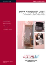
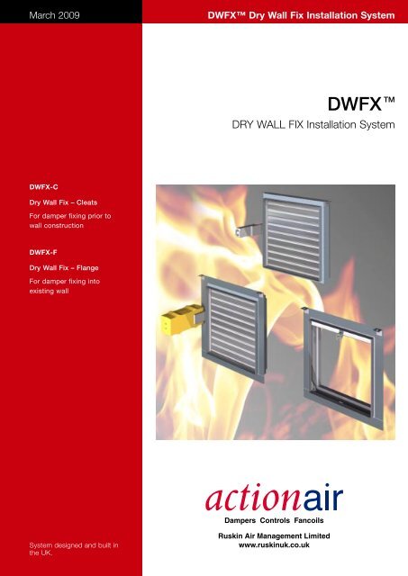
March 2009<strong>DWFX</strong> Dry Wall Fix <strong>Installation</strong> <strong>System</strong><strong>DWFX</strong> TM<strong>DRY</strong> <strong>WALL</strong> <strong>FIX</strong> <strong>Installation</strong> <strong>System</strong><strong>DWFX</strong>-CDry Wall Fix – CleatsFor damper fixing prior towall construction<strong>DWFX</strong>-FDry Wall Fix – FlangeFor damper fixing intoexisting wall<strong>System</strong> designed and built inthe UK.
<strong>DWFX</strong> Dry Wall Fix <strong>Installation</strong> <strong>System</strong><strong>DWFX</strong>-CDry Wall Fix – CleatsSpecificationThe <strong>Actionair</strong> <strong>DWFX</strong>-C installation methodis BRE Tested to BS476 pt 20 for 2 hours.(BRE test report 212065).Suitable for• <strong>Actionair</strong> Fire/Shield• <strong>Actionair</strong> Smoke/Shield• <strong>Actionair</strong> Hot/ShieldThe <strong>Actionair</strong> <strong>DWFX</strong>-C consists of 50mmx 50mm x 3mm steel angle cleats with 14x 24mm oval slots.Fully welded to damper casing for droprod support prior to wall construction.<strong>Installation</strong> Guide1. Mark centre line of damper onceiling/floor.2. Measure cleat hole centres on damper.3. Mark out position of each drop rodeither side of centre line.4. Cut and fit drop rods.5. Position vertically to desired height andsecure damper with appropriatefastenings.6. Continue to fabricate wall, allowing a5mm gap (approx) around damperspigots to permit fitting of ductwork.2 www.actionair.co.uk
<strong>DWFX</strong> Dry Wall Fix <strong>Installation</strong> <strong>System</strong><strong>DWFX</strong>-FDry Wall Fix – FlangeSpecification<strong>Installation</strong> GuideThe <strong>Actionair</strong> <strong>DWFX</strong>-F installation methodis BRE Tested to EN1366-2 for 90 minutes.(BRE test report 220895).Classification (ref BRE assessment225285).• <strong>Actionair</strong> Fire/Shield E90• <strong>Actionair</strong> Smoke/Shield ES60/E90• <strong>Actionair</strong> Hot/Shield ES60/E90The <strong>Actionair</strong> <strong>DWFX</strong>-F consists of a 1.2mmgalvanised steel peripheral flange with50mm x 50mm x 3mm steel angle cleatswith 14 x 24 oval slots, welded to dampercasing for drop rod support.Centre lineof ducting1. Mark out the hole to be cut on onesurface of the wall, using the centre ofthe duct run as a datum. Check thediagonals of the marked out rectangle toensure that it is square.2. Drill the four corners to project therectangle on to the reverse side of thewall. Mark out the hole on the reverse.3. Cut the top and bottom edges of thehole first, then the vertical edges. Do thesame on the reverse.4. Remove the waste material and tidy upall the edges of the hole.5. Frame out the sides of the hole withstudding as used in the wall construction.6. Line the sides of the hole using thesame plasterboard as used in the wallconstruction.<strong>DWFX</strong>-F with Smoke/Shield*7. Drill clearance holes in the damperflange marking out such that anyfasteners used will pass through theboard materials and penetrate thestudding behind. Centres should beapproximately 150mm.8. Place the damper in the hole in thewall. Use some pieces of plasterboard asshims to ensure that the damper isequally positioned in the hole. Push theflange flush to the face of the wall. Screwthe flange to wall. Fit M10 drop rods.9. Fill void with mineral wool10. Finish off with edging, using the sameplasterboard as used in the wall construction.<strong>DWFX</strong>-F with Fire/Shield*Typical installation, refer to ‘Cutting HoleSizes’ on page 4.www.actionair.co.uk3
<strong>DWFX</strong> Dry Wall Fix <strong>Installation</strong> <strong>System</strong><strong>DWFX</strong>-FCutting Hole SizesSmoke/ShieldMeasure damper casing (not overallflanges) Width x HeightCutting hole size =Width = 2 x wall board thickness used+ 2 x 12.5mm clearance all round+ damper casing width*.*For PTC dampers, add an additional30mm to width for snaplock TM driveshroud.Height = 2 x wall board thickness used+ 2 x 12.5mm clearance all round+ damper casing height.Hole tolerance of +/– 5mm applies.ExampleNominal Smoke/Shield PTC damper1000mm x 1000mm using 12.5mm wallboard thickness.Measure casing of damper (1048mmWide x 1073mm High).Add 30mm to width for shroud+ 2 x 12.5mm clearance = 25mm+ 2 x 12.5mm wallboard = 25mm1048 + 25 + 25 + 30 = 1128mm Width1073 + 25 + 25 = 1123mm HeightFire/ShieldMeasure damper casing.Cutting hole size =Width = 2 x wall board thickness used+ 2 x 12.5mm clearance all round+ damper casing width.Height = 2 x wall board thickness used+ 2 x 12.5mm clearance all round+ damper casing height.Hole tolerance of +/– 5mm applies.ExampleNominal Fire/Shield damper 1000mm x1000mm using 12.5mm wall boardthickness.Measure casing of damper (1048mmWide x 1123mm High).+ 2 x 12.5mm clearance = 25mm+ 2 x 12.5mm wallboard = 25mmTherefore cutting hole size= 1098mm Width x 1173mm Length.Hole to Cut Dimension CalculationMeasure casing width ........Add shroud dimension *30Add gap dimension 25Add 2 x typ. board thickness 25Gives hole to cut width = TotalMeasure casing height ........Add gap dimension 25Add 2 x typ. board thickness 25Gives hole to cut height = Total*Smoke/Shield damper only.General Notes: applicable to allcontent of this brochureThese installation methods are forguidance only. <strong>Installation</strong>s will vary andit is likely that it will not be possible tocopy the exact installation methodprescribed in this document. Fire ratingwill vary depending upon installationspecification. It is the responsibility ofothers to gain local authority approvalfor all installations, that includes suitabledesign / materials / workmanship etc.for the structure.M10 diameter steel drop rods minimumare recommended.A fully detailed installation methoddocument is available on the <strong>Actionair</strong>website, or via the <strong>Actionair</strong> CustomerService Department.Quality <strong>System</strong> Assessed to ISO 9001: 2000Ruskin Air Management LimitedRuskin Air Management LimitedSouth Street, Whitstable, Kent CT5 3DU England.Tel: 01227 276100 Fax: 01227 264262Email: sales@actionair.co.uk Website: www.actionair.co.ukRuskin Air Management Limitedis a ISO 9001 and 14001registered companyProduct Data Sheet Part Number LNNN00298.