

SS09024 - Measurement Solutions - FMC Technologies
SS09024 - Measurement Solutions - FMC Technologies
SS09024 - Measurement Solutions - FMC Technologies

Create successful ePaper yourself
Turn your PDF publications into a flip-book with our unique Google optimized e-Paper software.
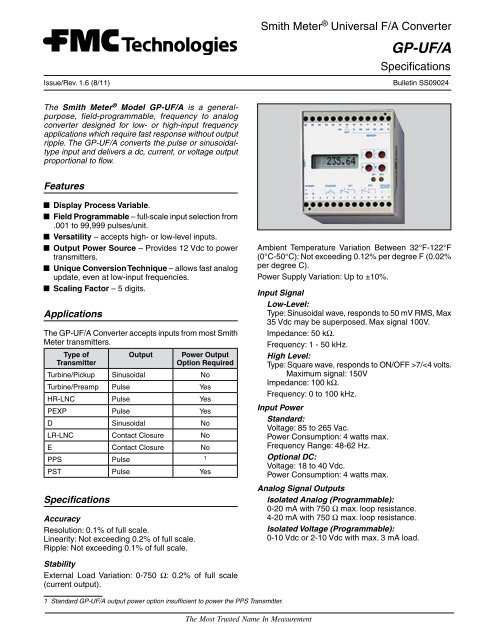
Issue/Rev. 1.6 (8/11)Smith Meter ® Universal F/A ConverterGP-UF/ASpecificationsBulletin <strong>SS09024</strong>The Smith Meter ® Model GP-UF/A is a generalpurpose,field-programmable, frequency to analogconverter designed for low- or high-input frequencyapplications which require fast response without outputripple. The GP-UF/A converts the pulse or sinusoidaltypeinput and delivers a dc, current, or voltage outputproportional to flow.FeaturesDisplay Process Variable.Field Programmable – full-scale input selection from.001 to 99,999 pulses/unit.Versatility – accepts high- or low-level inputs.Output Power Source – Provides 12 Vdc to powertransmitters.Unique Conversion Technique – allows fast analogupdate, even at low-input frequencies.Scaling Factor – 5 digits.ApplicationsThe GP-UF/A Converter accepts inputs from most SmithMeter transmitters.Type ofTransmitterOutputPower OutputOption RequiredTurbine/Pickup Sinusoidal NoTurbine/Preamp Pulse YesHR-LNC Pulse YesPEXP Pulse YesD Sinusoidal NoLR-LNC Contact Closure NoE Contact Closure NoPPS Pulse1PST Pulse YesSpecificationsAccuracyResolution: 0.1% of full scale.Linearity: Not exceeding 0.2% of full scale.Ripple: Not exceeding 0.1% of full scale.Ambient Temperature Variation Between 32°F-122°F(0°C-50°C): Not exceeding 0.12% per degree F (0.02%per degree C).Power Supply Variation: Up to ±10%.Input SignalLow-Level:Type: Sinusoidal wave, responds to 50 mV RMS, Max35 Vdc may be superposed. Max signal 100V.Impedance: 50 kΩ.Frequency: 1 - 50 kHz.High Level:Type: Square wave, responds to ON/OFF >7/
Pulse:Type: Square wave (repeat of input).Voltage: 10 Vdc.Frequency: 0 to 100 kHz.Source Impedance: 1 kΩ.Load: Not less than 10 kΩ.DC Output PowerVoltage: 12 Vdc – standard.Current: 60 mA max. with AC power input.Current: 20 mA max. with DC power input.EnvironmentalAmbient Operating Temperature:30°F to 122°F (0°C to 50°C).EnclosuresStandard:General-purpose NEMA 1.Mounting: Any position – base-mount or snap-on 35mm relay track.Optional:Weatherproof, NEMA 4.Explosion-proof, NEMA 7, Class I, Group D.Ordering InformationTo assure that the GP-UF/A meets all requirements,please specify the following information when ordering:ModelInput PowerType of EnclosureOutput Current SourceModelingExample: GP-UF/A — DC — GGP-UF/ABasic Model DesignationInput PowerAC (85 to 265 Vac)(Standard)DC (18 to 40 Vdc)Programming ProcedureGP-UF/A – AC – GGP-UF/A – AC – N4Available ModelsGP-UF/A – AC – X –GP-UF/A – DC – GGP-UF/A – DC – XEnclosureG – General-Purpose (Standard)N4 – WeatherproofX – Explosion-ProofProgramming is accomplished by using the four keysthat are located at the right side of the display. The keysand their functions are as follows:– This key is used to step through the programparameters sequentially or to advance the selectionof the blinking underlined character.– This key is used to display the descriptive text ofthe parameter that is displayed or to shift to thenext digit to be programmed.P – This key is used to activate or deactivate the programmode. If the display is showing the processvariable, pressing P will put the unit in the programmode. If the unit is in program mode, pressing Pwill take the unit out of program mode and displaythe process variable.E – This key is used to enter the write condition of theparameter that is being displayed. When pressed,the digit will blink and can be altered. Once the digithas been changed, pressing “E” again will writethat value to memory.The standard procedure for programming the unit is asfollows:1. Start programming by pressing “P”.2. Enter the parameter to be changed by pressing “E”.3. Select the required digit to be changed by pressing“ ” until that digit is blinking.4. Move to the required setting by pressing “ ” until therequired digit is blinking.5. Move to the next digit by pressing “ ”.6. When all the required digits have been changed,write the value to memory by pressing “E”.7. Move to the next parameter by pressing “ ”.8. Terminate programming by pressing “P”.Parameters that are not required to be changed can beskipped by continuing to press “ ” until the parameterthat is required to be changed is displayed.If parameter 02 is programmed as locked and the passcode had not been entered in parameter 00, all the parameterscan be read (except the pass code) but can notPage 2 • <strong>SS09024</strong> Issue/Rev. 1.6 (8/11)
e changed. If program parameter 02 is programmed asunlocked, the parameters can be changed without theuse of a pass code. Once the instrument is installed, it isrecommended that parameter 02 be changed to lockedso only authorized personnel who have the pass codecan change the program parameters.ProgrammingDefault SettingsThe unit is shipped from the factory with the followingdefault parameter settings.StepNumberDescription Function Value00 SECRET Pass Number 000001 C. SECRET New Pass Number 000002 ACCESS ? Lock Function 1 = unlocked03 DECP /u Decimals of PulseFactor0 (no decimals)04 /u Pulse Factor 1 (pulse/unit)05 DP FREQ. Decimals of <strong>Measurement</strong>0 (no decimals)06 FMAX High End of Range 00100 (pulse/second)07 FMIN Low End of Range 0000008 TIMEBASE Time Reference 0 = .../second09 ZERO MODE Zero Level 1 = live zero10 OFF-RATE Cut-Off Low End 1% of high end11 PREDIV Input FrequencyDivider12 TMIN Minimum measurementperiod001400The unit can be returned to the default settings at anytime by pressing both the P and when the power isturned on to the unit.Parameters00 – SecretThis four digit parameter is used to protect the unitagainst unauthorized or inadvertent alteration of theprogram parameters. To change the programming ofthe instrument, the operator enters the pass code thathas previously been entered in the unit. If an incorrectpass code is entered, the programming mode willbe cancelled and the display will revert back to themeasurement value. If a value is not entered in thisparameter, the remaining parameters can be viewedbut not changed. The default value when shipped fromthe factory is 0000.01 – C. SECRETThis four digit parameter is used to change the passcode that was originally programmed in the unit. In orderto enter a value in this parameter, a correct value hadto be programmed in parameter 00.02 – ACCESSThis single digit parameter is used during installation andstart-up where parameters must be changed frequently.The options for this parameter are:0 - locked1 - unlockedAfter the installation and start-up process are completed,this parameter should be programmed as 0 (locked) sothat the pass code must be entered before parameterscan be changed. The default value, as shipped from thefactory, is 1 (unlocked).03 – Decimals of pulse factorThis single digit parameter sets the number of decimalplaces that will be used for the number of pulses per oneunit of volume coming from the transmitter. The selectionsfor number of decimal places are as follows:0 - no decimal places (0)1 - one decimal place (0.1)2 - two decimal places (0.01)3 - three decimal places (0.001)The actual number of pulses is programmed in parameter04. The default value for this parameter, as shippedfrom the factory, is 0 (no decimal places).04 – (K-Factor) Number of pulses per one unit ofvolumeThis four or five digit parameter is used to program thenumber of pulses being supplied by the transmitter foreach unit of volume going through the meter. The numberof digits available is dependent on whether a decimalis being used in the number. Most meter manufacturerswill supply the nominal number of pulses per unitvolume being output from the transmitter. The defaultvalue for this parameter, as shipped from the factory,is 1 pulse/unit.Example:Note: Parameter 08 must be set to (1) for minutes.To display in gallons per minute utilizing a 1000 P/RevTransmitter and a Smith G6 meter with 5:1 gallon gearing:Output pulses = (1000 Pulses/Rev) / 5 gal = 200 Pulsesper gallon.K-Factor = 200 P/Gal.To display in dekaliters per minute utilizing a 1000 P/RevTransmitter and a Smith G6 meter with 5:1 dekalitergearing:Output pulses = (1000 Pulses/Rev) / 5 dekaliter = 200pulses per decaliter and a Smith G6 meter with 5:1dekaliter gearing.K-Factor = 200 P/Dekaliter.To display in dekaliters per minute utilizing a 1000 P/RevTransmitter and a Smith G6 meter with 5:1 dekallitergearing:Output pulses = (1000 P/Rev) / 5 dekaliter = 200 Pulsesper dekaliter1 dekaliter = 10 litersK-Factor = 10 liters x 200 P/dekaliterF-Factor = 2000 P/litersIssue/Rev. 1.6 (8/11) <strong>SS09024</strong> • Page 3
Note: The GP-UF/A does not offer an hour time baseselection in parameter 08, therefore ro display in unitsper hour the K-Factor must be divided by 60. The displayhas a fixed label if units/min, however using the followingexample the actual amount will be in units per hour.To display in Barrels per Hour (BPH) utilizing a 1000P/Rev Transmitter and a Smith M16 meter with 1:1 Barrelgearing (Max flow rate of 12,500 BPH) use the followingexample; this will require that parameter 03 be setfor (2) decimal places and parameter 06 be set to themaximum flow rate in BPH:M16 output pulses = (1000 Pulses/Rev) x BBL = 1000pulses per BBL(1000 P/BBL) / 60 minutes.hour = 16.66K-Factor = 16.66 to display in BPHTo display in Barrels per Hour (BPH) utilizing a Smith 10"Sentury Turbine Meter (Max flow rate 12,000BPH) usethe following example; this will require that parameter03 be set for (2) decimal places and parameter 06 beset to the maximum flow rate in BPH:Nominal K Factor for a 10" Sentury = 525P/BBL(525 P/BBL) / 60 minutes /hour = 8.75K-Factor = 8.75 to display in BPH05 – Decimals of measurement (DP FREQ.)This single digit parameter sets the number of decimalplaces for the display readings and the range definition.The selections for number of decimal places areas follows:0 - no decimal places (0)1 - one decimal place (0.1)2 - two decimal places (0.01)3 - three decimal places (0.001)The actual ranges are programmed in parameters 06and 07. The default value for this parameter, as shippedfrom the factory, is 0 (no decimal places).06 – Maximum frequency (FMAX)This four or five digit parameter allows the operator toprogram the maximum frequency that will provide eitherthe 10V or 20 mA signal from the converter. If there is adecimal point programmed in parameter 05, this will bea four digit entry. If no decimal point is entered, this willbe a five digit entry. The default value for this parameter,as shipped from the factory, is 00100 pulses/second.Examples:Smith G6 meter is rated for 1000 GPM Max or 3750LPM Max.Smith M16 is rated 12500 BPH or 2000 M3/Hr(see notes under parameter 04)07 – Minimum frequency (FMIN).This four or five digit parameter allows the operator toprogram the minimum frequency that will provide a 2Vor a 4 mA signal from the converter. If there is a decimalpoint programmed in parameter 05, this will be a fourdigit entry. If no decimal point is entered, this will be afive digit entry. The default value for this parameter, asshipped from the factory, is 0 pulses/second.08 – Time reference (TIME BASE)This single digit entry allows the operator to set upthe time base for the variable displayed as well as therange definitions in parameters 06 and 07. The optionsare as follows:0 = seconds1 = minutesThe default value for this parameter is seconds.09 – Zero level (ZERO MODE)This single digit entry allows the operator to set up thezero level of output. The options are as follows:0 = zero (0)1 = level zero (4 mA or 2V)A selection of 0 will set the minimum output to be either0 mA or 0V depending on how the unit is wired. A selectionof 1 will set the minimum output to be either 4 mAor 2V depending how the output is wired. The defaultvalue for this parameter is 1 (level zero).10 – Low flow cutoff (OFF-RATE)This two digit percentage entry allows the operator toprogram a low flow cutoff for the meter. When this levelis reached, the output is cutoff to its zero level (unlessthe low end is programmed to an even higher level). Thelevel is programmed as a percentage of the maximumfrequency programmed in parameter 06.The default value for this parameter is 1% of the maximumfrequencyExample: If programmed for 10% of 1000 GPM the Lowflow cutoff would be 100 GPM11 – Input divide (PREDIV)This three digit entry provides the operator the abilityto divide the incoming pulses by a number from 001 to255. The default value for this parameter is 001.12 – Minimum <strong>Measurement</strong> Period (TMIN)This five digit entry is used to achieve an averaging of theinput frequency measurements over the programmedtime period. This entry will help stabilize cyclic measurements.Valid entry range if from 00005 to 99999. Entryis in milliseconds, recommended minimum setting is400 milliseconds, smaller entries can be used for higherfrequency applications.Example: for 2 second averaging, enter 2000.Page 4 • <strong>SS09024</strong> Issue/Rev. 1.6 (8/11)
Wiring DiagramTerminal1 L1 (85-265 Vac), + (18-40 Vdc)2 N/L2 (85-265 Vac), - (18-40 Vdc)3 No connection4 Jumper for voltage output5 } otherwise no connectionNot Used6 + output (mA and V)7 - mA output } Activeoutput8 - V output9 High level pulse input(square wave V)10 Low level pulse input(sine wave mV)11 +8V output (Namur sensors)12 +12V output13 Common V output14 Shield15 Repeat of input pulse16 GroundShield 8V V-V 12V ~mVRepeatOutput ProgrammingA - Jumper Terminals 4 and 5 for voltage output.B - Current output from Terminals 6 (+) to 7 (-) .Voltage output from Terminals 6 (+) to 8 (-) .AL1 L2 NC + -I -VPower SupplyV/IIssue/Rev. 1.6 (8/11) <strong>SS09024</strong> • Page 5
Input Wiring DiagramsSignal9Signal9Black+12 Vdc12ShieldLNCPulser(Contact Type)+12 Vdc12CommonRedWhitePEXPor HR-LNC1413Signal+12 Vdc1012Common13ShieldPickupCoil onTurbine MeterCommon13Signal513Smith PA-6Preamp76Turbine MeterPickup Coil149Shield14Functional DiagramActive 4 - 20 mA OutputVmV0V91013Signal ConditionerGalvanicIsolationF/A - Converter45678Jumper forVoltage Output+- mA- VActive4 - 20 mAOutput140VPulse 15Output1k1211+12V/60 mA+8 VTransmitter SupplyPage 6 • <strong>SS09024</strong> Issue/Rev. 1.6 (8/11)
DimensionsInches (mm)35 mmRail Mount Only2.9"(75)2.7"(70)Weight: Approx. 0.9 lb (0.4 kg).Note: Dimensions – Inches to the nearest tenth (millimetres to the nearest whole mm), each independently dimensioned from respectiveengineering drawings.4.3"(110)Dimensions – Explosion-Proof HousingInches (mm)2 Mounting Bolts 3/8" (9) Diameter6.0"(152)7.4"(189)3.0"(76)3.0"(76)1.5"(38)3.9"(99).500 - 14 NPT Conduit Entrance(Typ. 2 Places)7.8"(197)6.7"(170)6.4"(164)Note: Dimensions – Inches to the nearest tenth (millimetres to the nearest whole mm), each independently dimensioned from respectiveengineering drawings.Issue/Rev. 1.6 (8/11) <strong>SS09024</strong> • Page 7
Revisions included in <strong>SS09024</strong> Issue/Rev. 1.6 (8/11):LP Loop-powered output source removed.The specifications contained herein are subject to change without notice and any user of said specifications should verify from the manufacturer that the specifications are currentlyin effect. Otherwise, the manufacturer assumes no responsibility for the use of specifications which may have been changed and are no longer in effect.Contact information is subject to change. For the most current contact information, visit our website at www.fmctechnologies.com/measurementsolutions and click on the“Contact Us” link in the left-hand column.Headquarters:500 North Sam Houston Parkway West, Suite 100, Houston, TX 77067 USA, Phone: +1 (281) 260 2190, Fax: +1 (281) 260 2191<strong>Measurement</strong> Products and Equipment:Erie, PA USA +1 (814) 898 5000Ellerbek, Germany +49 (4101) 3040Barcelona, Spain +34 (93) 201 0989Beijing, China +86 (10) 6500 2251Buenos Aires, Argentina +54 (11) 4312 4736Burnham, England +44 (1628) 603205Dubai, United Arab Emirates +971 (4) 883 0303Los Angeles, CA USA +1 (310) 328 1236Melbourne, Australia +61 (3) 9807 2818Moscow, Russia +7 (495) 5648705Singapore, +65 6861 3011Visit our website at www.fmctechnologies.com/measurementsolutionsPrinted in U.S.A. © 8/11 <strong>FMC</strong> <strong>Technologies</strong> <strong>Measurement</strong> <strong>Solutions</strong>, Inc. All rights reserved. <strong>SS09024</strong> Issue/Rev. 1.6 (8/11)Integrated <strong>Measurement</strong> Systems:Corpus Christi, TX USA +1 (361) 289 3400Kongsberg, Norway +47 (32) 286700Dubai, United Arab Emirates +971 (4) 883 0303


