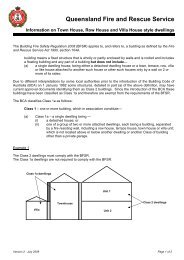
Guidelines - Queensland Fire and Rescue Service
Guidelines - Queensland Fire and Rescue Service
Guidelines - Queensland Fire and Rescue Service

You also want an ePaper? Increase the reach of your titles
YUMPU automatically turns print PDFs into web optimized ePapers that Google loves.
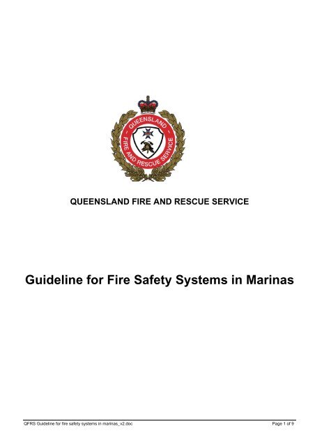
QUEENSLAND FIRE AND RESCUE SERVICEGuideline for <strong>Fire</strong> Safety Systems in MarinasQFRS Guideline for fire safety systems in marinas_v2.doc Page 1 of 9
Legislative BackgroundQFRS Guideline for <strong>Fire</strong> Safety Systems in MarinasIn the Sustainable Planning Regulation 2009, Schedule 7, Table 2 - Other development madeassessable under schedule 3 (whether or not the development is also assessable under a planningscheme, temporary local planning instrument or preliminary approval to which section 242 of the Actapplies), Part 18, the <strong>Queensl<strong>and</strong></strong> <strong>Fire</strong> <strong>and</strong> <strong>Rescue</strong> <strong>Service</strong> is identified as an advice agency foroperational work made assessable under schedule 3, part 1, table 4, item 5, that is—(a) tidal work; <strong>and</strong>(b) involves a marina, as defined under the Transport Operations (Marine Pollution) Regulation2008, with more than 6 vessel berths.InterpretationHaving regard to the location of the marina, the size of the marina in relation to the length <strong>and</strong> number ofberths, the size of vessels that a berth could accommodate <strong>and</strong> finger configuration; the followingguideline details the minimum required <strong>Fire</strong> Safety Installations.The objective is that adequate fire protection should be provided to:• Restrict fire growth <strong>and</strong> minimise damage at the berth of origin;• Prevent fire spread to adjoining berths; <strong>and</strong>• Suit the <strong>Queensl<strong>and</strong></strong> <strong>Fire</strong> <strong>and</strong> <strong>Rescue</strong> <strong>Service</strong> (QFRS) operational requirements.LimitationsIn relation to fire hydrant system design this guideline sets out the minimum requirements for fire fightingwater flows <strong>and</strong> pressures. The fire hydrant system is designed to provide sufficient water to attack fireswhich produce a heat release rate of up to 5 MW.Designers of these systems must ensure that where heat release rates exceed 5 MW furtherconsideration needs to be given to the water supplies required to combat a fire for that particular marinadesign.DefinitionsAny definition that is applicable to marinas in this guideline will be of the same definition as used inAustralian St<strong>and</strong>ard 3962-2001.<strong>Fire</strong> Hydrants Systems - Acceptable Design SolutionsThe following 4 fire hydrant system design solutions have taken into account the particular location <strong>and</strong>environment which they are expected to operate in. Various design options are detailed below, they alsoinclude diagrams to provide further explanation of the fire hydrant system requirements. The diagramsare for illustrative purposes only <strong>and</strong> are therefore not to scale. An explanation of the symbols used hasbeen provided in Appendix A.QFRS Guideline for fire safety systems in marinas_v2.doc Page 2 of 9
<strong>Fire</strong> Hydrant System – Design Solution #1For marina designs that allow for 60 metre hose coverage from a <strong>Fire</strong> <strong>Service</strong> pumping appliance(Diagram 1) the QFRS requires:• A double-headed pillar hydrant (feed hydrant) to be installed within 20 metres of hard st<strong>and</strong>ing<strong>and</strong> be located as close as practical to the entrance of each gangway preferably on the shoreline;<strong>and</strong>• The main deck of each moored vessel is covered by a 10 metre hose stream; <strong>and</strong>• The fire main must be capable of supplying water at flow rates <strong>and</strong> pressures necessary tofacilitate the operation of effective fire fighting jets via a <strong>Fire</strong> <strong>Service</strong> pumping appliance–minimum requirement 10L/s with a residual pressure of 200 kPa (feed hydrant).Diagram 1QFRS Guideline for fire safety systems in marinas_v2.doc Page 3 of 9
<strong>Fire</strong> Hydrant System – Design Solution #2For marina designs that can achieve 60 metre hose coverage from a <strong>Fire</strong> <strong>Service</strong> pumping appliancebut the reticulated water supply cannot meet the minimum required flow <strong>and</strong> pressure of 10L/s with aresidual pressure of 200 kPa (Diagram 2) QFRS requires:• A one hour tank supply with a fixed hard suction point; <strong>and</strong>• Facilities that comprise fixed hard suction complete with foot valve <strong>and</strong> strainer to allow aQFRS pumper to utilise the static water supply at all times including low tide. The maximumpump lift height is to be no greater then 5 metres which is measured from the hard st<strong>and</strong>ing<strong>and</strong> the low tide level; <strong>and</strong>• Hard st<strong>and</strong>ing is to be provided within 4.5 metres of both suction points.All suction <strong>and</strong> hose fittings must meet the QFRS operational requirements regarding thespecifications for tank supply points:• A hard suction point must be incorporated on all water storage tanks.;• The suction point must be fitted with a Female coupling (suction connection):o Type: British Coventryo Diameter: 125mm female couplingo Thread size: 3 threads per inch• This hard suction point is to be located adjacent to the tank;• In order not to over tax a priming pump the maximum length of pipe work from water storagetank or static supply to the outlet in a booster cabinet must be no more than 15 metres with alift of no more than 5 metres;• The pipe should be of a type suitable to withst<strong>and</strong> pressures below atmospheric;• Size of suction pipe from tank must be 150mm;• Connection between 150mm suction pipe <strong>and</strong> 125mm connection must not narrow to lessthan 125mm;• Tank capacity <strong>and</strong> tank contents indicator as per Section 5 AS 2419.1-2005• To prevent fouling <strong>and</strong> to facilitate maintenance, suction pick-ups can be of the type that canbe raised or lowered.1hrSupplyMax lift 5mavailable atlow tide10m4.5mHARDSTANDHARDSTAND60mHDiagram 2QFRS Guideline for fire safety systems in marinas_v2.doc Page 4 of 9
<strong>Fire</strong> Hydrant System – Design Solution #3The QFRS requires a hydrant booster <strong>and</strong> cabinet assembly (Diagram 3) to be installed for marinadesigns where:• The coverage exceeds the 60 metre distances identified in diagrams 1 <strong>and</strong> 2; or• Berth/s are provided to serve vessels greater than 15 metres in length, <strong>and</strong> such berths arelocated greater than 30 metres from the shoreline (measured along the walkway).The booster assembly is to be constructed to the design provided in Australian St<strong>and</strong>ard 2419.1. Thefeed hydrants within the booster assembly must provide a flow of 10L/s with a residual pressure of 200kPa.Where the pressures <strong>and</strong> flows cannot be achieved refer to <strong>Fire</strong> Hydrant System – Design Solution #4.• The hydrant booster cabinet must be installed within 8 metres of hard st<strong>and</strong>ing; <strong>and</strong>The hydrant system installed on the shoreline <strong>and</strong> along the marina should consist of:-• A double-headed pillar hydrant (attack hydrant) must be installed <strong>and</strong> located as close aspractical to the entrance of each gangway preferably on the shoreline; <strong>and</strong>• Additional single outlet hydrants are to be provided at suitable locations to ensure that all partsof the marina are covered by a 30 metre length of hose; <strong>and</strong>• The main deck of each moored vessel is covered by a 10 metre hose stream; <strong>and</strong>• The hydrant installed at the end of a walkway is to be a dual outlet hydrant; <strong>and</strong>• When boosted the two most hydraulically disadvantaged hydrants must achieve a flow of 5L/sec @ a residual pressure of 700 kPa.Vehicular access <strong>and</strong> hard st<strong>and</strong>ing must be provided within 8m of the booster assembly. Both musthave the load bearing capacity, unobstructed height <strong>and</strong> width to manoeuvre a fire appliance.DoubleHeadFeed Hyd10L/s @200kpa30mHARD STAND8mBOOSTER10m10mAt boost 2x 5L/s @700 kpaH30mH HH H10m10m10m30m 30m 30mDiagram 3QFRS Guideline for fire safety systems in marinas_v2.doc Page 5 of 9
<strong>Fire</strong> Hydrant System – Design Solution #4For marina designs where a booster is required but the feed hydrants are unable to provide 10L/s with aresidual pressure of 200 kPa, the QFRS requires the following:-• A one hour tank supply with a fixed hard suction point; <strong>and</strong>• Facilities that comprise fixed hard suction complete with foot valve <strong>and</strong> strainer to allow aQFRS pumper to utilise the static water supply at all times including low tide. The maximumpump lift height is to be no greater then 5 m which is measured from the hard st<strong>and</strong>ing <strong>and</strong>the low tide level; <strong>and</strong>• Hard st<strong>and</strong>ing is to be provided within 4.5 metres of both suction points.All suction <strong>and</strong> hose fittings must meet the QFRS operational requirements regarding thespecifications for tank supply points as detailed in <strong>Fire</strong> Hydrant System – Design Solution #2.Marina Layout Diagram 4Recommendation:• Marking of hydrant location should be a consideration in the development of the hydrantsystem. This may be achieved by placing blue cats eyes at the edge of the walkway adjacentto the hydrants.QFRS Guideline for fire safety systems in marinas_v2.doc Page 6 of 9
<strong>Fire</strong> Hose ReelsThe QFRS requires fire hose reels which comply with Australian St<strong>and</strong>ard 1221 to be provided <strong>and</strong>located so that:• No part of a berth is beyond the reach of the nozzle end of two fully extended reels; <strong>and</strong>• The maximum length of hose on any reel is 36 metres; <strong>and</strong>• At least one reel is located on the shoreline side of the first berth on each main walkway, atthe seaward end of each walkway, <strong>and</strong> at each intersection of each secondary walkway <strong>and</strong>main walkway; <strong>and</strong>• Additional hose reels are spaced along each walkway that provides berth facilities, <strong>and</strong> bespaced so that the nozzle from two hose reels are capable of serving each berth; <strong>and</strong>• The two most hydraulically disadvantaged reels (operated simultaneously) each provide aminimum water flow rate of 0.63 L/sec at a running pressure of not less than 275 kPa.Where the required flow rate <strong>and</strong> running pressure cannot be achieved at all times from the normal watersupply, a booster pump should be provided which:• Is self-priming; <strong>and</strong>• Has the capacity to supply water at a minimum rate of 1.26 L/s at the required runningpressure; <strong>and</strong>• Operates automatically upon the flow of water through any hose reel.Protection for fire hose reels from aggressive environments should be considered as per AustralianSt<strong>and</strong>ard 1221.These hose reel provisions are in line with those in Australian St<strong>and</strong>ard 3962-2001.<strong>Fire</strong> Alarms• A manually activated electric fire alarm that is audible throughout the marina <strong>and</strong> isdistinguishable from any other signal should be provided. This alarm should be interfacedwith any installed fire alarm monitoring system <strong>and</strong> have a battery back-up system as anintegral component.• Sounders should be installed at each hose reel or at any other location that is deemedsuitable so that the warning signal is audible throughout the marina.• Manual Call Points (MCPs) to activate the alarm system should be located adjacent to eachfire hose reel <strong>and</strong> at the shore entrance to each walkway of the marina. Each MCP to have asign advising:” Not connected to fire brigade. In the event of fire DIAL 000”.• The system should also activate an alarm at any shore based marina management office.Maintenance of EquipmentAll installed fire safety installations must be protected from aggressive environments <strong>and</strong> be maintainedin accordance with the requirements of <strong>Queensl<strong>and</strong></strong> Development Code MP 6.1, other than the flow <strong>and</strong>pressure performance requirements for fire hydrant systems which should be maintained in accordancewith the requirements indicated in this guideline.<strong>Fire</strong> ProceduresAll staff should receive adequate instruction in the use of fire fighting equipment <strong>and</strong> the procedures to befollowed in the event of a fire.QFRS Guideline for fire safety systems in marinas_v2.doc Page 7 of 9
Water SupplyThe pipe work for the water supply of the fire hydrant system should be in line with the requirements ofClause 6.3 of Australian St<strong>and</strong>ard 3962-2001.The fire main shall be tested to 1350kPa unassisted or 1700kPa if fed by a hydrant booster.OccupationMarinas should not allow for vessels to berth until all of the installations in this guideline have beeninstalled, tested <strong>and</strong> approved.Australian St<strong>and</strong>ard 3962-2001 has been considered in the development of these guidelines.QFRS Guideline for fire safety systems in marinas_v2.doc Page 8 of 9
APPENDIX A – Marina Layout Diagram LegendQFRS Guideline for fire safety systems in marinas_v2.doc Page 9 of 9