G-Series Programmer - MTS Sensors
G-Series Programmer - MTS Sensors
G-Series Programmer - MTS Sensors

Create successful ePaper yourself
Turn your PDF publications into a flip-book with our unique Google optimized e-Paper software.
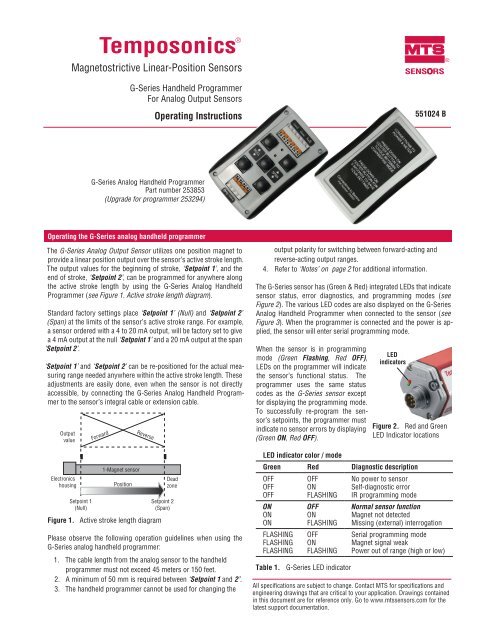
Temposonics ®Magnetostrictive Linear-Position <strong>Sensors</strong>G-<strong>Series</strong> Handheld <strong>Programmer</strong>For Analog Output <strong>Sensors</strong>Operating InstructionsSENSORS551024 B®G-<strong>Series</strong> Analog Handheld <strong>Programmer</strong>Part number 253853(Upgrade for programmer 253294)Operating the G-<strong>Series</strong> analog handheld programmerThe G-<strong>Series</strong> Analog Output Sensor utilizes one position magnet toprovide a linear position output over the sensor’s active stroke length.The output values for the beginning of stroke, ‘Setpoint 1’, and theend of stroke, ‘Setpoint 2’, can be programmed for anywhere alongthe active stroke length by using the G-<strong>Series</strong> Analog Handheld<strong>Programmer</strong> (see Figure 1. Active stroke length diagram).Standard factory settings place ‘Setpoint 1’ (Null) and ‘Setpoint 2’(Span) at the limits of the sensor’s active stroke range. For example,a sensor ordered with a 4 to 20 mA output, will be factory set to givea 4 mA output at the null ‘Setpoint 1’ and a 20 mA output at the span‘Setpoint 2’.‘Setpoint 1’ and ‘Setpoint 2’ can be re-positioned for the actual measuringrange needed anywhere within the active stroke length. Theseadjustments are easily done, even when the sensor is not directlyaccessible, by connecting the G-<strong>Series</strong> Analog Handheld <strong>Programmer</strong>to the sensor’s integral cable or extension cable.OutputvalueElectronicshousingSetpoint 1(Null)Forward1-Magnet sensorPositionReverseFigure 1. Active stroke length diagramDeadzoneSetpoint 2(Span)Please observe the following operation guidelines when using theG-<strong>Series</strong> analog handheld programmer:1. The cable length from the analog sensor to the handheldprogrammer must not exceed 45 meters or 150 feet.2. A minimum of 50 mm is required between ‘Setpoint 1 and 2’.3. The handheld programmer cannot be used for changing theoutput polarity for switching between forward-acting andreverse-acting output ranges.4. Refer to ‘Notes’ on page 2 for additional information.The G-<strong>Series</strong> sensor has (Green & Red) integrated LEDs that indicatesensor status, error diagnostics, and programming modes (seeFigure 2). The various LED codes are also displayed on the G-<strong>Series</strong>Analog Handheld <strong>Programmer</strong> when connected to the sensor (seeFigure 3). When the programmer is connected and the power is applied,the sensor will enter serial programming mode.When the sensor is in programmingmode (Green Flashing, Red OFF),LEDs on the programmer will indicatethe sensor’s functional status. Theprogrammer uses the same statuscodes as the G-<strong>Series</strong> sensor exceptfor displaying the programming mode.To successfully re-program the sensor’ssetpoints, the programmer mustindicate no sensor errors by displaying(Green ON, Red OFF).LED indicator color / modeGreen Red Diagnostic descriptionOFFOFFOFFONONONFLASHINGFLASHINGFLASHINGTable 1.OFFONFLASHINGOFFONFLASHINGOFFONFLASHINGG-<strong>Series</strong> LED indicatorLEDindicatorsFigure 2. Red and GreenLED Indicator locationsNo power to sensorSelf-diagnostic errorIR programming modeNormal sensor functionMagnet not detectedMissing (external) interrogationSerial programming modeMagnet signal weakPower out of range (high or low)All specifications are subject to change. Contact <strong>MTS</strong> for specifications andengineering drawings that are critical to your application. Drawings containedin this document are for reference only. Go to www.mtssensors.com for thelatest support documentation.
Operating the G-<strong>Series</strong> Analog handheld programmerTo adjust your programmer settings, perform the following steps:1. Connect the programmer to the sensor’s 6 wires (using aintegral cable or extension cable) as shown in Figure 3 Sensorconnections. The 4 connections at the bottom of the programmerare for the 24 Vdc power supply and a multimeter. Switchon the power supply. The sensor will enter serial programmingmode, then the sensor’s LEDs will display (GreenFlashing, Red Off). The LEDs on the handheld programmermust display (Green ON, Red OFF to continueprogramming successfully.2. Move the position magnet to the appropriate ‘Setpoint 1’position. Do not allow the magnet to move until step 4. Use‘Null’ up or ‘Null’ down buttons to increase or decrease theoutput shown on the multimeter, (press andhold the button for at least a half second).3. The increments by which the value is adjusted can be changedfrom coarse to fine by pressing the programmers’ centerbutton. Coarse mode adjust yields output changesequivalent to 3 - 5 mm steps. Fine mode adjust yields outputchanges equivalent to 0.35 mm steps for ‘Null’ adjustmentsand 0.7 mm steps for ‘Span’ adjustments.4. Move the position magnet to the Setpoint 2 position.Do not allow the magnet to move until step 5, Use ‘Span’Up or ‘Span’ Down buttons to increase or decrease the outputshown on the multimeter.5. To fine-tune the adjustment, repeat steps 2 and 4. Use the finemode adjustment feature if necessary. When both ‘Setpoint 1’and ‘Setpoint 2’ have the appropriate output values, continueto step 6.6. After all changes are made, press and hold the programmer’scenter button for 3 seconds. The programmer will confirmthat new settings have been saved by briefly flashing both theGreen and Red LEDs. The programmer’s LEDs will thenchange to indicate normal sensor functionality (Green ON,Red OFF).Wire ColorRed or BrownWhiteGreenYellowGrayPinkRed orBrownWhiteGreenYellowGrayPinkFigure 3.Notes:ConnectionPower 24Power 0RS-485 -RS-485 +Output +Output -Sensor connections<strong>Programmer</strong> LEDsMeter +Meter -0 Vdc24 Vdc1. G-<strong>Series</strong> Analog sensor outputs are adjustable over the entire activestroke length. The minimum adjustment increment is 0.35 mm, andthe minimum spacing between Setpoint 1 and Setpoint 2 is 50 mm.2. Changing the output polarity for switching between forward-actingand reverse-acting outputs should not be attempted with the Handheld<strong>Programmer</strong> (see Figure 1). Instead, use the G-<strong>Series</strong> PC SetupSoftware to program the sensor for a different output range. Due tothe G-<strong>Series</strong> method of processing, (unlike the R-<strong>Series</strong> Analogsensor), changing the output polarity by only adjusting the setpointvalues will limit the output range or add unnecessary cycle time.3. If the sensor had been previously re-programmed to significantlyreduce the distance between setpoints, then it may be necessary tomake only small changes when re-programming the sensor again.Since the output values are limited in range, it may be necessary toincrease the stroke distance by performing multiple programmingcycles. To increase the distance between the setpoints again, usesmall changes for the new locations of Setpoint 1 and/or Setpoint 2.Perform the steps 2 through 6 to save the new settings. Repeat thewhole procedure, as needed, to get additional distance betweensetpoints.Part Number: 10-08 551024 Revision B<strong>MTS</strong> and Temposonics, and are registered trademarks of <strong>MTS</strong> Systems Corporation.All other trademarks are the property of their respective owners.All Temposonics sensors are covered by US patent number 5,545,984. Additional patents are pending.Printed in USA. Copyright © 2008 <strong>MTS</strong> Systems Corporation. All Rights Reserved in all media.®UNITED STATES<strong>MTS</strong> Systems Corporation<strong>Sensors</strong> DivisionGERMANY<strong>MTS</strong> Sensor TechnologieGmbH & Co. KGJAPAN<strong>MTS</strong> <strong>Sensors</strong> TechnologyCorporationSENSORS3001 Sheldon DriveCary, NC 27513Tel: (800) 633-7609Fax: (919) 677-0200(800) 498-4442www.mtssensors.comsensorsinfo@mts.comAuf dem Schüffel 9D - 58513 LüdenscheidTel: +49 / 23 51 / 95 87-0Fax: +49 / 23 51 / 56 491www.mtssensor.deinfo@mtssensor.de737 Aihara-cho, Machida-shiTokyo 194-0211, JapanTel: +81 (42) 775 / 3838Fax: +81 (42) 775 / 5516www.mtssensor.co.jpinfo@mtssensor.co.jp