View File - Development Services - City of Oxnard
View File - Development Services - City of Oxnard
View File - Development Services - City of Oxnard

You also want an ePaper? Increase the reach of your titles
YUMPU automatically turns print PDFs into web optimized ePapers that Google loves.
CONTENTS6.2.2 Base Case and Phase 1 Scenarios.............................................................. 846.2.3 Phase 2 Scenarios........................................................................................ 897.0 Summary and Conclusions................................................................................................ 957.1 Phase 1 Scenarios..................................................................................................... 957.1.1 Groundwater Recharge Using Recycled Water ..................................... 957.1.2 Groundwater Recovery for Potable Use ................................................. 967.1.3 Reduction in Overdraft.............................................................................. 967.2 Phase 2 Scenarios..................................................................................................... 987.2.1 Groundwater Recharge Using Recycled Water ..................................... 987.2.2 Groundwater Recovery for Potable Use ................................................. 987.2.3 Reduction in Overdraft............................................................................ 1018.0 References........................................................................................................................... 103W112003002SCO LW1458.DOC/ 033390002III
CONTENTSTablesSection 1.0 – IntroductionNoneSection 2.0 – Environmental SettingNoneSection 3.0 – Water Supply and Demand3-1 UWCD and <strong>Oxnard</strong> Groundwater Quality3-2 <strong>City</strong> Blended Water Quality3-3 PHWA Water Quality3-4 Agricultural Water Supply and DemandSection 4.0 – GREAT Program Project Description4-1 Phase 1 and Phase 2 GREAT Program Elements Summary TableSection 5.0 – Historical Groundwater Flow ModelingNoneSection 6.0 – GREAT Program Groundwater Flow Modeling6-1 Scenarios for Model Simulations6-2 Hydrology for Model SimulationsW112003002SCO LW1458.DOC/ 033390002IV
CONTENTSFiguresSection 1.0 – Introduction1-1 Regional Project VicinitySection 2.0 – Environmental Setting2-1 Groundwater Basins and the Santa Clara-Calleguas Hydrologic Unit2-2 Geographic Features2-3 Groundwater Basins and UWCD Recharge and Conveyance Facilities2-4 Average Monthly Precipitation and Temperature2-5 Annual Precipitation and Cumulative Departure from Average Precipitation2-6 Daily Mean Streamflow Flow2-7 Surface Geology <strong>of</strong> the Santa Clara-Calleguas Groundwater Basin2-8 Stratigraphic Column and Related Aquifer Designations2-9 Groundwater Monitoring Locations2-10 USGS Hydrogeologic Cross Sections B-B’, C-C’, and D-D'2-11 DWR 1976 Schematic Cross Section2-12 USGS Simulated Hydrologic Budgets2-13 Locations <strong>of</strong> Wells for <strong>Oxnard</strong> Plain Area Hydrographs2-14 Hydrographs for the <strong>Oxnard</strong> Plain Area2-15 USGS Groundwater Level Hydrographs, UAS2-16 USGS Groundwater Level Hydrographs, LAS2-17 USGS Groundwater Level Hydrographs, Depth-Specific Wells2-18 Groundwater Elevations, UAS, Spring and Fall 20022-19 Groundwater Elevations, LAS, Spring and Fall 20022-20 Reported Groundwater Extractions, UAS and LAS, 20022-21 Total Dissolved Solids Concentrations, UAS and LAS, 20022-22 Chloride Concentrations, UAS and LAS, 20022-23 Chloride Concentration Trends, UAS and LAS2-24 Total Dissolved Solids and Nitrate Concentrations, Forebay, 20012-25 Subsidence on the <strong>Oxnard</strong> PlainSection 3.0 – Water Supply and Demand3-1 <strong>Oxnard</strong> Plain Water Purveyor Service Areas3-2 Existing Water Facilities3-3 Santa Clara River Flow and Diversions at the Freeman Diversion3-4 Santa Clara River Water Quality at the Freeman Diversion3-5 Agriculture and Pumping along PTP Delivery System3-6 Agriculture and Pumping along PVCWD Delivery System3-7 Agriculture and Pumping along Ocean <strong>View</strong> Pipeline3-8 Agriculture and Pumping in Duck Club Area3-9 <strong>City</strong> <strong>of</strong> <strong>Oxnard</strong> Water Supply and Demand3-10 Agricultural Water Supply and Demand, By Area3-11 Agricultural Water supply and Demand, All AreasW112003002SCO LW1458.DOC/ 033390002V
CONTENTSSection 4.0 – GREAT Program Project Description4-1 Overview <strong>of</strong> Project Study Area and Major Project Components4-2 Phase 1 GREAT Program Elements4-3 Phase 2 GREAT Program Elements4-4 Recycled Water Distribution Areas4-5 <strong>City</strong> Water Yard Conceptual Site Plan4-6 Phase 2 Recycled Water ASR OpportunitiesSection 5.0 – Historical Groundwater Flow Modeling5-1 Groundwater Basins, Watershed, and USGS Model Grid5-2 UWCD Updated Model Grid, Regional Area5-3 UWCD Updated Model Grid, Local AreaSection 6.0 – GREAT Program Groundwater Flow Modeling6-1 Model Cumulative Departure from Average Precipitation for Simulations6-2 Key Well Locations for Hydrographs to Evaluate Results <strong>of</strong> Simulations6-3 Historical Groundwater Level Hydrographs for Key Well Locations6-4 Index Well Locations to Evaluate Percent Overdraft Reduction, UAS6-5 Index Well Locations to Evaluate Percent Overdraft Reduction, LAS6-6 2000 Simulated Groundwater Levels, UAS, Baseline Conditions6-7 2000 Simulated Groundwater Levels, LAS, Baseline Conditions6-8 2020 Simulated Groundwater Levels, UAS, Base Case6-9 2020 Simulated Groundwater Levels, LAS, Base Case6-10 2020 Simulated Groundwater Levels, UAS, Scenario 1a6-11 2020 Simulated Groundwater Levels, LAS, Scenario 1a6-12 2020 Simulated Groundwater Levels, UAS, Scenario 1b6-13 2020 Simulated Groundwater Levels, LAS, Scenario 1b6-14 2020 Simulated Groundwater Levels, UAS, Scenario 1c6-15 2020 Simulated Groundwater Levels, LAS, Scenario 1c6-16 Historical and Simulated Groundwater Levels, Base Case and Phase 16-17 2020 Simulated Groundwater Levels, UAS, Scenario 2a6-18 2020 Simulated Groundwater Levels, LAS, Scenario 2a6-19 2020 Simulated Groundwater Levels, UAS, Scenario 2b6-20 2020 Simulated Groundwater Levels, LAS, Scenario 2b6-21 2020 Simulated Groundwater Levels, UAS, Scenario 2c6-22 2020 Simulated Groundwater Levels, LAS, Scenario 2c6-23 2020 Simulated Groundwater Levels, UAS, Scenario 2c (injection quarter)6-24 2020 Simulated Groundwater Levels, LAS, Scenario 2c (injection quarter)6-25 2020 Simulated Groundwater Levels, UAS, Scenario 2c26-26 2020 Simulated Groundwater Levels, LAS, Scenario 2c26-27 Historical and Simulated Groundwater Levels, Phase 2W112003002SCO LW1458.DOC/ 033390002VI
AcronymsACPAFYASRAWTFBasin PlanbgsBWRDFcfs<strong>City</strong>CMWDDHSDWREDRENSOasphalt concrete pavementacre-feet per yearaquifer storage and recoveryadvanced water treatment facilityWater Quality Control Plan for the Los Angeles Regionbelow ground surfaceBrackish Water Reclamation Demonstration Facilitycubic feet per second<strong>City</strong> <strong>of</strong> <strong>Oxnard</strong>Calleguas Municipal Water DistrictCalifornia Department <strong>of</strong> Health <strong>Services</strong>Department <strong>of</strong> Water Resourceselectrodialysis reversalEl Niño Southern Oscillation°F degrees FahrenheitFCGMAgpmGREATLASm 2MetropolitanMFMGmgdmg/LM&IMTBEFox Canyon Groundwater Management Agencygallons per minuteGroundwater Recovery Enhancement and Treatment Programlower aquifer systemsquare metersMetropolitan Water District <strong>of</strong> Southern Californiamicr<strong>of</strong>iltrationmillion-gallonmillion gallons per daymilligrams per literMunicipal and Industrialmethyl tertiary-butyl etherW112003002SCO LW1458.DOC/ 033390002VII
ACRONYMSMUNNFNPDESO-H pipelineOVMWDPDOPHWAPTPPVCWDRASARORWQCBSCAGSOARTDSTTFUASUFUHLAUSGSUWCDWWTPmunicipal and domestic supplynan<strong>of</strong>iltrationNational Pollutant Discharge Elimination System<strong>Oxnard</strong>-Hueneme pipelineOcean <strong>View</strong> Municipal Water DistrictPacific Decadal OscillationPort Hueneme Water Agencypumping-trough pipelinePleasant Valley County Water DistrictRegional Aquifer System Analysis Programreverse osmosisRegional Water Quality Control BoardSouthern California Association <strong>of</strong> GovernmentsSave Open-space and Agricultural Resourcestotal dissolved solidstertiary treatment facilityupper aquifer systemultrafiltrationultra-high lime aluminateUnited States Geological SurveyUnited Water Conservation Districtwastewater treatment plantW112003002SCO LW1458.DOC/ 033390002VIII
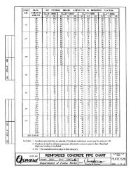
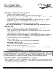
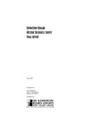
1.0 IntroductionThis Technical Report evaluates potential impacts on groundwater resources within aquifersunderlying the <strong>Oxnard</strong> Plain and Pleasant Valley areas (project area) resulting from the <strong>City</strong><strong>of</strong> <strong>Oxnard</strong> (<strong>City</strong>) Groundwater Recovery Enhancement and Treatment (GREAT) Program(proposed project). This evaluation was performed using the numerical groundwater flowmodel <strong>of</strong> the Santa Clara-Calleguas Basin that was developed by the United SatesGeological Survey (USGS) (USGS, 2003) in the 1990s and recently updated by theUnited Water Conservation District (UWCD) (UWCD, 2003).The <strong>City</strong> <strong>of</strong> <strong>Oxnard</strong> GREAT Program would be located in the area <strong>of</strong> western VenturaCounty known as the <strong>Oxnard</strong> Plain, which includes the urban and suburban areas <strong>of</strong> the<strong>City</strong> and adjacent communities (for example, Port Hueneme, Nyeland Acres, and El Rio). Italso includes agricultural areas <strong>of</strong> Ventura County, including the Pleasant Valley area. The<strong>Oxnard</strong> Plain is located approximately 60 miles northwest <strong>of</strong> downtown Los Angeles and35 miles south <strong>of</strong> Santa Barbara (see Figure 1-1).1.1 Project PurposeThe GREAT Program is a water resources project that would combine wastewater recyclingand reuse; groundwater injection, storage, and recovery; and groundwater desalination toprovide regional water supply solutions to water users within the <strong>Oxnard</strong> Plain andPleasant Valley areas. This technical report evaluates those elements <strong>of</strong> the GREAT Programthat will have a cumulative (year-to-year) regional effect on groundwater elevations withinthe aquifers underlying the <strong>Oxnard</strong> Plain and Pleasant Valley areas. Certain GREATProgram elements would create new sources <strong>of</strong> water supply by reusing <strong>City</strong> waste watertreatment plant effluent (WWTP) that is currently being treated to secondary standards anddischarged to a deep ocean outfall. Potential new water supplies would include thefollowing.• In Lieu Groundwater Recharge using Recycled Water. A portion <strong>of</strong> the currentsecondary effluent from the <strong>City</strong> WWTP would be treated to meet regulatory standardsfor direct nonpotable reuse (primarily irrigation) using a new tertiary treatment facility(TTF). This tertiary treated wastewater effluent would then be treated using a newadvanced water treatment facility (AWTF) to meet agricultural irrigation water qualitycriteria. This recycled water would be provided to growers on the south <strong>Oxnard</strong> Plainand Pleasant Valley in lieu <strong>of</strong> pumping groundwater for irrigation, where effects <strong>of</strong>current overdraft conditions are most severe. New pipeline conveyance systems wouldbe constructed to deliver the recycled water for irrigation. This would allowgroundwater pumping for irrigation to be reduced; and groundwater levels and theeffects <strong>of</strong> overdraft would recover using this in-lieu groundwater recharge technique.• Direct Injection Groundwater Recharge using Recycled Water. During winter monthswhen agricultural irrigation demand is low, a portion <strong>of</strong> the tertiary treated wastewatereffluent would be treated to meet regulatory standards using the new AWTF for directW112003002SCO LW1458.DOC/ 033390002 1
WATER RESOURCES TECHNICAL REPORT• Concentrate Collection System. A new concentrate 1 collection system would bedeveloped to serve the AWTF, the regional desalter, and various existing industrialbrine producers. The proposed concentrate collection system would collect the reverseosmosis (RO) concentrate produced by these facilities instead <strong>of</strong> allowing it to dischargeinto the existing <strong>City</strong> sewer system. This would make treatment <strong>of</strong> recycled waterproduced by the TTF and AWTF more efficient in meeting the reuse criteria foragricultural irrigation and direct aquifer injection.• Permeate Delivery System. A new permeate¹ distribution system would be developedto provide high quality water to industrial users. This would reduce the need to conductreverse osmosis (RO) treatment <strong>of</strong> <strong>City</strong> potable water, and also reduce discharges <strong>of</strong>concentrate to the current sanitary sewer system <strong>of</strong> the new concentrate collectionsystem.The GREAT Program, which would be implemented in two phases, is designed to provide areliable and affordable 2 source <strong>of</strong> high quality water. The objective <strong>of</strong> Phase 1 is to develop awater supply reliability and recycling program while maximizing use <strong>of</strong> current facilities tomeet current water supply deficits. Once Phase 1 is implemented and evaluated, theobjective <strong>of</strong> Phase 2 is to expand Phase 1 facilities and build new facilities to accommodatethe projected water supply needs that the <strong>City</strong> identifies in its 2020 general plan update.The ultimate size <strong>of</strong> the Phase 2 facilities is unknown, and will depend both on the level <strong>of</strong>planned growth as identified in the <strong>City</strong>’s general plan update, once completed, and on theresults <strong>of</strong> the Phase 1.1.2 Scope <strong>of</strong> WorkThe water resources technical study was conducted to assess the effects on groundwaterelevations from the (1) in-lieu groundwater recharge using recycled water for agriculturalirrigation, (2) direct injection groundwater recharge using recycled water, and(3) groundwater recovery for potable use. The technical study includes the followingmajor elements:• The environmental setting was established, including information on climate, surfacewater resources, and groundwater resources.• The existing supply and demand <strong>of</strong> potable water and water used for agriculturalirrigation was identified and reviewed.• The USGS numerical groundwater flow model <strong>of</strong> the Santa Clara-Calleguas Basin andthe UWCD update to that model were reviewed.1 In situations where brackish groundwater is treated with membrane filtration technology, two products are produced:“permeate” and “concentrate.” Permeate is produced through the removal <strong>of</strong> salts and is intended for consumption by varioususers. Concentrate is the portion that contains the concentrated salts and requires disposal. The terms “brine” and“concentrate” are used interchangeably for the purposes <strong>of</strong> discussion in this document.2 The GREAT Program would provide the <strong>City</strong> <strong>of</strong> <strong>Oxnard</strong> a more affordable source <strong>of</strong> high quality water in comparison to thecost <strong>of</strong> water (including penalties assessed) as a result <strong>of</strong> overpumping current <strong>City</strong> groundwater allocation or exceeding the<strong>City</strong>’s allocation <strong>of</strong> water from the State Water Project.W112003002SCO LW1458.DOC/ 033390002 3
WATER RESOURCES TECHNICAL REPORT• Detailed Phase 1 and Phase 2 scenarios for the GREAT Program were developed,simulated, and evaluated using the UWCD update to the USGS groundwater flowmodel.The USGS developed the groundwater flow model to better define the hydrogeologicframework <strong>of</strong> the regional groundwater flow system and to help analyze the majorproblems affecting water resources management <strong>of</strong> a typical coastal aquifer system, theSanta Clara-Calleguas Basin (USGS, 2003). The USGS calibrated the model to historicalsurface water and groundwater conditions for the period 1891 to 1993. UWCD updated themodel for a study related to the nature <strong>of</strong> recent inland saline (seawater) intrusion in thePleasant Valley groundwater basin and developed specific recommendations to controlor limit water quality problems associated with the migration and pumping <strong>of</strong> salinegroundwater. UWCD updated the model and extended the calibration period through 2000.It is the policy <strong>of</strong> UWCD that only UWCD have custody <strong>of</strong> the updated groundwater flowmodel and that only UWCD staff can run the model. Therefore, the actual simulations <strong>of</strong> thedetailed GREAT Program Phase 1 and Phase 2 scenarios were performed by Mr. SteveBachman, Ph.D., Groundwater Resources Manger <strong>of</strong> UWCD. CH2M HILL developed thedetailed Phase 1 and Phase 2 scenarios and evaluated the results <strong>of</strong> the model simulations incollaboration with Mr. Bachman. Mr. Bachman performed the model simulation work undercontract to the <strong>City</strong>.1.3 OrganizationThis technical report is organized into the following sections:• Section 1.0, Introduction. This section provides background, the purpose, and scope <strong>of</strong>work related to evaluating potential impacts to groundwater elevations within the<strong>Oxnard</strong> Plain hydrogeologic system as a result <strong>of</strong> implementing the GREAT Program.• Section 2.0, Environmental Setting. This section summarizes the environmental setting<strong>of</strong> the <strong>Oxnard</strong> Plain and vicinity as it relates to the GREAT Program, includingphysiography, climate, surface water resources, and groundwater resources.• Section 3.0, Water Supply and Demand. This section describes the currently availableregional water supplies and the current and projected water demands related to theGREAT Program.• Section 4.0, GREAT Program Project Description. This section provides a summary <strong>of</strong>the GREAT Program elements.• Section 5.0, Historical Groundwater Flow Modeling. This section summarizes theUSGS numerical groundwater flow model <strong>of</strong> the Santa Clara-Calleguas Basin and theUWCD update to that model.• Section 6.0, GREAT Program Groundwater Flow Modeling. This section provides themethodology and results <strong>of</strong> the model development and simulation <strong>of</strong> the detailedPhase 1 and Phase 2 scenarios for the GREAT Program.W112003002SCO LW1458.DOC/ 033390002 4
WATER RESOURCES TECHNICAL REPORT• Section 7.0, Summary and Conclusions. This section provides a summary <strong>of</strong> theevaluation <strong>of</strong> the groundwater elevation changes, and presents conclusions regardingimplementation <strong>of</strong> the GREAT Program.W112003002SCO LW1458.DOC/ 033390002 5
SANTA BARBARACOUNTYSanta BarbaraVENTURA COUNTY101VenturaLOS ANGELESCOUNTYPacific<strong>Oxnard</strong>Santa Monica Mountains101Los Angeles1OceanLegend<strong>City</strong>HighwayProject Area<strong>Oxnard</strong> PlainPleasant Valley AreaFigure 1-1Regional Project VicinitySanta Clara River<strong>City</strong> <strong>of</strong> <strong>Oxnard</strong> GREAT ProgramCounty BoundaryNote: Boundaries are approximate.0 4.5 9MilesGIS2 on 'Galt2'\<strong>Oxnard</strong>\Plots\Admin_Draft_EIR\GWTechReport\Fig01-1_8x11L.mxd User: TFaludy
2.0 Environmental SettingThis section describes the environmental setting <strong>of</strong> the <strong>Oxnard</strong> Plain and vicinity as it relatesto the GREAT Program, including physiography, climate, surface water resources, andgroundwater resources. The section utilizes information developed in previous studies,including those by the California Department <strong>of</strong> Water Resource (1958, 1965, 1967, 1971);California State Water Resources Control Board (1956); Freeman (1968); Izbicki (1996a,1996b); and Turner (1975), as summarized in the USGS report for the Simulation <strong>of</strong> Ground-Water/Surface-Water Flow in the Santa Clara-Calleguas Ground-Water Basin, VenturaCounty, California (USGS, 2003). Information was also obtained from United WaterConservation District (UWCD) in the form <strong>of</strong> direct communication (UWCD, 2003a) andreports prepared by UWCD (1998, 2001, 2003b).2.1 PhysiographyThe <strong>Oxnard</strong> Plain and Pleasant Valley are located along the coastal areas <strong>of</strong> the Santa ClaraRiver and Calleguas Creek watersheds, which together comprise the Santa Clara-CalleguasHydrologic Unit that is shown in Figure 2-1 together with the groundwater basins withinthis unit. Figure 2-1 is taken from the USGS modeling study (USGS, 2003) and shows thedetailed study area used by the USGS to simulate groundwater and surface water flow inthe Santa Clara-Calleguas Basin. The geographic features <strong>of</strong> this study area are shown inFigure 2-2, also taken from the USGS modeling study.Santa Clara-Calleguas Hydrologic Unit is located within the Transverse Mountain Ranges <strong>of</strong>Southern California. The Transverse Range physiographic province consists <strong>of</strong> an east-westtrending series <strong>of</strong> rugged, steep mountains and valleys in Southern California. The extent <strong>of</strong>this province includes the San Bernardino Mountains to the east and extends <strong>of</strong>fshore fromVentura County to include the Channel Islands to the west. The east-west structure <strong>of</strong> theTransverse Ranges is oblique to the normal northwest trend <strong>of</strong> coastal California mountainranges, and is due to intense north-south compression along the San Andreas Fault. TheTransverse Ranges are one <strong>of</strong> the most rapidly rising regions on earth.Rugged mountainous terrain covers most <strong>of</strong> the northern Ventura County while broaderalluvial valleys and lower rolling topography occur in the southern portions <strong>of</strong> the County.The mountainous areas to the north rise to elevations in excess <strong>of</strong> 6,000 feet above mean sealevel. Ground surface elevations vary from about 60 to 150 feet above mean sea level on the<strong>Oxnard</strong> Plain and from about 15 to 250 feet above mean sea level in Pleasant Valley. TheSanta Clara River watershed drains most <strong>of</strong> northern Ventura County and northwesternLos Angeles County, and Calleguas Creek drains most <strong>of</strong> southern Ventura County.Together, the Santa Clara-Calleguas Hydrologic Unit has a total drainage area <strong>of</strong>approximately 2,000 square miles. Almost 90 percent <strong>of</strong> this drainage area is characterizedby rugged topography, while the remainder consists <strong>of</strong> flatter valley floor and coastal plaintopography.W112003002SCO LW1458.DOC/ 033390002 6
WATER RESOURCES TECHNICAL REPORT2.2 Water Resources Management2.2.1 United Water Conservation DistrictUWCD manages the surface water and groundwater resources over an area encompassingabout 330 square miles covering the downstream portion <strong>of</strong> the Santa Clara River valleyand the <strong>Oxnard</strong> Plain area. The UWCD service boundary, groundwater basins within theSanta Clara-Calleguas Basin, and major recharge and conveyance facilities within theUWCD service boundary are shown in Figure 2-3. The UWCD boundary encompasses thearea that would be affected by the GREAT Program. UWCD, originally formed by locallandowners in 1927 as the Santa Clara River Water Conservation District, was created in1950 to address groundwater overdraft issues. UWCD administers a basin managementprogram for the Santa Clara Valley and <strong>Oxnard</strong> Plain, utilizing surface flow from theSanta Clara River and its tributaries for replenishment <strong>of</strong> groundwater. UWCD facilities,which are further described in Section 3.0, include Santa Felicia Dam and Lake PiruRecreation Area; Piru, Saticoy, and El Rio Spreading Grounds; Pleasant Valley pipeline andreservoirs; <strong>Oxnard</strong>-Hueneme (O-H) pipeline, pumping plant and pumping-trough pipeline;and other facilities.2.2.2 Fox Canyon Groundwater Management AgencyGroundwater resources within the <strong>Oxnard</strong> Plain, Pleasant Valley, Las Posas Valley, andSanta Rosa Valley are managed by the FCGMA, which was created in 1982 to preservegroundwater resources for water users in all areas overlying the Fox Canyon aquifer zone.The FCGMA has jurisdiction over groundwater resources located beneath all land thatoverlies the Fox Canyon Aquifer, which encompasses approximately 185 square miles. TheFCGMA manages groundwater resources through ordinances and does not own any capitalfacilities. Ordinance No. 5, adopted in 1990, is the most significant ordinance adopted by theFCGMA. Ordinance No. 5 addresses groundwater overdraft by requiring reductions ingroundwater extractions via scheduled 5 percent reductions beginning in 1990 every 5 yearsthat will total 25 percent by 2010. The objective is to reduce extractions to a "safe yield" levelby 2010. The reductions are based on actual pumping records during the 5-year “base”period from 1985 through 1989. Funding for FCGMA operations is based on extractioncharges by pumpers within the agency boundary. Ordinance No. 5 has been superceded byOrdinance No. 8 adopted in 2002.2.2.3 United States Geological SurveyThe USGS, in partnership with the FCGMA, other water purveyors on the <strong>Oxnard</strong> Plain,and numerous other well owners, has performed several studies to assist with management<strong>of</strong> groundwater resources within the Santa Clara-Calleguas Hydrologic Unit. These studiesare part <strong>of</strong> the ongoing Southern California Regional Aquifer System Analysis (RASA)Program. The purpose <strong>of</strong> the RASA Program has been to analyze the major issues affectinggroundwater use in Southern California, including groundwater overdraft, stream-flowdepletion, subsidence, seawater intrusion, and groundwater contamination. The SantaClara-Calleguas Basin was selected as the typical “coastal” groundwater basin for thisstudy. In 1984 to 1985, the USGS designed and installed a series <strong>of</strong> clustered monitoringwells along the <strong>Oxnard</strong> Plain to provide water level and water quality data specific to eachW112003002SCO LW1458.DOC/ 033390002 7
WATER RESOURCES TECHNICAL REPORTindividual aquifer layer or zone, and allow evaluation <strong>of</strong> the seawater intrusion problem. Inthe 1990s, the USGS constructed 32 multiple-well monitoring sites in the western part <strong>of</strong> theSanta Clara River Valley and monitored 29 existing wells to gather data on geology, waterlevels, groundwater quality, and aquifer properties at different depths. In 1996, the USGSbegan the computer modeling study <strong>of</strong> the Santa Clara-Calleguas Basin. The results <strong>of</strong> theongoing RASA program in Ventura County, which have been important to understandingthe groundwater resources <strong>of</strong> the Santa Clara-Calleguas Hydrologic Unit, are documentedin a number <strong>of</strong> USGS reports.2.3 ClimateCoastal Southern California and Ventura County have a Mediterranean climate regimecharacterized by a long, dry, warm summer season followed by a shorter wet winter periodaccompanied by cooler temperatures. Average monthly precipitation and average monthlytemperatures are shown in Figure 2-4 for three meteorological weather stations withincreasing distance from the ocean and elevation: <strong>Oxnard</strong> (046569), Santa Paula (047957),and Ojai (046399).2.3.1 TemperatureTemperature extremes generally increase with elevation and distance from the ocean(Figure 2-4). Average high temperatures for <strong>Oxnard</strong>, Santa Paula, and Ojai are 70.1, 74.6,and 77.7 degrees Fahrenheit (°F) and average low temperatures are 51.0, 47.8, and 45.8°F,respectively. The growing season, or lapse <strong>of</strong> time between killing frosts, is long, andgenerally decreases with elevation and distance from the ocean. Certain areas produce asmany as three crops per year because killing frost on the coastal plain is rare.2.3.2 PrecipitationMost precipitation occurs in the winter months during a few major storms. Approximately85 percent <strong>of</strong> precipitation occurs between November and April and generally increaseswith increasing ground surface elevation (Figure 2-4). Average annual precipitation for<strong>Oxnard</strong>, Santa Paula, and Ojai are 14.77, 17.84, and 21.18 inches respectively. Precipitationexceeds 25 inches in the higher mountainous areas where some snowfall occurs in mostyears.The 114-year annual precipitation record for Santa Paula is shown in Figure 2-5. This recordprovides annual precipitation by water year from 1890 through 2003, the 114-year averageand median precipitation, and the cumulative departure from the 114-year averageprecipitation. These data are collected and maintained by UWCD at gauge No. 245. The114-year average and median precipitation values are 17.38 and 14.89 inches, respectively.Daily evaporation measurements are recorded from a standard Weather Bureau Class A panat the UWCD El Rio spreading grounds. The average measured evaporation rate is59.31 inches, approximately 3.5 times the average precipitation.Precipitation records show shorter- and longer-term cyclic patterns <strong>of</strong> dry periods and wetcycles. The shorter-term cycle is known as the El Niño/Southern Oscillation (ENSO) and thelonger-term cycle is known as the Pacific Decadal Oscillation (PDO). Multi-year dry periodsare indicated in Figure 2-5 by declining cumulative departure values, and correspondingW112003002SCO LW1458.DOC/ 033390002 8
WATER RESOURCES TECHNICAL REPORTmulti-year wet periods are indicated by rising values. Figure 2-5 indicates four longer-termdry/wet cycles through 1998:Historical Dry and Wet PeriodsDry PeriodWet PeriodCycle Period Years Period Years1 1890 - 1904 15 1904 - 1918 152 1918 - 1934 17 1934 - 1944 113 1944 - 1977 34 1977 - 1983 74 1983 - 1991 9 1991 - 1998 8ENSO refers to a seesaw shift in surface air pressure at Darwin, Australia, and theSouth Pacific Island <strong>of</strong> Tahiti. When the pressure is high at Darwin, it is low at Tahiti andvice versa. El Niño, and its sister event-La Niña-are the extreme phases <strong>of</strong> the southernoscillation, with El Niño referring to a warming <strong>of</strong> the eastern tropical Pacific, and La Niñaas cooling. El Niño brings heavy rains and blustery storms to Southern California, whileLa Niña brings dry conditions. El Niño recurs irregularly, from 2 years to a decade; and notwo events are exactly alike. During the past 40 years, nine El Niño events have affected thewestern coasts <strong>of</strong> North and South America. Most <strong>of</strong> them have raised water temperaturesalong 5,000 miles <strong>of</strong> coast. The weaker events raised sea temperatures only a few degreesFahrenheit and caused mild changes in weather. But the strong ones, like the El Niño <strong>of</strong>1982-83, left a climatic imprint that was global in extent.The PDO is a long-lived El Niño-like pattern <strong>of</strong> Pacific climate variability. While the twoclimate oscillations have similar spatial climate fingerprints, they have very differentbehavior in time. Two main characteristics distinguish PDO from ENSO. First, 20th centuryPDO "events" persisted for 20 to-30 years, while typical ENSO events persisted for 6 to18 months. Second, the climatic fingerprints <strong>of</strong> the PDO are most visible in the NorthPacific/North American sector; while secondary signatures exist in the tropics , the oppositeis true for ENSO. Several studies find evidence for just two full PDO cycles in the pastcentury:PDO Regime Duration Period“Cool” or 35 years 1890-1924"Warm” 22 years 1925-1946“Cool” 30 years 1947-1976"Warm" -- 1977 through (at least) the mid-1990'sCauses <strong>of</strong> the PDO are currently not well understood. As described below, groundwaterlevels are correlated to these longer-term climatic patterns. In general, groundwater levelsincrease with wetter climatic periods representing increased recharge and reducedpumping, while they decrease with drier climatic periods representing decreased rechargeW112003002SCO LW1458.DOC/ 033390002 9
WATER RESOURCES TECHNICAL REPORTand increased pumping. Because these longer-term climatic patterns are not wellunderstood, the prediction <strong>of</strong> future groundwater levels also results in uncertainty.2.4 Surface WaterSurface water in the Santa Clara-Calleguas Hydrologic Unit consists <strong>of</strong> stream flow andremnant wetlands from the extensive estuarine wetlands that existed on the <strong>Oxnard</strong> Plainin the mid-1800s before development. Run<strong>of</strong>f from precipitation in the upland areas is thepredominant source <strong>of</strong> natural stream flow. Discharge <strong>of</strong> treated wastewater effluent,which began in the late 1930s, provides an additional source <strong>of</strong> water to stream flow.Stream flow has historically been diverted for agriculture for enhanced artificial recharge<strong>of</strong> the groundwater system. Surface water has been imported from outside theSanta Clara-Calleguas Unit since the 1950s as a source <strong>of</strong> potable surface water toVentura County and the <strong>Oxnard</strong> Plain.2.4.1 Stream FlowAs described above, the Santa Clara River and Calleguas Creek are the main watershedsthat drain Ventura County (Figures 2-1 and 2-2). The Santa Clara River drains the northernand eastern portions <strong>of</strong> the Santa Clara-Calleguas Hydrologic Unit, and Calleguas Creekdrains and southern portions <strong>of</strong> this unit. The Santa Clara River, which drains theheadwaters <strong>of</strong> the mountainous areas <strong>of</strong> northern Ventura County and northwesternLos Angeles County, is the largest river system in Southern California that remains in arelatively natural state. Its major tributaries are Piru, Hopper, Pole, Sespe, Santa Paula, andEllsworth Creeks. Calleguas Creek drains a predominantly agricultural area on the <strong>Oxnard</strong>Plain and empties into Mugu Lagoon, one <strong>of</strong> the Southern California few remaining largewetlands <strong>of</strong> Southern California. Its major tributaries are Conejo Creek and ArroyoSimi/Arroyo Las Posas. Revolon Slough is a smaller watershed that drains coastal areas onthe <strong>Oxnard</strong> Plain between the Santa Clara and Calleguas Creek watersheds. Its majortributaries are Arroyo Hondo and Beardsley Wash.Hydrographs for the Santa Clara River, Arroyo Simi, and Conejo Creek are provided inFigure 2-6 at the following locations:• Santa Clara River at County Line and Santa Clara River near Piru• Arroyo Simi near Simi and Arroyo Simi at Madera Road Bridge• Conejo Creek above Highway 101Stream flow gauging stations were first established on Arroyo Simi in 1934 and on ConejoCreek in the 1970s. Continuous gauging <strong>of</strong> stream flow at downstream sites began atMontalvo on the Santa Clara River in 1955, on Calleguas Creek above U.S. Highway 101 in1971, and at Camarillo in 1968. Most natural stream flow occurs from December throughApril in the winter and spring as flood flow. Construction <strong>of</strong> reservoirs and discharge <strong>of</strong>shallow groundwater (for dewatering) and treated wastewater effluent have contributed toregulated flow and modification <strong>of</strong> river systems in the basin. The Santa Clara River, PiruCreek, Arroyo Simi, and Conejo Creek all have components <strong>of</strong> regulated flow, whichincrease the mean flow and decrease the number <strong>of</strong> days with no flow.W112003002SCO LW1458.DOC/ 033390002 10
WATER RESOURCES TECHNICAL REPORT2.4.2 Imported Surface WaterThe Department <strong>of</strong> Water Resources transports surface water, largely from the Feather andSacramento Rivers in northern California, through the Sacramento-San Joaquin Delta toSouthern California via the California Aqueduct, or State Water Project. In SouthernCalifornia, the aqueduct splits into east and west branches terminating at Perris and CastaicReservoirs, respectively. Water from the State Water Project is imported to users within theSanta Clara-Calleguas Basin as follows:• UWCD Conservation District. UWCD imports water from northern California toPyramid Lake and Lake Piru where it is periodically released into Piru Creek and theSanta Clara River.• Calleguas Municipal Water District. CMWD imports water from northern Californiamostly for municipal supplies.• Los Angeles County Area. Water from northern California is imported by Castaic LakeWater Agency located in the headwaters <strong>of</strong> the Santa Clara River watershed.This imported water supplements the local supplies and is ultimately a source <strong>of</strong> recharge tothe surface water and groundwater system <strong>of</strong> the region, either directly from direct releasesor indirectly from wastewater effluent and irrigation return flows.2.4.3 Water Conservation FacilitiesUWCD operates several water conservation facilities within the Santa Clara-CalleguasHydrologic Unit (Figure 2-3). These include the following surface water facilities, which arefurther described in Section 3.0.• Santa Felicia Dam. Santa Felicia Dam (1955) captures and stores winter run<strong>of</strong>f from PiruCreek for later release in controlled amounts to replenish the Piru, Fillmore, Santa Paula,and <strong>Oxnard</strong> Plain groundwater basins, and supply surface water for irrigation.• Freeman Diversion. The Freeman Diversion (1991), located near Saticoy, diverts surfacewater from the Santa Clara River for enhanced groundwater recharge at the spreadinggrounds in the <strong>Oxnard</strong> Forebay and distribution to the southern <strong>Oxnard</strong> Plain foragricultural irrigation.• Spreading Grounds and Wellfields. Surface water from the Freeman diversion isconveyed into spreading grounds to enhance groundwater recharge in the <strong>Oxnard</strong>Forebay area, which is the most important source <strong>of</strong> regional recharge to the <strong>Oxnard</strong>Plain. These spreading grounds consist <strong>of</strong> the Saticoy Recharge ponds, the Noble Pit,and El Rio recharge ponds. Wellfields at the Saticoy and El Rio spreading groundsrecover groundwater for potable and agricultural use.• <strong>Oxnard</strong>-Hueneme Delivery System. The <strong>Oxnard</strong>-Hueneme (O-H) pipeline (1954)moves municipal groundwater extraction away from coastal areas subject to seawaterintrusion. The O-H system consists <strong>of</strong> wells located at the El Rio spreading grounds,three wells along Rose Avenue, a water treatment plant, booster plant, and 12 miles <strong>of</strong>distribution pipeline. The O-H pipeline delivers potable water to wholesale customerson the <strong>Oxnard</strong> Plain.W112003002SCO LW1458.DOC/ 033390002 11
WATER RESOURCES TECHNICAL REPORT• Pumping-trough Pipeline. The pumping-trough pipeline (PTP) (1986) conveys divertedriver water to agricultural pampers on the <strong>Oxnard</strong> Plain to <strong>of</strong>fset pumping <strong>of</strong> wells inthis area.• Pleasant Valley Pipeline. The Pleasant Valley Pipeline (1958) supplies surface waterfrom the UWCD diversion to agricultural users in Pleasant Valley to <strong>of</strong>fset pumping <strong>of</strong>wells in this area. The Pleasant Valley pipeline terminates at Pleasant Valley Reservoir,owned by the Pleasant Valley County Water District.2.4.4 Treated Wastewater EffluentMost wastewater effluent in the Santa Clara-Calleguas Hydrologic Unit is treated anddischarged directly to the Pacific Ocean, the Santa Clara River, Calleguas Creek, andConejo Creek. Some wastewater effluent is also discharged to percolation ponds for directinfiltration and reused for irrigation. Municipal treatment plants contributing to recharge<strong>of</strong> the regional surface water and groundwater system include the following:• <strong>City</strong> <strong>of</strong> Fillmore• <strong>City</strong> <strong>of</strong> Santa Paula• Saticoy Sanitation District• <strong>City</strong> <strong>of</strong> Moorpark (Ventura County No. 19)• <strong>City</strong> <strong>of</strong> Thousand Oaks• Camarillo Sanitation District• CamrosaReuse <strong>of</strong> treated wastewater effluent is beginning to be implemented in Ventura County.One current project, known as the Conejo Creek Diversion Project, is being implemented byCalleguas Municipal Water District (CMWD), which involves the delivery <strong>of</strong> tertiary treatedwastewater from the <strong>City</strong> <strong>of</strong> Thousand Oaks and water from the Conejo Creek to irrigationwater users in the service areas <strong>of</strong> Camrosa Water District and Pleasant Valley CountyWater District. This water would otherwise flow to the ocean and be a lost resource. Thisproject has been in operation since 2002 and is further described in Section 3.0.As further described in Section 3.0, the <strong>City</strong> <strong>of</strong> <strong>Oxnard</strong> currently discharges effluent from itswastewater treatment plant (treated to secondary standards) directly to a permitted deepocean outfall. This discharge currently does not contribute to the benefit <strong>of</strong> the waterresources <strong>of</strong> the region. Reclaiming this lost resource is the foundation to the GREATProgram that would allow wastewater to be treated to higher standards (tertiary andadvanced treatment) for reuse, primarily for agricultural irrigation and groundwaterrecharge on the southern <strong>Oxnard</strong> Plain, where overdraft conditions and the effects <strong>of</strong> thatoverdraft are most severe.2.4.5 Mugu Lagoon and Ormond Beach WetlandsMugu Lagoon and South Ormond Beach is one <strong>of</strong> the few remaining pieces <strong>of</strong> a once vastwetland. Mugu Lagoon is the most extensive wetland in the Region and supports a richdiversity <strong>of</strong> fish and wildlife that once inhabited much <strong>of</strong> Southern California’s coastalareas. Historical maps <strong>of</strong> Ormond Beach indicate that in 1855 it was an extensive system <strong>of</strong>estuarine wetlands that extended over an area from Mugu Lagoon on the south to north <strong>of</strong>Point Hueneme on the north end. Since that time, the wetlands complex has declineddrastically due to the damming <strong>of</strong> upstream creeks, diversion <strong>of</strong> surface waters foragricultural and industrial development, and infrastructure controls placed on the tidal flowW112003002SCO LW1458.DOC/ 033390002 12
WATER RESOURCES TECHNICAL REPORT<strong>of</strong> Mugu Lagoon to support an adjacent Naval Air Station. Efforts are currently underwayby the California Coastal Conservancy and other stakeholders to restore a portion <strong>of</strong> theremnant wetlands to their former extent and quality.2.4.6 Duck ClubThe Ventura County Game Preserve <strong>of</strong>ten referred to as "The Duck Club" is a privatehunting club that is located along the southern coastal areas <strong>of</strong> the <strong>Oxnard</strong> Plain. The DuckClub maintains several hundred acres <strong>of</strong> wetlands habitat north <strong>of</strong> Mugu Lagoon within thehistorical extent <strong>of</strong> the system <strong>of</strong> estuarine wetlands that extended over an area from MuguLagoon on the south to Point Hueneme on the north.2.4.7 Industrial and Agricultural DrainsIndustrial and agricultural drains exist on <strong>Oxnard</strong> Plain that convey poor quality water tocoastal areas that help prevent degradation <strong>of</strong> shallow groundwater. Industrial drainsinclude the <strong>Oxnard</strong> Industrial Drain, J Street Drain, and the Rice Road Drain. Agriculturaldrains are located across the <strong>Oxnard</strong> Plain and Pleasant Valley areas.2.4.8 Coastal Waters and the Pacific OceanThe Pacific Ocean is the ultimate receiving water body for surface waters from the SantaClara Hydrologic Unit. Coastal waters <strong>of</strong> the <strong>Oxnard</strong> Plain area include estuaries, lagoons,harbors, beaches, and ocean waters. Estuaries include coastal lagoons such as MuguLagoon, McGrath Lake, and the mouth <strong>of</strong> the Santa Clara River. Harbors include the deepdraftcommercial harbor at Port Hueneme and Channel Islands Harbor. Recreationalbeaches occur along large stretches <strong>of</strong> these coastal waters.2.5 Geology2.5.1 TectonicsThe <strong>Oxnard</strong> Plain is located in the Ventura Basin in the western portion <strong>of</strong> the TransverseRanges. The tectonics <strong>of</strong> the western Transverse Ranges is characterized by clockwiserotation and crustal shortening, caused by convergence <strong>of</strong> the North American and Pacificplates along a northwest-trending segment <strong>of</strong> San Andreas Fault. Folding and displacementon thrust and reverse faults accommodate this compressional strain, resulting in regionaluplift, mountain formation, basin formation, and seismicity.The Ventura Basin is a deep, structural trough filled with approximately 35,000 feet <strong>of</strong>Cretaceous through Cenozoic sedimentary and volcanic rocks (Dibblee, 1982). The basinforms the Santa Clara River Valley, <strong>Oxnard</strong> Plain, and Santa Barbara Channel <strong>of</strong>fshore. Themain synclinal axis <strong>of</strong> the basin coincides roughly with the course <strong>of</strong> the Santa Clara River.A series <strong>of</strong> younger (Quaternary) folds and faults trend east-west across the basin,subparallel to the main synclinal axis. The flanks <strong>of</strong> the basin were uplifted alongeast-trending, left-lateral reverse fault systems, exposing the older sedimentary and volcanicrocks that form the Santa Ynez Mountains and the Santa Monica Mountains/ChannelIslands; these ranges form the northern and southern boundaries <strong>of</strong> the basin, respectively(Dibblee, 1982).W112003002SCO LW1458.DOC/ 033390002 13
WATER RESOURCES TECHNICAL REPORT2.5.2 StratigraphyThe lithologic units in the Santa Clara–Calleguas Basin can be grouped into two generalcategories: (1) upper Cretaceous and Tertiary bedrock and (2) Quaternary unconsolidateddeposits. The outcrop pattern <strong>of</strong> the lithologic units is shown in Figure 2-7 and theirstratigraphic relationships are shown in Figure 2-8. These two figures are modified from theUSGS groundwater modeling study (USGS, 2003). Figure 2-8 relates the lithologic units andformations to their associated aquifer units, which are further described below. A summary<strong>of</strong> the stratigraphic analysis by the USGS is provided below.Upper Cretaceous and Tertiary BedrockThe upper Cretaceous and Tertiary consolidated rocks include sedimentary, volcanic,igneous, and metamorphic rocks, which are virtually nonwater bearing and form the base <strong>of</strong>the Santa Clara-Calleguas Basin. Although these rocks are not an important source <strong>of</strong>groundwater, the erosion and subsequent deposition <strong>of</strong> these rocks are sources <strong>of</strong>unconsolidated deposits that form the Santa Clara-Calleguas groundwater basin. Theconsolidated Tertiary sedimentary rocks underlie most <strong>of</strong> the groundwater basin andcompose the surrounding mountains and hills. These rocks are predominantly marine inorigin and are nearly impermeable.Quaternary Unconsolidated DepositsThe Quaternary unconsolidated deposits consist <strong>of</strong> the Pico Formation, Santa BarbaraFormation, the Las Posas Sand, the San Pedro Formation, and the Saugus Formation. All are<strong>of</strong> the Pleistocene epoch and are unnamed, unconsolidated alluvial and fluvial deposits <strong>of</strong>the Pleistocene to Holocene epoch. As further described below, these unconsolidatedQuaternary deposits are grouped together into an upper aquifer system (UAS) and loweraquifer system (LAS) across the Santa Clara-Calleguas Basin.Pleistocene Epoch. During the Pleistocene epoch, major changes in sea level resulted incycles <strong>of</strong> erosion and deposition. The sequence <strong>of</strong> deposits above these erosionalunconformities typically starts with a basal conglomerate that is laterally extensive,relatively more permeable than the underlying deposits, and a potential major source <strong>of</strong>water to wells perforated in these deposits. These coarse-grained layers <strong>of</strong> fluvial and beachdeposits are interbedded with extensive fine-grained layers.The Santa Barbara Formation overlies consolidated Tertiary rocks in most <strong>of</strong> thegroundwater basin and consists <strong>of</strong> marine sandstone, siltstone, mudstone, and shale. Thethickness and lithology <strong>of</strong> the formation varies considerably throughout the basin. It isthickest, more than 5,000 feet, in the Ventura area. The formation is <strong>of</strong> low permeability andgenerally contains water <strong>of</strong> poor quality throughout most <strong>of</strong> the basin.The lower part <strong>of</strong> the San Pedro Formation consists <strong>of</strong> shallow marine sand and gravel beds.These deposits reach a maximum thickness <strong>of</strong> more than 2,000 feet in the Santa Clara RiverValley near Ventura and consist <strong>of</strong> a series <strong>of</strong> relatively uniform fine-grained sand layers100 to 300 feet thick separated by silt and clay layers 10 to 20 feet thick.The upper part <strong>of</strong> the San Pedro Formation consists <strong>of</strong> lenticular layers <strong>of</strong> sand, gravel, silt,and clay <strong>of</strong> marine and continental origin. The continental fluvial silt, sand, and graveldeposits within the upper part <strong>of</strong> the San Pedro Formation are referred to as the SaugusW112003002SCO LW1458.DOC/ 033390002 14
WATER RESOURCES TECHNICAL REPORTFormation. These deposits reach a maximum thickness <strong>of</strong> more than 5,000 feet in the Piruarea <strong>of</strong> the Santa Clara River Valley. The sand and gravel layers range from 10 to 100 feetthick and are separated by silt and clay layers that are generally 10 to 20 feet thick.Late Pleistocene and Holocene Epoch. The Late Pleistocene and Holocene deposits areunnamed and consist <strong>of</strong> relatively flat-lying marine and continental unconsolidateddeposits. These deposits are derived from local sources from the Santa Clara River andCalleguas Creek, and were deposited unconformably on the older unconsolidated depositsand contain basal conglomerates that are laterally extensive and produce substantialgroundwater supplies.Alluvial and fluvial sand and gravel deposits with interbedded fine-grained deposits <strong>of</strong> theHolocene epoch unconformably overlie the Late Pleistocene deposits. Basal deposits <strong>of</strong> theHolocene epoch are relatively more permeable than underlying deposits, and are potentialmajor sources <strong>of</strong> water to wells completed in the saturated parts <strong>of</strong> these deposits.Interbedded sand layers occur within the fine-grained deposits. On the <strong>Oxnard</strong> Plain, thebasal zones are overlain with fine-grained deposits <strong>of</strong> low permeability, which createshallow, perched groundwater <strong>of</strong> poor quality that is not considered to be part <strong>of</strong> theregional upper aquifer and lower aquifer system.2.6 GroundwaterGroundwater is the main source <strong>of</strong> water in the Santa Clara-Calleguas hydrologic basin. Theonshore part <strong>of</strong> the alluvial groundwater basins covers approximately 310 square miles inVentura County. The lithologic units <strong>of</strong> the aquifers comprising the onshore alluvialgroundwater basins extend <strong>of</strong>fshore covering an additional area <strong>of</strong> approximately193 square miles <strong>of</strong> continental shelf. The groundwater basins within the Santa Clara-Calleguas Basin are shown in Figure 2-1 from the USGS modeling study and thegroundwater basins within the UWCD service boundary are shown in Figure 2-3.Groundwater basins along the Santa Clara River Valley, from upstream to downstream,include the Piru basin, Fillmore basin, and the Santa Paula basin. Groundwater basins alongthe Coastal areas, from north to south, include the Mound, <strong>Oxnard</strong> Plain Forebay, and<strong>Oxnard</strong> Plain. Basins further inland from the coastal areas include the Las Posas basin, SantaRosa Valley basin, and Pleasant Valley basin. Figure 2-1 also provides ocean bottombathymetry, which shows the continental shelf that extends several miles <strong>of</strong>fshore and isbisected by the Hueneme submarine canyon near Port Hueneme and by the Mugusubmarine canyon near Pt. Mugu. These submarine canyons bisect the aquifers on the<strong>Oxnard</strong> Plain that extend <strong>of</strong>fshore making them vulnerable to seawater intrusion.Water wells were first drilled in Ventura County using machinery instead <strong>of</strong> hand laborbeginning in the 1880s. A steady increase in groundwater demand for farming and urbanuses since the late 1800s has resulted in groundwater overdraft conditions. In general terms,groundwater overdraft is the withdrawal <strong>of</strong> potable water from an aquifer system in excess<strong>of</strong> replenishment from natural and artificial recharge. This overdraft has resulted in thefollowing conditions within the aquifers <strong>of</strong> the <strong>Oxnard</strong> Plain and Pleasant Valley:• Groundwater storage reductions• Declining groundwater levels to below sea levelW112003002SCO LW1458.DOC/ 033390002 15
WATER RESOURCES TECHNICAL REPORT• Water quality degradation, including seawater intrusion• Ground subsidenceThe hydrogeology and groundwater resources are discussed below, with an emphasis onthe <strong>Oxnard</strong> Plain Forebay, <strong>Oxnard</strong> Plain, and Pleasant Valley basins, which are those basinsthat will be affected by the GREAT Program. Groundwater levels and quality are activelymonitored by the UWCD and USGS, in addition to other entities, as part <strong>of</strong> watermanagement activities. These data are critical to understanding the historical and currentoverdraft conditions. The locations <strong>of</strong> wells from which monitoring data are currentlycollected are summarized on the four maps shown in Figure 2-9, which were providedby UWCD.2.6.1 Aquifer UnitsThe Santa Clara-Calleguas Basin consists <strong>of</strong> multiple aquifers that are grouped into a UASand an LAS. These aquifers contain gravel and sand materials that were deposited along theancestral Santa Clara River, within alluvial fans along the flanks <strong>of</strong> mountains, and withincoastal plain/delta complex at the terminus <strong>of</strong> the ancestral Santa Clara River. The surfacegeology <strong>of</strong> the outcropping stratigraphic units that comprise the UAS, LAS, and deeperbedrock are shown in Figure 2-7, and the stratigraphy <strong>of</strong> the materials comprising theseunits is shown in Figure 2-8.The UAS consists <strong>of</strong> the Shallow, <strong>Oxnard</strong>, and Mugu aquifers, which include theunconsolidated deposits <strong>of</strong> the late Pleistocene and Holocene epochs. The Shallow Aquiferis also referred to as the Semi-Perched Aquifer. The UAS is separated by an unconformityfrom the LAS. The LAS consists <strong>of</strong> the upper and lower Hueneme, Fox Canyon, and GrimesCanyon aquifers, which include the unconsolidated deposits <strong>of</strong> the Pliocene and Pleistoceneepochs. The sediments <strong>of</strong> the LAS extend to about 1,600 feet below sea level in the <strong>Oxnard</strong>Plain. All <strong>of</strong> these aquifers extend <strong>of</strong>fshore within the continental shelf. The onshore part <strong>of</strong>the <strong>Oxnard</strong> Plain is subdivided into a confined region and an unconfined region. Theconfined region includes the <strong>Oxnard</strong> Plain Forebay and the northeastern part <strong>of</strong> the <strong>Oxnard</strong>Plain where the Semi-Perched Aquifer is absent. The sediments <strong>of</strong> the UAS and LAS areunderlain by older bedrock <strong>of</strong> upper Cretaceous and Tertiary age that is consolidated andmostly nonwater bearing.These aquifer systems are bounded below and along mountain fronts by consolidatedbedrock that forms a relatively impermeable boundary to groundwater flow. Numerousfaults act as low permeability boundaries to groundwater flow. The aquifer systems extend<strong>of</strong>fshore where they crop out along the edge <strong>of</strong> the submarine shelf within the coastalsubmarine canyons. Submarine canyons have dissected these regional aquifers, providing ahydraulic connection to the ocean through the submarine outcrops <strong>of</strong> the aquifer system.Regionally, groundwater flows from the inland areas toward the ocean, east to west.Locally, however, overdraft has resulted in groundwater elevations below sea level thathave resulted in flow from the ocean inland (landward flow), which has resulted inseawater intrusion in both UAS and LAS.Three generally east-west cross sections from the USGS groundwater modeling report, B-B’,C-C’, and D-D’, are provided in Figure 2-10 to the subsurface geology <strong>of</strong> these units in the<strong>Oxnard</strong> Plain and Pleasant Valley Areas. The cross sections are aligned with the coastline.W112003002SCO LW1458.DOC/ 033390002 16
WATER RESOURCES TECHNICAL REPORTThe northern cross section, B-B’, runs through the northeastern tip <strong>of</strong> the <strong>Oxnard</strong> Plain,through the <strong>Oxnard</strong> Forebay and northwestern <strong>Oxnard</strong> Plain, and out to the edge <strong>of</strong> thecontinental shelf. The middle cross section, C-C’, runs through the central portion <strong>of</strong> the<strong>Oxnard</strong> Plain and terminates at Hueneme Canyon. The southern cross section, D-D’, runsthrough Pleasant Valley, through the southern <strong>Oxnard</strong> Plain, and terminates at MuguCanyon.Clay layers, as schematically shown in the DWR 1976 cross section in Figure 2-11, separatethe individual aquifers within the UAS and LAS. As further described below, the UAS isunconfined in the <strong>Oxnard</strong> Forebay area making this an important recharge area on the<strong>Oxnard</strong> Plain. In addition, the clay layers separating the aquifer units <strong>of</strong> the UAS from theLAS are also notably less significant in this area, making recharge to the LAS possible. Claylayers separate the UAS from the LAS across the remainder <strong>of</strong> the <strong>Oxnard</strong> Plain andremaining Santa Clara-Calleguas Basin, making natural recharge to the LAS slow.The Department <strong>of</strong> Water Resources (DWR) 1976 cross section also shows seawaterintrusion extending inland from the outer continental shelf into the onshore portion <strong>of</strong> the<strong>Oxnard</strong> Aquifer <strong>of</strong> the UAS. This is a useful schematic diagram to illustrate seawaterintrusion; however, two items are noted as follows. First, as further described below,seawater intrusion also exists within the other aquifers <strong>of</strong> the UAS and LAS. Second,although seawater intrusion has likely occurred into the <strong>of</strong>fshore continental shelf as shown,the inland seawater intrusion affecting coastal groundwater likely resulted from thesubmarine canyons short-circuiting the travel distance from the ocean to inland areas.The individual aquifer systems are discussed below, from shallowest to deepest.Upper Aquifer SystemShallow Aquifer or “Semi-Perched” Aquifer. The shallow aquifer beneath the <strong>Oxnard</strong> Plainand Pleasant Valley basins consists <strong>of</strong> fine to medium-grained sand with interbedded claylayers and is referred to as the “semi-perched aquifer.” Clay layers separate the shallowaquifer from the underlying <strong>Oxnard</strong> aquifer. Water quality is poor throughout most to the<strong>Oxnard</strong> Plain and Pleasant Valley sub-basins in this unit; consequently, few wells areperforated in this interval. The shallow aquifer extends to a depth <strong>of</strong> approximately 100 feetbelow ground surface (bgs).<strong>Oxnard</strong> Aquifer. The <strong>Oxnard</strong> aquifer lies at the base <strong>of</strong> the Holocene deposits, which consists<strong>of</strong> sand and gravel deposited by the ancestral Santa Clara River and Calleguas Creeksystem. The base <strong>of</strong> the aquifer ranges from about 150 to 250 feet bgs throughout most <strong>of</strong> the<strong>Oxnard</strong> Plain. The basal deposits are a major source <strong>of</strong> water to wells in the Forebay areaand on the <strong>Oxnard</strong> Plain. Alluvial fans derived from the mountains to the north pushed theSanta Clara River south where the clay layers were eroded and sand and gravel weredeposited in their place. As noted above, this is an important groundwater recharge areadue to the absence <strong>of</strong> these low permeability clay layers. Elsewhere, clay layers throughoutthe <strong>Oxnard</strong> Plain and Pleasant Valley basin separate the Shallow and <strong>Oxnard</strong> aquifers.These clay layers confine or partly confine the <strong>Oxnard</strong> aquifer limiting surface recharge.Mugu Aquifer. The Mugu aquifer is composed <strong>of</strong> the basal part <strong>of</strong> the unnamed upperPleistocene deposits in the <strong>Oxnard</strong> Plain Forebay and <strong>Oxnard</strong> Plain basins. These depositsconsist <strong>of</strong> sand and gravel interbedded with silt and clay deposited by the ancestral SantaW112003002SCO LW1458.DOC/ 033390002 17
WATER RESOURCES TECHNICAL REPORTClara River system. The base <strong>of</strong> the aquifer extends from about 200 to 400 feet bgs. In thePleasant Valley area, the Mugu aquifer is finer grained because the aquifer sediments werelocally derived instead <strong>of</strong> from the Santa Clara River. Consequently, few wells arecompleted solely in the UAS in the Pleasant Valley area. The silt and clay layers retard thevertical movement <strong>of</strong> water thorough the Mugu aquifer.Lower Aquifer SystemThe LAS consists <strong>of</strong> folded and faulted Pleistocene continental marine deposits <strong>of</strong> theSaugus, Sand Pedro, and Santa Barbara Formations. Localized fine-grained deposits occur inareas along the coast line between Port Hueneme and Point Mugu, which are attributed tothe backfilling <strong>of</strong> ancestral submarine canyons. Regional fault systems segregate the LASinto many parts and affect the flow <strong>of</strong> water between and within the sub-basinsUpper and Lower Hueneme Aquifers. The Hueneme aquifers constitute the upper part <strong>of</strong> theSan Pedro Formation beneath the <strong>Oxnard</strong> Plain. These deposits consist <strong>of</strong> lenticular layers <strong>of</strong>sand, gravel, silt, and clay. These deposits are divided into upper and lower aquifers basedon data from electric logs that show a decrease in electrical resistively at the contact betweenthe aquifers. The decrease is attributed to the presence <strong>of</strong> more fine-grained deposits in theLower Hueneme aquifer than in the Upper Hueneme. The Upper Hueneme aquifer ispredominately fine grained in the <strong>Oxnard</strong> Plain basin.Fox Canyon Aquifer. The Fox Canyon aquifer constitutes the basal part <strong>of</strong> the San PedroFormation. The aquifer consists <strong>of</strong> weakly indurated very fine- to medium-grainedfossiliferous sand with occasional gravel and clay layers <strong>of</strong> shallow marine origin. Themarine deposition <strong>of</strong> the sediments <strong>of</strong> the Fox Canyon aquifer results in a relatively uniformseries <strong>of</strong> layers, which can be correlated by electric logs over large areas.2.6.2 Groundwater Levels and MovementPredevelopment ConditionsUnder predevelopment conditions, groundwater levels were well above sea level in theinland recharge areas and gradually decrease toward the ocean, the natural discharge areafor groundwater. Artesian conditions existed in the coastal areas. In the 1970s, wells near thecoast were reported to deliver water to the second floor <strong>of</strong> homes under natural artesianpressures <strong>of</strong> the <strong>Oxnard</strong> aquifer. Groundwater would have moved from the inland rechargeareas towards the west /southwest to the regional <strong>of</strong>fshore discharge areas along thesubmarine outcrops into the Pacific Ocean.Sources <strong>of</strong> recharge to and discharge from the groundwater system under these naturalconditions would have included the following components, which the USGS quantifiedusing the groundwater flow model <strong>of</strong> the Santa Clara-Calleguas Basin:• Recharge Components− Stream flow infiltration− Mountain-front and bedrock recharge− Precipitation on valley floor• Discharge Components− Stream base flow− Evapotranspiration− Coastal outflowW112003002SCO LW1458.DOC/ 033390002 18
WATER RESOURCES TECHNICAL REPORTThe simulated hydrologic budgets for these recharge and discharge components underpredevelopment conditions are shown in Figure 2-12. Total recharge and discharge for theSanta Clara-Calleguas Basin were 59,900 AFY. Most recharge occurred from stream flowinfiltration (67 percent), followed by mountain front and bedrock recharge (25 percent), andvalley floor recharge (8 percent). Most discharge occurred as stream base flow (44 percent),followed by coastal outflow to the ocean (31 percent), and evapotranspiration (25 percent).Groundwater <strong>Development</strong><strong>Development</strong> has led to pumpage <strong>of</strong> groundwater from thousands <strong>of</strong> water supply wellsacross the Santa Clara-Calleguas Basin, which is now the largest source <strong>of</strong> outflow from theaquifer system. This pumpage has severally lowered groundwater levels; diminishedcoastal outflow to the ocean; and, for some periods <strong>of</strong> time, reversed coastal outflow tolandward flow, which has resulted in seawater intrusion.Hydrographs are provided for select wells in the UAS and LAS across the <strong>Oxnard</strong> Plain andPleasant Valley areas to illustrate groundwater level changes during historical development.The well locations for these hydrographs are shown in Figure 2-13, and the hydrographs areprovided in Figure 2-14. The wells are grouped into two hydrographs as follows: one forwells in the Forebay and northern <strong>Oxnard</strong> Plain areas and the second for wells in thesouthern <strong>Oxnard</strong> Plain and Pleasant Valley areas.• <strong>Oxnard</strong> Plain Forebay and Northern <strong>Oxnard</strong> Plain Area−−12R01, 22M04, and 05G02: UAS wells that illustrate water levels in the northern areafrom northeast (inland) to southwest (coastal), respectively23B07 and 23B05: UAS/LAS wells used to monitor groundwater at the El Riospreading groundwater• Southern <strong>Oxnard</strong> Plain and Pleasant Valley Area−−−34D02 and 32Q04: LAS wells that illustrate water levels in the inland and coastalareas, respectively07H01 and 32Q06: UAS wells that illustrate water level in the inland and coastalareas, respectively32Q06 and 32Q4: Co-located UAS/LAS wells used to monitor groundwater in thePt. Mugu area that is degraded with chlorides from overdraft conditionsThe cumulative departure from the 114-year average precipitation is also provided inFigure 2-14 to illustrate the relationship between groundwater levels and climatic patterns,which are discussed above. In general, groundwater levels (1) increase with wetter climaticperiods representing increased recharge and reduced pumping and (2) decrease with drierclimatic periods representing decreased recharge and increased pumping. For generalinformation, hydrographs prepared by the USGS for the groundwater modeling study arealso provided in Figures 2-15, 2-16, and 2-17. These figures provide hydrographs for wellscompleted in the UAS, wells completed in the LAS, and wells completed at specific depthswithin the UAS and LAS, respectively. The correlation between groundwater levels andW112003002SCO LW1458.DOC/ 033390002 19
WATER RESOURCES TECHNICAL REPORTclimatic patterns observed in the hydrographs for the select wells in Figure 2-13 is alsoevident in the USGS hydrographs.Groundwater water was initially developed predominantly for agricultural use. The firstwells were drilled on the <strong>Oxnard</strong> Plain in 1870 where artesian conditions resulted indischarges <strong>of</strong> about 500 to 1,000 gallons per minute (gpm). Early development <strong>of</strong>groundwater diminished the flow <strong>of</strong> artesian wells. Groundwater levels began to drop withthe steady increase groundwater demand for farming and urban uses in the early 1900s. By1920, a progressive lowering <strong>of</strong> water levels throughout the <strong>Oxnard</strong> Plain required thereplacement <strong>of</strong> centrifugal pumps with deep turbine pumps. Groundwater developmentcontinued to spread during the drier period that began in 1923 (Figure 2-14). Groundwaterbegan to provide a significant portion <strong>of</strong> the water resources as surface water became fullydeveloped in the early 1930s. Coastal landward gradients were first observed in the 1930s,but soon reversed by a wet climatic period that began in the mid 1930s (Figure 2-14).Groundwater levels began to decline again by 1945 with the onset <strong>of</strong> another dry period. By1949, water levels where as much as 30 feet below sea level (Figure 2-14). Water leveldeclines continued with the continued drier climatic period that persisted into the 1950s and1960s. On the southern <strong>Oxnard</strong> Plain, water levels in the UAS dropped to at least 50 feetbelow sea level and in the UAS dropped to at least 100 feet below sea level during this time.Water levels remained higher on the northern <strong>Oxnard</strong> Plain and Forebay areas andoccasionally dropped below sea level during drier years over this time. Groundwaterprovided more than 90 percent <strong>of</strong> water demand in the Santa Clara-Calleguas Basin by 1967.High chloride levels were first detected on the <strong>Oxnard</strong> Plain in the vicinity <strong>of</strong> the Huenemeand Mugu submarine canyons in the early 1930s and caused a serious concern in the 1950s.Groundwater levels reached historic lows in the dry period that began in the mid-1980s andpersisted into the early 1990s (Figure 2-14). Groundwater levels on the southern <strong>Oxnard</strong>Plain in the LAS reached historical lows <strong>of</strong> more than 150 feet below sea level.Since the early 1990s, groundwater levels have recovered significantly due to wetter climaticconditions and the continued construction and operation <strong>of</strong> water management systems byUWCD. The Freeman Diversion (1991) has allowed significantly more water to be divertedfrom the Santa Clara River for groundwater replenishment in the Forebay area (El Rio andSaticoy spreading grounds) and for delivery to growers on the southern <strong>Oxnard</strong> Plain inlieu <strong>of</strong> groundwater pumping (PTP and PVCWD systems). These and other watermanagement systems by UWCD, beginning with a systematic program <strong>of</strong> groundwaterrecharge in 1928 through spreading grounds along the Santa Clara River, have increased theuse <strong>of</strong> local water resources and reduced the effects <strong>of</strong> overdraft. Importation <strong>of</strong>supplemental water from the State Water Project beginning in the 1950s has also increasedlocal water supplies, which has helped to reduce the effects <strong>of</strong> overdraft. As discussedabove, Ordinance No. 5, adopted by FCGMA 1990, is further addressing groundwateroverdraft by requiring reductions in groundwater extractions with the objective achieving a"safe yield" level by 2010. However, as described below, overdraft conditions continue.Current ConditionsCurrent groundwater levels across the <strong>Oxnard</strong> Plain and Pleasant Valley areas areillustrated by recent 2002 data for the UAS and LAS shown in Figures 2-18 and 2-19,W112003002SCO LW1458.DOC/ 033390002 20
WATER RESOURCES TECHNICAL REPORTrespectively, which were provided by UWCD. Groundwater levels are shown for bothspring and fall data.UAS Groundwater Levels. In the UAS, groundwater levels are above sea level across theForebay and most <strong>of</strong> the <strong>Oxnard</strong> Plain. However, they remain slightly below sea level inthe southern <strong>Oxnard</strong> Plain and Pleasant Valley area (Figure 2-18). These higher levels arelargely attributed to the effectiveness <strong>of</strong> artificial recharge performed by UWCD in the<strong>Oxnard</strong> Forebay and Santa Clara River surface water provided by UWCD to growers onthe southern <strong>Oxnard</strong> Plain for irrigation in lieu <strong>of</strong> groundwater pumping. Groundwaterelevations for both the UAS and LAS are higher in the spring and lower in the fall,representing increased recharge and reduced pumping during the wetter winter seasonand the decreased recharge and increased pumping during the drier summer season.In the UAS, groundwater levels were between approximately 50 to 100 feet above sea levelin the Forebay during spring 2002 and between approximately 20 to 80 feet above sea levelduring fall 2002. Groundwater levels approach sea level towards most <strong>of</strong> the coastline alongthe <strong>Oxnard</strong> Plain, indicating current seaward flow and no seawater intrusion. One exceptionis at the extreme southern portion <strong>of</strong> the <strong>Oxnard</strong> Plain where water levels were up toapproximately 10 feet below sea level in fall 2002, indicating landward gradients and thepotential for seawater intrusion.LAS Groundwater Levels. In the LAS, groundwater levels are above sea level across theForebay and northern <strong>Oxnard</strong> Plain area but remain significantly below sea level on thesouth part <strong>of</strong> the <strong>Oxnard</strong> Plain and most <strong>of</strong> Pleasant Valley (Figure 2-19). Water levelrecords, stratigraphic interpretations based on well logs and seismic studies indicate thepresence <strong>of</strong> a fault, or some other low permeability structural or stratigraphic feature, thatextends from the western terminus <strong>of</strong> the Camarillo Hills southwest <strong>of</strong> Port Hueneme. Thisfeature, which is exhibited by the tight grouping <strong>of</strong> groundwater elevation contoursbetween the Camarillo Hills and Port Hueneme, appears to limit groundwater flow from theForebay and northern <strong>Oxnard</strong> Plain area to the southern <strong>Oxnard</strong> Plain and Pleasant Valleyareas. This, combined with the clay layers separating the UAS from the LAS, makesrecharge to the LAS in the southern <strong>Oxnard</strong> Plain and Pleasant Valley very slow.Groundwater levels were between approximately 40 and 80 feet above sea level in theForebay during spring 2002 and between approximately 30 to 60 feet above sea level duringfall 2002. North <strong>of</strong> the low permeability feature, groundwater levels in the northern <strong>Oxnard</strong>Plain approach sea level towards the coast line, where groundwater levels remain severalfeet above sea level for both spring and fall 2002 conditions, indicating current seaward flowand no seawater intrusion. South <strong>of</strong> the low permeability feature, groundwater levels in thesouthern <strong>Oxnard</strong> Plain and Pleasant Valley area were up to approximately 40 feet below sealevel during spring 2002 conditions and up to approximately 120 feet below sea level duringfall 2002 conditions. These severely depressed groundwater levels occur over a broad area<strong>of</strong> the southern <strong>Oxnard</strong> Plain and western Pleasant Valley areas and indicate a largepotential for coastal landward flow and seawater intrusion.Recharge and Discharge. Additional sources <strong>of</strong> recharge to and discharge from thegroundwater system have been created as a result <strong>of</strong> development. Some <strong>of</strong> these have beenbeneficial, while others have been detrimental as a result <strong>of</strong> the overdraft conditions.Sources <strong>of</strong> recharge to and discharge from the groundwater system under currentW112003002SCO LW1458.DOC/ 033390002 21
WATER RESOURCES TECHNICAL REPORTconditions include the following components, which the USGS quantified using thegroundwater flow model <strong>of</strong> the Santa Clara-Calleguas Basin:• Inflows− Stream flow infiltration− Mountain-front and bedrock recharge− Precipitation on valley floor− Artificial recharge <strong>of</strong> diverted stream flow− Irrigation return flow− Subsidence (compaction)− Coastal inflow (seawater intrusion)− Treated wastewater effluent• Outflows− Stream base flow− Evapotranspiration− Coastal outflow− Pumpage− Storage− SubsidenceThe USGS simulated these water budget components for the historical period from 1984through 1993, which are shown in Figure 2-12. As described in Section 5.0, 1984 was selectedas the beginning <strong>of</strong> this period because accurate pumping data became available with theadoption <strong>of</strong> Ordinances No. 1 and No. 2 in 1983 by the FCGMA, which required that wellowners register wells and report groundwater extractions on a semiannual basis. 1993 is theend <strong>of</strong> the calibration period.Total recharge and discharge were 364,600 AFY for the 1984-1993 period, approximatelysix times more than the natural, predevelopment conditions. This higher amount representsthe active use and management <strong>of</strong> the water resources in the area. Most recharge occurredfrom storage depletion (drop in groundwater elevations) (30 percent), followed by streamflow infiltration (20 percent), artificial recharge (15 percent), irrigation return flow recharge(14 percent), mountain front recharge (8 percent), valley floor recharge (6 percent),subsidence (from aquifer compaction and dewatering) (3 percent), and coastal flow(seawater intrusion) (2 percent). Most discharge occurred as pumpage (67.7 percent),followed by increases in storage (rise in groundwater elevations) (26.9 percent), subsidence(2.5 percent), stream base flow (2.4 percent), evapotranspiration (0.3 percent), and coastaloutflow (0.2 percent).Reported groundwater production from the UAS and LAS for the 2002 calendar year isshown in Figure 2-20, which is provided by UWCD. Total pumping from the UAS and LASon the <strong>Oxnard</strong> Plain, and the portion <strong>of</strong> the Pleasant Valley basin within the UWCDboundary, totaled 72,000 acre-feet in 2002. In the northwestern <strong>Oxnard</strong> Plain, the majority <strong>of</strong>groundwater extraction is from the UAS, where groundwater elevations remain above sealevel and there is no history <strong>of</strong> seawater intrusion. In the central and northeastern <strong>Oxnard</strong>Plain, pumping is common from both the UAS and LAS. South <strong>of</strong> Hueneme Road, broadsaline waters degrade areas <strong>of</strong> the UAS; and pumping is limited to the remaining areas withfresh groundwater. The majority <strong>of</strong> pumping is from the LAS in the Pleasant Valley basinand south <strong>of</strong> Hueneme Road on the <strong>Oxnard</strong> Plain. The <strong>City</strong> <strong>of</strong> <strong>Oxnard</strong>, Port Hueneme, andthe Naval Base import much <strong>of</strong> their water supply from UWCD via the O-H pipeline andfrom CMWD, explaining the limited pumping in these coastal urban areas.W112003002SCO LW1458.DOC/ 033390002 22
WATER RESOURCES TECHNICAL REPORTPumpage on the <strong>Oxnard</strong> Plain and Pleasant Valley over the 1984-1993 period determinedfor the USGS model was 91,400 and 22,200 AFY, respectively, for a total <strong>of</strong> 113,600 AFY. The<strong>City</strong> <strong>of</strong> <strong>Oxnard</strong> baseline FCGMA groundwater is 6,814, which was determined by the actualextractions <strong>of</strong> the <strong>City</strong> during the 5-year base period from 1985 to 1989. Combined with the<strong>City</strong> UWCD suballocation <strong>of</strong> 6,238 AFY, this total <strong>of</strong> 13,052 AFY represents approximately11 percent <strong>of</strong> the average 91,400 AFY <strong>of</strong> groundwater pumpage during the 1984-1993time frame.2.6.3 Groundwater QualityThe overall groundwater quality across the Forebay, <strong>Oxnard</strong> Plain, and Pleasant Valley isgood as indicated by total dissolved solids (TDS) concentrations, which are shown inFigure 2-21 for the UAS and LAS for spring and fall 2002 conditions. In general, TDSconcentrations are within the range <strong>of</strong> approximately 500 to 1,500 milligrams per liter(mg/L) in areas that do not have degraded water quality and not including the Semi-Perched Aquifer. The water quality in the Semi-Perched Aquifer can vary widely with timeand location, ranging from fresh to brackish. Currently, there is limited usage <strong>of</strong> water fromthis zone for supply purposes.With the exception <strong>of</strong> the Semi-Perched Aquifer, this overall good quality <strong>of</strong> groundwater isreflected in the beneficial use designations and water quality objectives from the WaterQuality Control Plan for the Los Angeles Region (Basin Plan) as set by the RWQCB. Thebeneficial uses <strong>of</strong> groundwater, as indicated in the Basin Plan, are as follows:RWQCB Basin Plan Beneficial Uses <strong>of</strong> GroundwaterBeneficial Uses<strong>Oxnard</strong> PlainGroundwater Basin MUN IND PROC AGR• <strong>Oxnard</strong> Forebay E E E E• Confined aquifers E E E E• Unconfined perched aquifers E P -- EPleasant Valley• Confined Aquifers E E E E• Unconfined Perched Aquifers P E E EMUN = Municipal and Domestic SupplyIND = Industrial Service SupplyPROC = Industrial Process SupplyAGR = Agricultural SupplyE = Existing beneficial useP = Potential beneficial useW112003002SCO LW1458.DOC/ 033390002 23
WATER RESOURCES TECHNICAL REPORTSelect water quality objectives for these groundwaters are as follows from the Basin Plan:RWQCB Basin Plan Objectives for Groundwater<strong>Oxnard</strong> PlainWater Quality Objectives(mg/L)Groundwater Basin TDS Sulfate Chloride Boron• <strong>Oxnard</strong> Forebay 1,200 600 150 1.0• Confined aquifers 1,200 600 150 1.0• Unconfined perched aquifers 3,000 1,000 500 --Pleasant Valley• Confined aquifers 700 300 150 1.0• Unconfined perched aquifers -- -- -- --As noted above, the water quality is naturally poor in the Semi-Perched zone and is notcommonly used for potable supply, even though it is designated as MUN. The water qualityin the Semi-Perched Aquifer is further discussed below.Areas <strong>of</strong> degraded water quality exist and are <strong>of</strong> great concern given the reliance <strong>of</strong> thearea on groundwater as a primary water resource. The primary water quality concern isdegradation resulting from overdraft conditions. In addition, water quality is also degradeddue to nitrates that occur in the Forebay area from agricultural activities and from potentialconstituents from former and current gasoline storage and dispensing facilities. Each <strong>of</strong> thesources <strong>of</strong> poor water quality is discussed below.Water Quality in the Semi-Perched AquiferAs noted above, the water quality in the Semi-Perched Aquifer can vary widely with timeand location, ranging from fresh to brackish. Nutrients and other dissolved constituents inagricultural irrigation return flows contribute to the poor water quality <strong>of</strong> perched water.The primary concern <strong>of</strong> water quality is from potential cross contamination <strong>of</strong> the perchedwater to the deeper confined aquifer units. Limited data suggest that semi-perched waterlevels fluctuate little on the <strong>Oxnard</strong> Plain and <strong>of</strong>ten occur within 5 to 10 feet <strong>of</strong> groundsurface. Perched water will percolate downward to the deeper, confined aquifers throughfine-grained sediments and potentially through improperly constructed wells when thewater levels in the deeper aquifers are depressed.Water Quality from Overdraft ConditionsHistorical and current overdraft conditions have led to areas <strong>of</strong> degraded water qualitycharacterized by elevated chloride and TDS concentrations typically associated with salinewaters. These saline waters from overdraft conditions are the principal water qualityconcern in the <strong>Oxnard</strong> Plain and Pleasant Valley areas. The USGS RASA Program hasprovided data to assess the sources and extent <strong>of</strong> these elevated chlorides. This has includedregularly collecting and analyzing samples from the series <strong>of</strong> RASA coastal monitoringwells shown in Figure 2-9. As summarized in the 2002 Coastal Saline Intrusion Report(UWCD, 2003), four types <strong>of</strong> chloride degradation have been documented:• Lateral Seawater Intrusion. The inland movement <strong>of</strong> seawater at the near-shore Muguand Hueneme submarine canyons intersect the aquifers <strong>of</strong> the UAS and LAS a shortW112003002SCO LW1458.DOC/ 033390002 24
WATER RESOURCES TECHNICAL REPORTdistance form the coast, allowing rapid intrusion <strong>of</strong> seawater into the aquifers ifgroundwater elevations at the coast fall below sea level.• Cross Contamination. The introduction <strong>of</strong> poor quality water into the fresh watersupply has occurred via existing wellbore that were improperly constructed, improperlydestroyed, or have been corroded by poor quality water in the Semi-perched zone(discussed above).• Salt-Laden Marine Clays. The dewatering <strong>of</strong> marine clays, interbedded within the sandand gravel rich aquifers, yields high concentrations <strong>of</strong> chloride-enriched water. Thisdewatering is the result <strong>of</strong> decreased pressure in the aquifers, caused by regionalpumping stresses and lowering <strong>of</strong> water levels.• Lateral Movement <strong>of</strong> Brines from Tertiary Formations. The lateral movement <strong>of</strong> salinewater from older geologic formations has resulted from regional pumping.Areas <strong>of</strong> degraded water quality in the UAS and LAS from seawater intrusion anddewatering <strong>of</strong> sediments as interpreted by the USGS are shown in Figure 2-22. Forillustration purposes, chloride data are shown for spring and fall 2002 conditions for the<strong>Oxnard</strong> Aquifer within the UAS and within the 410- to 580-foot zone within the LAS.Similar areas <strong>of</strong> degraded water quality occur in other aquifer zones within the UAS andLAS. Areas depict the extent <strong>of</strong> degraded water quality with chloride concentrations inexcess <strong>of</strong> 500 mg/L. There are two distinct lobes <strong>of</strong> saline water in both the UAS and LAS,one in the Port Hueneme area and the other in the Pt. Mugu Area. Figure 2-23 provides timeseries charts <strong>of</strong> chloride concentrations for select wells for the data shown in Figure 2-12. Itis noted that the interpretation <strong>of</strong> this extent <strong>of</strong> degraded water quality is limited by thenumber <strong>of</strong> monitoring wells.Upper Aquifer System. The two distinct lobes <strong>of</strong> saline water in the UAS located nearPort Hueneme and Pt. Mugu are interpreted to occur from seawater intrusion, while thesouthern lobe near Pt. Mugu is interpreted to also consist <strong>of</strong> a larger area <strong>of</strong> saline waterderived from sediments. Large decreases in chloride concentrations have been observed incertain wells in the vicinity <strong>of</strong> Port Hueneme, coincident with the recent increase ingroundwater elevations in this area to above sea level, which has reversed the seawaterintrusion. Groundwater levels in this area have been relatively high since 1995, and artesianconditions have not been uncommon. Chloride concentrations remain well above acceptablelevels in the vicinity <strong>of</strong> Mugu Lagoon, coincident with the groundwater elevations thatremain at and slightly below sea level in this area.Lower Aquifer System. The lobe <strong>of</strong> saline water in the LAS located near Port Hueneme isinterpreted to occur from seawater intrusion, while the southern lobe near Pt. Mugu isinterpreted to consist <strong>of</strong> saline water derived from sediments. The chloride concentrationsobserved in the vicinity <strong>of</strong> Port Hueneme appear to be decreasing. However, the extent andtrends in chloride concentrations are uncertain in the area north <strong>of</strong> Pt. Mugu due to thefaulting and folding <strong>of</strong> the LAS in this area. Water quality continues to deterioratethroughout the LAS at and inland <strong>of</strong> Pt. Mugu, coincident with the groundwater elevationsthat continue to be over 50 feet below sea level in the southern <strong>Oxnard</strong> Plain and PleasantValley areas. The intrusion <strong>of</strong> saline water is expected to broaden and intensify due to thepersistent presence <strong>of</strong> these severely depressed groundwater elevations and is one <strong>of</strong> theprimary water quality concerns on the <strong>Oxnard</strong> Plain.W112003002SCO LW1458.DOC/ 033390002 25
WATER RESOURCES TECHNICAL REPORTWater Quality in the Forebay from NitratesThe main water quality concern in the Forebay is the presence <strong>of</strong> nitrate at varyinglocations and times, in concentrations that exceed drinking water standards. TDS and nitrateconcentrations in groundwater in the Forebay are shown in Figure 2-24 for spring and fall2001. This may, in part, be due to nutrients and other dissolved constituents in agriculturalirrigation return flows and from septic tanks in unsewered areas.Monitoring by UWCD indicates that nitrate levels fluctuate widely over time. Nitrate levelsin groundwater remain relatively low during relatively wet periods when ample supplies <strong>of</strong>low-nitrate Santa Clara River water are available to recharge the Forebay. However, nitratelevels in groundwater rise when there is insufficient river water for recharge. Thedistribution <strong>of</strong> nitrate, both laterally and with depth, is being assessed by UWCD. The TDSconcentrations <strong>of</strong> groundwater in the Forebay are similar to TDS concentrations ingroundwater across the <strong>Oxnard</strong> Plain and Pleasant Valley areas, which vary within therange <strong>of</strong> approximately 500 to 1,500 mg/L.Water Quality from Gasoline Storage and Dispensing FacilitiesFormer and current gasoline storage and dispensing facilities have the potential to degradewater quality, particularly from the potential release <strong>of</strong> fuel hydrocarbons containingmethyl tertiary-butyl ether (MTBE). One particular area <strong>of</strong> MTBE has recently been detectedat the <strong>Oxnard</strong> Forebay near the UWCD El Rio spreading grounds and wellfield. MTBE wasdetected in groundwater <strong>of</strong> the UAS in 2000 at a gasoline station across Vineyard Avenuefrom the El Rio wellfield. UWCD modified operations on the Vineyard Avenue (west) side<strong>of</strong> the wellfield to prevent MTBE from being pulled towards the wellfield. Thesemodifications included preferential spreading <strong>of</strong> diverted river water in the ponds closestto Vineyard Avenue (to maintain a positive gradient away from the wellfield) anddecreased pumping in wells closest to the MTBE site. Thus, the overall capacity <strong>of</strong> thewellfield has been temporarily reduced. Treatment to remediate the MTBE began in 2002,and MTBE subsequently has decreased in concentration. There have been no detectionsduring the past two quarters. There will be continuing monitoring until the site is closed.UWCD is planning to drill its own monitoring wells between the MTBE site and the El Riowellfield as a long-term sentinel to protect the wellfield. It is not known when fulloperations <strong>of</strong> the west side <strong>of</strong> the El Rio wellfield can resume.2.6.4 Land SubsidenceHistorical groundwater elevation declines from overdraft have induced land subsidencethat was first measured in 1939 and has resulted in as much as 2.7 feet <strong>of</strong> land subsidence inthe southern part <strong>of</strong> the <strong>Oxnard</strong> Plain. Historical subsidence at benchmarks used to monitorland surface elevations is shown in Figure 2-25, taken from the USGS groundwatermodeling study. The USGS model simulated a total <strong>of</strong> 3 feet <strong>of</strong> land subsidence in thesouthern part <strong>of</strong> the <strong>Oxnard</strong> Plain. Model simulations indicate that most <strong>of</strong> the landsubsidence occurred after the drought <strong>of</strong> the late 1920s and during the agriculturalexpansion <strong>of</strong> the 1950s and 1960s. The results also indicate that subsidence occurredprimarily in the UAS prior to 1959; but, in the LAS between 1959 to 1993, there was anincrease in pumpage from the LAS during this time.W112003002SCO LW1458.DOC/ 033390002 26
Figure 2-1Groundwater Basins and theSanta Clara-CalleguasHydrologic Unit<strong>City</strong> <strong>of</strong> <strong>Oxnard</strong> GREAT ProgramSource: USGS, 2003W032003002SCO176466.GP.06 OG03a ai 11/03
Figure 2-2Geographic Features<strong>City</strong> <strong>of</strong> <strong>Oxnard</strong> GREAT ProgramSource: Modified from Figure 9, Water Resources Investigations Report 02-4136 (USGS, 2003).W032003002SCO176466.GP.06 OG05a ai 11/03
Figure 2-3Groundwater Basins andUWCD Major Recharge andConveyance Facilities<strong>City</strong> <strong>of</strong> <strong>Oxnard</strong> GREAT ProgramSource: UWCD, 2003W032003002SCO176466.GP.06 OG31a ai 11/03
6Average Monthly PrecipitationPrecipitation (inches)5432OXNARD (046569)SANTA PAULA (047957)OJAI (046399)10Oct Nov Dec Jan Feb Mar Apr May Jun Jul Aug Sep100Average Monthly TemperatureTemperature (degrees F)9080706050403020100Ave. Min. Temp. OXNARD (046569)Ave. Max. Temp. OXNARD (046569)Ave. Min. Temp. SANTA PAULA (047957)Ave. Max. Temp. SANTA PAULA (047957)Ave. Min. Temp. OJAI (046399)Ave. Max. Temp. OJAI (046399)Oct Nov Dec Jan Feb Mar Apr May Jun Jul Aug SepFigure 2-4Average MonthlyPrecipitation andTemperature<strong>City</strong> <strong>of</strong> <strong>Oxnard</strong> GREAT ProgramSCO176466.GP.06 OGXL7a ai 11/03
604020Precipitation (inches)0-20189019001910192019301940195019601970198019902000-40-60-80Total Water Year Precipitation114 Year Average Precipitation114 Year Median PrecipitationCumulative Departure from 114-Year Average PrecipitationFigure 2-5Annual Precipitation andCumulative Departure fromAverage PrecipitationNote :Data are for Santa Paula<strong>City</strong> <strong>of</strong> <strong>Oxnard</strong> GREAT ProgramSCO176466.GP.06 OGXL8a ai 11/03
Figure 2-6Daily Mean Streamflow Flow<strong>City</strong> <strong>of</strong> <strong>Oxnard</strong> GREAT ProgramSource: Modified from Figure 5, Water Resources Investigations Report 02-4136 (USGS, 2003).W032003002SCO176466.GP.06 OG02a ai 11/03
Note: Generalized surficial geology <strong>of</strong> the Santa Clara-Calleguas groundwater basin and extants <strong>of</strong> layers in the USGSnumerical groundwater flow model.Figure 2-7Surface Geology <strong>of</strong> theSanta Clara-CalleguasGroundwater Basin<strong>City</strong> <strong>of</strong> <strong>Oxnard</strong> GREAT ProgramSource: Modified from Figure 7, Water Resources Investigations Report 02-4136 (USGS, 2003).W032003002SCO176466.GP.06 OG09 ai 11/03
Figure 2-8Stratigraphic Column andRelated AquiferDesignations<strong>City</strong> <strong>of</strong> <strong>Oxnard</strong> GREAT ProgramSource: Modified from Figure 7B, Water Resources Investigations Report 02-4136 (USGS, 2003).W032003002SCO176466.GP.06 OG04a ai 11/03
(a) Groundwater Elevation Monitoring Wells(c) Forebay Monitoring Wells(b) Dedicated Groundwater Quality Monitoring Wells(d) RASA Monitoring WellsFigure 2-9GroundwaterMonitoringLocations<strong>City</strong> <strong>of</strong> <strong>Oxnard</strong> GREAT ProgramSource: UWCD, 2003W032003002SCO176466.GP.06 OG15a ai 11/03
CoastlineFigure 2-10USGS HydrogeologicCross Sections B-B', C-C',and D-D'<strong>City</strong> <strong>of</strong> <strong>Oxnard</strong> GREAT ProgramSource: Modified from Figure 8, Water Resources Investigations Report 02-4136 (USGS, 2003).W032003002SCO176466.GP.06 OG13a ai 11/03
Figure 2-11DWR 1976Schematic CrossSection<strong>City</strong> <strong>of</strong> <strong>Oxnard</strong> GREAT ProgramSource: Modified from DWR Bulletin No. 104-8, November 1976W032003002SCO176466.GP.06 OG14a ai 11/03
Figure 2-12USGS SimulatedHydrologic Budgets<strong>City</strong> <strong>of</strong> <strong>Oxnard</strong> GREAT ProgramSource: Modified from Figure 25, Water Resources Investigations Report 02-4136 (USGS, 2003).W032003002SCO176466.GP.06 OG12a ai 11/03
02N22W12R01S02N22W22M04SVineyard Ave02N22W23B05S02N22W23B07502N21W34D02S01N22W05G02S5th StLas Posas RdaPcSaviers Rd<strong>Oxnard</strong> BlvdPleasant Valley RdHueneme Rd01N21W07H01SLewis Rdi f icO ce a n01N21W32Q04S01N21W32Q06SLegendHighwaysMajor RoadsSanta Clara RiverMonitoring WellLocations forHydrographsMound Basin<strong>Oxnard</strong> Forebay Basin<strong>Oxnard</strong> Plain BasinPleasant Valley BasinVicinity <strong>of</strong> Steep Groundwater Gradientin Lower Aquifer System (Approximate)0 1.25 2.5 MilesFigure 2-13Locations <strong>of</strong> Wells for<strong>Oxnard</strong> Plain AreaHydrographs<strong>City</strong> <strong>of</strong> <strong>Oxnard</strong> GREAT Program<strong>File</strong> Path: K:\oxnard\plots\Admin_Draft_EIR\GWTechReport\Fig02-13_8x11L.mxd User: TFALUDY
<strong>Oxnard</strong> Plain Forebay and Northern <strong>Oxnard</strong> Plain Areas15060Elevation (feet, msl)00Rainfall (inches)-150-601920 1930 1940 1950 1960 1970 1980 1990 2000 201012R01S -- UAS, NE Forebay Area22M04S -- UAS, SW Forebay Area05G02S -- UAS, Coastal Area23B07S -- UAS, El Rio Spreading Grounds23B05S -- LAS, El Rio Spreading GroundsRainfall -- 114 Year Cum Departure from Ave.150Southern <strong>Oxnard</strong> Plain and Pleasant Valley Areas60Elevation (feet, msl)00Rainfall (inches)-150-601920 1930 1940 1950 1960 1970 1980 1990 2000 201007H01S -- UAS, S. <strong>Oxnard</strong> Plain Area34D02S -- LAS, Pleasant Valley AreaRainfall -- 114 Year Cum Departure from Ave.32Q06S -- UAS, S. <strong>Oxnard</strong> Plain Area32Q04S -- LAS, S. <strong>Oxnard</strong> Plain AreaFigure 2-14Hydrographs for the <strong>Oxnard</strong>Plain AreaC ity <strong>of</strong> <strong>Oxnard</strong> G R E AT P rogramSCO176466.GP.06 OGXL9a2 ai 11/03
Figure 2-15USGS Groundwater LevelHydrographs, UAS<strong>City</strong> <strong>of</strong> <strong>Oxnard</strong> GREAT ProgramSource: Modified from Figure 14, Water Resources Investigations Report 02-4136 (USGS, 2003).W032003002SCO176466.GP.06 OG07a ai 11/03
Figure 2-16USGS Groundwater LevelHydrographs, LAS<strong>City</strong> <strong>of</strong> <strong>Oxnard</strong> GREAT ProgramSource: Modified from Figure 13, Water Resources Investigations Report 02-4136 (USGS, 2003).W032003002SCO176466.GP.06 OG06a ai 11/03
Figure 2-17USGS Groundwater LevelHydrographs,Depth-Specific Wells<strong>City</strong> <strong>of</strong> <strong>Oxnard</strong> GREAT ProgramSource: Modified from Figure 15, Water Resources Investigations Report 02-4136 (USGS, 2003).W032003002SCO176466.GP.06 OG08a ai 11/03
(a) Groundwater Elevations, UAS, Spring 2002(b) Groundwater Elevations, UAS, Fall 2002Figure 2-18Groundwater Elevations,UAS, Spring and Fall 2002<strong>City</strong> <strong>of</strong> <strong>Oxnard</strong> GREAT ProgramSource: UWCD, 2003W032003002SCO176466.GP.06 OG24a ai 11/03
(a) Groundwater Elevations, LAS, Spring 2002(b) Groundwater Elevations, LAS, Fall 2002Figure 2-19Groundwater Elevations,LAS, Spring and Fall 2002<strong>City</strong> <strong>of</strong> <strong>Oxnard</strong> GREAT ProgramSource: UWCD, 2003W032003002SCO176466.GP.06 OG25a ai 11/03
(a) Reported Groundwater Extractions, UAS, 2000(b) Reported Groundwater Extractions, UAS, 2000Figure 2-20Reported GroundwaterExtractions, UAS and LAS,2000<strong>City</strong> <strong>of</strong> <strong>Oxnard</strong> GREAT ProgramSource: Modified from Figure "X", 2000 Surface and Groundwater Conditions Report (UWCD, 2001)W032003002SCO176466.GP.06 OG27 ai 11/03
(a) Total Dissolved Solids, UAS, 2002(b) Total Dissolved Solids, LAS, 2002Note: Concentrations are minimumplotted over maximum for water year.Figure 2-21Total Dissolved SolidsConcentrations, UAS andLAS, 2002<strong>City</strong> <strong>of</strong> <strong>Oxnard</strong> GREAT ProgramSource: UWCD, 2003W032003002SCO176466.GP.06 OG22a ai 11/03
(a) Chloride Concentrations, UAS, <strong>Oxnard</strong> Aquifer, 100-220 feet, 2002(b) Chloride Concentrations, LAS, 410-580 feet, 2002Note: Concentrations are for most recentrecordin water year over last historicalrecord, typically for prior water year.Figure 2-22Chloride Concentrations,UAS and LAS, 2002<strong>City</strong> <strong>of</strong> <strong>Oxnard</strong> GREAT ProgramSource: UWCD, 2003W032003002SCO176466.GP.06 OG26a ai 11/03
(a) Chloride Concentrations, <strong>Oxnard</strong> Aquifer, 100-220 feet(b) Chloride Concentrations, LAS, 410-580 feetFigure 2-23Chloride ConcentrationTrends, UAS and LAS<strong>City</strong> <strong>of</strong> <strong>Oxnard</strong> GREAT ProgramSource: UWCD, 2003W032003002SCO176466.GP.06 OG28a ai 11/03
(a) Total Dissolved Solids, Forebay, 2001(b) Nitrate Concentrations, Forebay, LAS, 2001Note: Concentrations are minimumplotted over maximum for water year.Figure 2-24Total Dissolved Solids andNitrate Concentrations,Forebay, 2001<strong>City</strong> <strong>of</strong> <strong>Oxnard</strong> GREAT ProgramSource: UWCD, 2003W032003002SCO176466.GP.06 OG23a ai 11/03
Figure 2-25Subsidence onthe <strong>Oxnard</strong> Plain<strong>City</strong> <strong>of</strong> <strong>Oxnard</strong> GREAT ProgramSource: Modified from Figure 9, Water Resources Investigations Report 02-4136 (USGS, 2003).W032003002SCO176466.GP.06 OG10a ai 11/03
3.0 Water Supply and DemandThis section describes the regional water supplies on the <strong>Oxnard</strong> Plain and local demandsby the <strong>City</strong> <strong>of</strong> <strong>Oxnard</strong> and agriculture. The regional supplies are discussed because theyaffect the overall availability <strong>of</strong> water resources. The local demands by the <strong>City</strong> andagriculture are discussed because <strong>of</strong> their applicability to the need and feasibility <strong>of</strong>implementing the GREAT Program. Lastly, this section also describes the need and rationalefor the water supply elements <strong>of</strong> the GREAT Program, which are then discussed in detail inSection 4.0.3.1 Regional Water SuppliesWestern Ventura County (“the <strong>Oxnard</strong> Plain”) supports a broad variety <strong>of</strong> land uses.Located approximately 60 miles northwest <strong>of</strong> downtown Los Angeles and 35 miles south <strong>of</strong>Santa Barbara, the <strong>Oxnard</strong> Plain is unique in its success in merging tremendously prolificagricultural land uses with a growing oceanside municipal and industrial population center.The sources <strong>of</strong> water supply on the <strong>Oxnard</strong> Plain include local surface water, localgroundwater, and imported surface water. More recently, reclaimed wastewater has beenintroduced as an important water supply and will continue to grow as the future waterdemands <strong>of</strong> the region continue to increase.3.1.1 Water and PurveyorsThe GREAT Program will be operated through the coordinated effort <strong>of</strong> several regionalwater suppliers in Ventura County. A summary <strong>of</strong> water purveyors that may participate inthe GREAT Program is provided below. Service areas <strong>of</strong> water purveyors on the <strong>Oxnard</strong>Plain are shown in Figure 3-1.The <strong>City</strong> <strong>of</strong> <strong>Oxnard</strong>, with a population <strong>of</strong> approximately 182,000, is the largest purveyor <strong>of</strong>domestic water supply in the <strong>Oxnard</strong> Plain. The <strong>City</strong> currently blends groundwaterproduced at its own wells or delivered by the UWCD with imported surface water fromCMWD prior to distribution. UWCD was founded to manage, protect, conserve, andenhance the water resources <strong>of</strong> the Santa Clara River, its tributaries, and associated aquifersin the most cost-effective and environmentally balanced manner. Its service area includesover 330 square miles <strong>of</strong> Ventura County and an estimated 300,000 people. CMWD is thelocal wholesaler <strong>of</strong> State Project Water and has a service area spanning 375 square miles andincludes in excess <strong>of</strong> 500,000 people.The Port Hueneme Water Agency (PHWA) provides potable water service to the <strong>City</strong> <strong>of</strong>Port Hueneme, the Channel Islands Beach Community <strong>Services</strong> District, the NavalConstruction Battalion Center Port Hueneme, and the Naval Air Weapons Station PointMugu encompassing a population <strong>of</strong> approximately 55,000. PHWA operates the BrackishWater Reclamation Demonstration Facility (BWRDF) that desalts UWCD deliveredgroundwater. PHWA also has access to imported surface water from CMWD as asupplemental supply.W112003002SCO LW1458.DOC/ 033390002 27
WATER RESOURCES TECHNICAL REPORTAgriculture is Ventura County’s largest industry, with gross sales exceeding $1 billionannually. Agricultural land uses coexist with the growing residential, commercial, andindustrial land uses on the <strong>Oxnard</strong> Plain. Irrigation (nonpotable) water for agricultural useis supplied by several sources. Private groundwater wells operated by farmers, UWCD, andseveral other local special districts all supply groundwater for irrigation. UWCD also hasthe capacity to divert surface water from the Santa Clara River for agricultural use.Nonpotable irrigation water for agriculture in the unincorporated portion <strong>of</strong> the <strong>Oxnard</strong>Plain is distributed via the UWCD PTP irrigation system and Pleasant Valley pipeline. ThePleasant Valley County Water District (PVCWD) irrigation system provides nonpotableirrigation water via the Pleasant Valley pipeline to approximately 118 farms. The Ocean<strong>View</strong> Municipal Water District (OVMWD) currently serves potable water to domestic andagricultural users on the <strong>Oxnard</strong> Plain via the Ocean <strong>View</strong> pipeline.A discussion <strong>of</strong> the water supplies provided by CMWD, UWCD, <strong>City</strong> <strong>of</strong> <strong>Oxnard</strong>, PHWA,and OVMWD is provided below. A summary <strong>of</strong> agricultural supplies associated with theUWCD PTP and PVCWD irrigation systems, and in the vicinity the Ocean <strong>View</strong> pipelineand Duck Club areas is also provided. The description <strong>of</strong> these supplies is provided in thisorder to provide a regional-to-local perspective. Existing water facilities on the <strong>Oxnard</strong> Plainand Pleasant Valley are shown in Figure 3-2.3.1.2 Calleguas Municipal Water DistrictAs noted above, CMWD has a service area spanning 375 square miles that includes over500,000 residential, commercial, industrial, and agricultural customers in Ventura County.Imported from water from the State Water Project is provided to CMWD by MetropolitanWater District <strong>of</strong> Southern California (Metropolitan). The CMWD water system includesextensive transmission pipelines, pump stations, reservoirs, pressure regulating stations,and hydroelectric generating facilities to convey water to its 22 wholesale customers. Adescription <strong>of</strong> the CMWD sources <strong>of</strong> water supply and transmission facilities is provided inits Water Master Plan (CDM, 1999). CMWD takes delivery <strong>of</strong> treated water from theMetropolitan Jensen Water Treatment Plant under normal operations. Alternate sources <strong>of</strong>supply in the event <strong>of</strong> a Metropolitan shutdown or emergency conditions include deliveryby an alternative pipeline (primarily leased by the Los Angeles Department <strong>of</strong> Water andPower), the Lake Bard Water Treatment Plant, and the Las Posas Basin Aquifer Storage andRecovery Project.<strong>City</strong> <strong>of</strong> <strong>Oxnard</strong> and Port Hueneme Water AgencyCMWD provides water to the <strong>City</strong> via a combination <strong>of</strong> pump stations, pressure regulatingstations, and pipelines. Primary delivery is via the <strong>Oxnard</strong>-Santa Rosa Feeder Unit 2, whichhas a turnout capacity <strong>of</strong> 50 cubic feet per second (cfs). <strong>Oxnard</strong>-Santa Rosa Feeder Units 6and 7 provide redundancy to this feeder unit, which is a similarly sized pipeline (39 inches).Water from the <strong>Oxnard</strong> Santa Rosa Feeders is delivered to the Springville Reservoir locatedin the Spanish Hills area <strong>of</strong> Camarillo. This reservoir consists <strong>of</strong> two buried 9-million-gallon(MG) reservoirs, for a total capacity <strong>of</strong> 18 MG. Water is delivered on an as-needed basis tothe Springville Reservoir, which feeds the <strong>City</strong> blending station via the Del Norte and<strong>Oxnard</strong> Conduits. The Del Norte Conduit delivers water from the Springville Reservoir tothe UWCD El Rio Spreading Grounds and the <strong>City</strong> Blending Station No. 4. The <strong>Oxnard</strong>Conduit delivers water from the Springville Reservoir to Blending Station Nos. 1, 2, and 3.W112003002SCO LW1458.DOC/ 033390002 28
WATER RESOURCES TECHNICAL REPORTSouth <strong>of</strong> Blending Station No. 2, the <strong>Oxnard</strong> Conduit becomes the Industrial Lateral (<strong>City</strong>owned, but leased by CMWD), which delivers surface water to the PHWA service area.Las Posas Basin Aquifer Storage and Recovery ProjectCMWD is implementing the Las Posas Basin Aquifer Storage and Recovery Project (“ASR”)that is designed to alleviate a storage deficiency that currently exists in the its service area.Through the utilization <strong>of</strong> aquifer storage and recovery technology (“ASR technology”), theCMWD plans to develop up to 300,000 acre-feet <strong>of</strong> storage in the LAS <strong>of</strong> the Las Posas Basin.ASR technology refers to the use <strong>of</strong> dual-purpose, injection/extraction groundwater wellsfor the purpose <strong>of</strong> storing water and subsequently producing the stored water on anas-needed basis. When completed, it is anticipated that this project will enable stored waterto be “recovered” by the District to meet seasonal, drought, and emergency demands. Theproject includes installation <strong>of</strong> about 26 ASR wells within an approximate 9-square-milearea in the Las Posas Basin, west <strong>of</strong> the <strong>City</strong> <strong>of</strong> Moorpark. To date, four wells areoperational; and an additional 14 are under construction and expected to be online byearly 2005. These 18 wells will extract groundwater at a rate <strong>of</strong> 70 cfs and inject it intostorage at a rate <strong>of</strong> 56 cfs. When the remaining eight wells are constructed in around 2009,the ASR project facilities will enable the conveyance <strong>of</strong> water between the wellfield anddistribution system at a rate <strong>of</strong> 100 cfs. Injection rates are estimated to be slightly lower at70 cfs. Given the projected extraction capacity, and assuming 12 months <strong>of</strong> constantproduction, the maximum annual extraction capacity <strong>of</strong> the ASR is estimated to be72,000 acre feet.Conejo Creek Diversion ProjectCMWD is currently implementing the Conejo Creek Diversion Project, which deliverstertiary treated wastewater from the <strong>City</strong> <strong>of</strong> Thousand Oaks treatment plant and surfacewater from the Conejo Creek to water users in the service areas <strong>of</strong> Camrosa Water District(Camrosa) and PVCWD. This is a cooperative project among CMWD, Camrosa WaterDistrict, the <strong>City</strong> <strong>of</strong> Thousand Oaks, and PVCWD. The project has been in operation since2002. Project facilities include a stream diversion and pumping facility immediatelydownstream <strong>of</strong> the Highway 101 overpass, several miles <strong>of</strong> pipelines, and a pump station.The project collects and makes use <strong>of</strong> water that would otherwise be lost to the ocean.Ultimate annual deliveries are estimated at 12,000 AFY. The project consists <strong>of</strong> twocomponents. The first involves delivering an estimated 8,000 acre-feet to customers in theCamrosa service area. The second involves delivering an estimated 4,000 AFY to PVCWD inlieu <strong>of</strong> groundwater pumping, which would result in the transfer <strong>of</strong> pumping credits toCMWD. This, in turn, would transfer the credits to UWCD for use by the UWCD O-Hpipeline customers. This latter component <strong>of</strong> transferring 4,000 AFY <strong>of</strong> pumping credits toUWCD is also known as the Supplemental Municipal and Industrial (M&I) Water Programthat is jointly being implemented by CMWD and UWCD. These deliveries would be madeduring wet and average years as groundwater level conditions dictate in the Forebay area,as further described below.3.1.3 United Water Conservation DistrictAs noted above, UWCD operates several water production and distribution facilities,serving water to municipal and agricultural customers throughout the UWCD330-square-mile service area in Western Ventura County. UWCD will supply groundwaterW112003002SCO LW1458.DOC/ 033390002 29
WATER RESOURCES TECHNICAL REPORTto the GREAT Program facilities, and UWCD facilities will be used to help distributerecycled water to agricultural customers on the <strong>Oxnard</strong> Plain. The UWCD service boundaryand major recharge and conveyance facilities are shown in Figure 2-3. A summary <strong>of</strong> thesefacilities and their operations is provided below, from upstream to downstream.Santa Felicia DamSanta Felicia Dam (1955) captures and stores winter run<strong>of</strong>f from Piru Creek for later releasein controlled amounts to replenish the Piru, Fillmore, Santa Paula, and <strong>Oxnard</strong> Plaingroundwater basins, and supply surface water for irrigation. The watershed above the damis approximately 432 square miles, mostly in Los Padres National Forest. Upstream <strong>of</strong> thedam on Piru Creek is Pyramid Lake, owned by DWR. The alignment <strong>of</strong> the dams allowsUWCD to receive imported State Water Project water via release down Piru Creek, withoutthe expense <strong>of</strong> constructing conveyance facilities.Freeman DiversionThe Freeman Diversion (1991), located near Saticoy, diverts water releases from Lake Piruand natural run<strong>of</strong>f from the Santa Clara River and its main tributaries (Sespe, Santa Paula,and Hooper Creeks) for artificial groundwater recharge and agricultural irrigation. Annualyield from the Santa Clara River increased substantially with construction <strong>of</strong> the FreemanDiversion, which replaced temporary diversion dikes with a permanent concrete structure.Winter storm flows <strong>of</strong> up to 375 cfs, the permitted amount, are diverted to spreadinggrounds on the <strong>Oxnard</strong> Plain Forebay for groundwater recharge and provided to growerson the southern <strong>Oxnard</strong> Plain and Pleasant Valley to <strong>of</strong>fset groundwater pumping. Thediversion amounts are much lower during dry years and dry months <strong>of</strong> average years whenthere is typically little flow. The annual flow in the Santa Clara River was 50,400 AFY atMontalvo (below the Freeman Diversion), and the Freeman Diversion captured anadditional 57,700 AFY <strong>of</strong> flow for recharge and irrigation during the 2000 water year, whichhad precipitation approximately 90 percent <strong>of</strong> normal.Figure 3-3 shows historical UWCD diversions, and Figure 3-4 shows historical water quality<strong>of</strong> the Santa Clara River at the Freeman Diversion. In general, the water quality <strong>of</strong> dissolvedconstituents shows an inverse correlation with flow in the river, with higher concentrationsassociated with lower flows. TDS <strong>of</strong> the surface water generally ranges from 500 to1,500 mg/L, consistent with water quality across the <strong>Oxnard</strong> Plain that is not degraded, asdescribed in Section 2.0.Water is not diverted from the Santa Clara River during and immediately followingsignificant rainfall because <strong>of</strong> the high river sediment load. Water diverted from the riverflows via canal and pipeline to the 44 acre desilting basin, where water velocity slows,allowing sediment to settle out <strong>of</strong> the water column. From the desilting basin, water flowsvia pipe and canal to the Saticoy spreading grounds. From the main canal at the Saticoyspreading grounds, water can be directed to either percolation ponds or to the main supplypipeline. The main supply line transports water to the El Rio spreading grounds and thePleasant Valley County Water District and the PTP agricultural water delivery systems.Existing Groundwater Recharge FacilitiesUWCD began a systematic program <strong>of</strong> groundwater recharge in 1928, primarily throughdiverting surface water using sand dikes into spreading grounds along the Santa ClaraW112003002SCO LW1458.DOC/ 033390002 30
WATER RESOURCES TECHNICAL REPORTRiver. Following discovery <strong>of</strong> seawater intrusion in the 1940s, additional facilities wereconstructed to move pumping away from the coastline and to deliver water to those areas.Today, spreading grounds to recharge groundwater consist <strong>of</strong> the Saticoy recharge ponds,El Rio recharge ponds, and the Noble Pit. Wellfields at the Saticoy and El Rio spreadinggrounds recover groundwater. The spreading operations have dramatically increased theyield <strong>of</strong> the <strong>Oxnard</strong> Forebay area and reduced overdraft conditions <strong>of</strong> the aquifersunderlying the <strong>Oxnard</strong> Plain. Approximately 21,000 AFY and 18,400 AFY <strong>of</strong> water wererecharged at the Saticoy and El Rio spreading grounds, respectively, during the 2000 wateryear.Planned Groundwater Recharge FacilitiesSeveral gravel pits along the Santa Clara River that have historically mined aggregate arenear the UWCD existing groundwater recharge facilities. In 1995, UWCD purchased theNoble Pit and began putting surplus water into it during and after heavy storms, increasinggroundwater recharge. UWCD is planning a project that would convert two additionalgravel pits, the Woosley and Hanson pits (formerly owned by S. P. Milling) that would beused to store river water diverted during peak Santa Clara River flows, when water is nowrejected to do its high silt load. After settling out, the water would be pumped back out <strong>of</strong>the pits for <strong>of</strong>fsite groundwater recharge and direct agricultural irrigation. These pits arelocated within the RiverPark Project, a planned development with 2,900 homes plus retail,<strong>of</strong>fice buildings, hotel, and convention center on 700 acres.Saticoy WellfieldThe Saticoy wellfield, currently being constructed adjacent to the Saticoy SpreadingGrounds, is designed to reduce groundwater stored in the Forebay during the dry season,thus creating additional storage space in the Forebay for wet-season recharge. Pumpedwater will be delivered to both the Pleasant Valley pipeline and PTP for farmers to use inlieu <strong>of</strong> pumping their wells. These wells are designed to regulate storage in the Forebay, andwill be pumped mostly when water levels are higher. The amount <strong>of</strong> water to be pumpedwill vary with climatic conditions. It is anticipated that approximately 5,000 AFY will beextracted during normal and wet years, and that approximately 2,000 AFY will be extractedduring dry years. The wellfield will consist <strong>of</strong> four UAS wells, each anticipated to have acapacity <strong>of</strong> approximately 3,500 gpm and a sustained pumping rate <strong>of</strong> approximately2,000 to 2,500 gpm.El Rio WellfieldThe El Rio wellfield surrounds the El Rio recharge ponds and consists <strong>of</strong> eight wells locatedat the El Rio spreading grounds and three wells located along Rose Avenue. Pumped wateris delivered to the O-H pipeline system. Water produced by the wellfield is a blend <strong>of</strong>recharge water that has filtered down through the aquifer, and groundwater drawn laterallyfrom surrounding areas. The El Rio wellfield includes both UAS and LAS wells, allowing ablending <strong>of</strong> sources for water quality purposes. Nine wells are completed in the UAS, andtwo wells are completed in the LAS. The UAS wells each have a capacity <strong>of</strong> approximately4,000 gpm and can be pumped at sustained rates <strong>of</strong> approximately 2,000 to 2,500 gpm. TheLAS wells have lower capacities and can each be pumped at sustained rates <strong>of</strong>approximately 1,000 to 2,500 gpm.W112003002SCO LW1458.DOC/ 033390002 31
WATER RESOURCES TECHNICAL REPORT<strong>Oxnard</strong>-Hueneme Delivery SystemThe O-H pipeline (1954) moves municipal groundwater extraction away from coastal areassubject to seawater intrusion. The O-H system consists <strong>of</strong> wells located at the El Riospreading grounds and along Rose Avenue, a water treatment plant, booster plant, and12 miles <strong>of</strong> distribution pipeline. The O-H pipeline is designed to deliver up to 55 cfs <strong>of</strong>potable water to wholesale customers on the <strong>Oxnard</strong> Plain (<strong>City</strong> <strong>of</strong> <strong>Oxnard</strong>, PHWA, NavalBase, and a number <strong>of</strong> small mutual water companies). Approximately 16,200 AFY <strong>of</strong>potable water were pumped at the El Rio facility and delivered to the O-H system duringthe 2000 water year.Pumping-trough PipelineThe PTP (1986) conveys diverted Santa Clara River water to agricultural pumpers on the<strong>Oxnard</strong> Plain to <strong>of</strong>fset pumping <strong>of</strong> wells in this area. Five LAS wells provide additionalwater to the system when surface water supplies are incapable <strong>of</strong> meeting demand. The PTPsystem was designed to serve 4,000 acres <strong>of</strong> farmland and has a capacity <strong>of</strong> approximately21,000 AFY. Approximately 7,000 AFY <strong>of</strong> surface water were delivered to the PTP systemduring the 2000 water year.Pleasant Valley PipelineThe Pleasant Valley pipeline (1958) supplies surface water from the Freeman Diversion toagricultural users in Pleasant Valley to <strong>of</strong>fset pumping <strong>of</strong> wells in this area. The PleasantValley pipeline terminates at Pleasant Valley reservoir, owned by PVCWD. PVCWDoperates 11 LAS wells in the western Pleasant Valley basin, supplying water to agriculturalusers via a delivery system linking the wells and the reservoir. The pipeline is 25,600 feetlong and 54 inches in diameter, with a design capacity <strong>of</strong> 75 cfs. The 150-acre-foot reservoirfunctions as an irrigation water regulating reservoir for 12,000 acres <strong>of</strong> farmland.Approximately 10,500 AFY <strong>of</strong> surface water was delivered to the PTP system during the2000 water year.Groundwater SuballocationsUWCD currently holds a suballocation through the FCGMA on behalf <strong>of</strong> the <strong>City</strong> <strong>of</strong><strong>Oxnard</strong>, PHWA, and OVMWD. These users pay for delivery <strong>of</strong> this water through the O-Hpipeline. Rates vary based on the amount <strong>of</strong> water delivered.Supplemental M&I ProgramUWCD is currently implementing the Supplemental M&I Water Program, which is anextension <strong>of</strong> the Conejo Creek Diversion Project. As described above, the Supplemental M&IWater Program involves delivering an estimated 4,000 AFY <strong>of</strong> water from Conejo Creek toPVCWD in lieu <strong>of</strong> groundwater pumping, which would result in the transfer <strong>of</strong> pumpingcredits to CMWD. This, in turn, would transfer the credits to UWCD for use by O-Hpipeline customers. These deliveries would be made during wet and average years asgroundwater level conditions dictate in the Forebay area. As described above, the Saticoywellfield, currently being constructed adjacent to the Saticoy Spreading Grounds, isdesigned to reduce groundwater stored in the Forebay during the dry season, thus creatingadditional storage space in the Forebay for wet-season recharge. Pumped water will beW112003002SCO LW1458.DOC/ 033390002 32
WATER RESOURCES TECHNICAL REPORTdelivered to both the Pleasant Valley pipeline and PTP for farmers to use in lieu <strong>of</strong> pumpingtheir wells.3.1.4 <strong>City</strong> <strong>of</strong> <strong>Oxnard</strong>The <strong>City</strong> <strong>of</strong> <strong>Oxnard</strong>, with approximately 182,000 residents, is the largest city in the <strong>Oxnard</strong>Plain and Ventura County and the 20th largest in the state. The <strong>City</strong> owns and operates itsown municipal water supply system. The <strong>City</strong> has three sources <strong>of</strong> water available to supplyto its customers. These include (1) imported surface water from CMWD, (2) groundwaterfrom UWCD, and (3) local groundwater from the <strong>City</strong> wells. The <strong>City</strong> blends the higherquality imported water (~300 mg/L TDS) with groundwater (~1,100 mg/L TDS) on a oneto-onebasis to provide a balance between quality and cost. Blending occurs at four blendingstations equipped to blend surface water from CMWD and groundwater produced from<strong>City</strong> wells or purchased from UWCD. The only exception to this policy is water delivered toProcter and Gamble. Procter and Gamble receives unblended surface water directly from adedicated turnout to its facility. Procter and Gamble pays a higher rate for this water.Blending <strong>of</strong> the water is accomplished at the four blending stations <strong>of</strong> the <strong>City</strong>. Each <strong>of</strong> thestations is equipped to blend surface water from CMWD and groundwater from UWCD.Blending Station No. 1, located at the <strong>City</strong> Water Yard, is also equipped to blendgroundwater extracted from its four wells in lieu <strong>of</strong>, or in combination with, UWCDgroundwater. Blending Station No. 3 will be equipped with similar capabilities once itsthree wells and an iron and manganese removal facility have been completed. BlendingStation Nos. 2 and 4 rely solely on UWCD groundwater for blending.Figure 3-2 shows the location <strong>of</strong> the major water service facilities <strong>of</strong> the <strong>City</strong>. A description<strong>of</strong> the existing sources <strong>of</strong> water supply and transmission facilities <strong>of</strong> the <strong>City</strong> is providedin its Water System Master Plan (<strong>City</strong> <strong>of</strong> <strong>Oxnard</strong>, 2003). A brief description <strong>of</strong> these facilitiesis given below. Table 3-1 provides water quality data from the <strong>City</strong> 2000 ConsumerConfidence Report for groundwater delivered by UWCD and the <strong>City</strong>. Table 3-2 provides asummary <strong>of</strong> water quality data for each <strong>of</strong> the three sources and a weighted average for ablend <strong>of</strong> those sources <strong>of</strong> the <strong>City</strong>.Blending Station No. 1 (Third Street Blending Station)Blending Station No. 1 is located at the <strong>City</strong> Water Yard in the central portion <strong>of</strong> the <strong>City</strong>. Ithas a rated design capacity <strong>of</strong> 50 million gallons per day (mgd) and serves as the primarysupplier <strong>of</strong> water to the southern half <strong>of</strong> the distribution system <strong>of</strong> the <strong>City</strong>. Blending StationNo. 1 has three sources <strong>of</strong> water: (1) well water, (2) groundwater from UWCD, and(3) surface water from CMWD. There are four wells, each with an approximate capacity <strong>of</strong>3,000 gpm for a total <strong>of</strong> 12,000 gpm or 17.3 mgd. Two <strong>of</strong> these wells are completed in theUAS, and two are completed in the LAS system as follows:Water Supply Wells at Blending Station No. 1Well Screened Aquifer System Capacity (gpm) Well TypeWell No. 20 Lower 3,000 ExtractionWell No. 21 Lower 3,000 ExtractionWell No. 22 Upper 3,000 ExtractionWell No. 23 Upper 3,000 ExtractionW112003002SCO LW1458.DOC/ 033390002 33
WATER RESOURCES TECHNICAL REPORTGroundwater is delivered from UWCD through a 27-inch turnout <strong>of</strong>f the O-H pipeline withan estimated delivery capacity <strong>of</strong> approximately 10,700 gpm or 15.4 mgd. Surface waterfrom CMWD is delivered through a 30-inch branch <strong>of</strong> the <strong>Oxnard</strong> Conduit with anestimated delivery capacity <strong>of</strong> approximately 13,200 gpm or 19.0 mgd.Blending Station No. 2 (Richmond Blending Station)Blending Station No. 2 is located near the intersection <strong>of</strong> Richmond Avenue and WooleyRoad. It has a rated design capacity <strong>of</strong> 36 mgd and serves as the primary backup to BlendingStation No. 1. Blending Station No. 2 has two sources <strong>of</strong> water: (1) groundwater fromUWCD and (2) surface water from CMWD. Groundwater delivered from UWCD is througha 24-inch branch <strong>of</strong> the O-H pipeline with an estimated delivery capacity <strong>of</strong> approximately8,500 gpm or 12.2 mgd. Surface water from CMWD is delivered through a 30-inch branch <strong>of</strong>the <strong>Oxnard</strong> Conduit with an estimated delivery capacity <strong>of</strong> approximately 13,200 gpm or19.0 mgd. Two wells were located at the blending station, but are in the process <strong>of</strong> beingdestroyed and would not be available for future use.Blending Station No. 3 (Gonzales Blending Station)The existing Blending Station No. 3, at the corner <strong>of</strong> Gonzales Road and Rose Avenue,serves as one <strong>of</strong> the <strong>City</strong>’s largest water production facilities. Currently, treated water fromboth the UWCD and the CMWD is blended under pressure and delivered to the <strong>City</strong>’sdistribution system. Since the construction <strong>of</strong> Blending Station No. 3 in the mid-70s, ashopping center, parking lot, and gasoline station with car wash have been constructed inthe surrounding area.Three wells also exist at the Blending Station No. 3 site. They were drilled at this site so thewater they produce could be easily treated and blended at the blending station. Well 19 wasdrilled in 1985, Well 24 in 1994, and Well 25 in 1995. Wells 19 and 25 were intended toproduce water from the underlying aquifer, and Well 24 was drilled with the intention to bean aquifer storage and recovery well (ASR well). All three wells were intended to increasesource capacity for the <strong>City</strong> by utilizing local groundwater sources. However, these wellsare not equipped with pumping equipment and never have produced water for deliveryinto the <strong>City</strong>’s distribution system. Due to the recent discovery <strong>of</strong> MTBE and otherpetroleum hydrocarbons in the area surrounding the existing Blending Station No. 3, thesewells are no longer suitable for producing potable water. Therefore, in order for theaquifer’s groundwater to be treated and blended at Blending Station No. 3, the <strong>City</strong> hasbeen forced to relocate the existing wells and blending equipment to a more suitablelocation.Following the assessment <strong>of</strong> potential sites located along Gonzales Road between RoseAvenue and Rice Avenue, the <strong>City</strong> selected a site at the southeast corner <strong>of</strong> Solar Drive andWankel Way for the new Blending Station No. 3 facility. The new Blending Station No. 3facility is being constructed as part <strong>of</strong> a project separate from the GREAT Program. Theexisting Blending Station No. 3 facility within the shopping center at Rose and Gonzales willalso be demolished and the groundwater wells will be properly destroyed.The new Blending Station No. 3 wells will have a capacity <strong>of</strong> approximately 12 mgd.Pipeline extensions to CMWD and UWCD pipelines will also be constructed as part <strong>of</strong> theW112003002SCO LW1458.DOC/ 033390002 34
WATER RESOURCES TECHNICAL REPORTseparate project to provide the source <strong>of</strong> imported surface water and additionalgroundwater, respectively, for blending. The blending capacity will be 25,000 gallons perminute (36 million gallons per day) with a maximum <strong>of</strong> approximately 8,000 gallons perminute (11.5 million gallons per day) coming from onsite wells. The facility will haveoperational flexibility and will be able to blend local <strong>Oxnard</strong> or UWCD water with importedCMWD water.Blending Station No. 4 (Del Norte Blending Station)Blending Station No. 4 is located near the UWCD El Rio Spreading Grounds on RoseAvenue and serves as the primary backup to Blending Station No. 3. Blending Station No. 4currently has two sources <strong>of</strong> water: (1) groundwater from UWCD and (2) surface water fromCMWD. Groundwater delivered from UWCD is through a 20-inch steel pipe with anestimated delivery capacity <strong>of</strong> approximately 5,800 gpm or 8.5 mgd. Surface water fromCMWD is delivered through the 36-inch Del Norte Conduit with an estimated deliverycapacity <strong>of</strong> approximately 19,000 gpm or 27.4 mgd. Blending Station No. 4 has a rateddesign capacity <strong>of</strong> 24.5 mgd.Recent Groundwater ProductionThe recent potable water demand <strong>of</strong> the <strong>City</strong> has steadily risen as the <strong>City</strong> has grown. Therecent annual water production <strong>of</strong> the <strong>City</strong> over the past several years is summarized below.Recent <strong>City</strong> Groundwater ProductionCMWDYear Deliveries, AFYUWCDDeliveries, AFY<strong>Oxnard</strong>Wells, AFYTotalProduction, AFY1996 a 23,195 32 0 23,2271997 14,077 10,478 0 24,5551998 b 12,198 7,861 0 20,1101999 14,251 10,198 0 24,4492000 14,890 8,633 1,926 25,4492001 14,108 6,113 6,434 26,655Notes:a Surplus water and in-lieu rates were available in 1996.b The <strong>City</strong> acknowledges that there may have been a discrepancy in the metering <strong>of</strong> water during this year.The <strong>City</strong> reinitiated production from its own wells in 2000. As the most inexpensive source<strong>of</strong> water, the use <strong>of</strong> <strong>City</strong> well water has enabled the <strong>City</strong> to meet increasing consumerdemands without significantly increasing its own costs.The historical reduced reliance <strong>of</strong> the <strong>City</strong> on groundwater has had some unfortunateconsequences. As described in Section 2.0, FCGMA was created in 1982 to address ongoingoverdraft and seawater intrusion into the <strong>Oxnard</strong> Plain Basin. The purpose <strong>of</strong> the FCGMA isto manage the groundwater supply <strong>of</strong> the region by protecting the quantity and quality <strong>of</strong>local groundwater resources and by balancing the supply and demand for groundwaterresources.To eliminate groundwater overdraft and bring extractions within safe yield by 2010, theFCGMA adopted Ordinance No. 5. This ordinance established historical allocations for eachpumped in the <strong>Oxnard</strong> Plain Basin and a schedule <strong>of</strong> pumping allocation reductions. TheW112003002SCO LW1458.DOC/ 033390002 35
WATER RESOURCES TECHNICAL REPORThistorical pumping allocation is credited to the pumper and was based on actual extractionsduring the 5-year base period from 1985 to 1989. A series <strong>of</strong> 5 percent reductions tohistorical pumping allocations is scheduled every 5 years until a 25 percent reduction isachieved in the year 2010. To date, reductions <strong>of</strong> 15 percent from 1985-1989 pumping levelshave been implemented; and two additional 5 percent reductions are scheduled for 2005and 2010.By not pumping its wells significantly during the FCGMA Base period, the <strong>City</strong> did notgenerate an adequate historical allocation. The <strong>City</strong> has accumulated unused pumpingallocation that it has been recently using to make up for the lack <strong>of</strong> allocation because <strong>of</strong>new system demands. UWCD also holds additional pumping allocations in trust for the<strong>City</strong>. These allocations are subject to the same reductions as the <strong>City</strong> wells. The historicaland projected allocations <strong>of</strong> the <strong>City</strong> for the groundwater resources are shown below.FCGMA Groundwater Allocation for <strong>City</strong> <strong>of</strong> <strong>Oxnard</strong>Available Groundwater, AFYGroundwater Source Historical Allocation 2000 - 2004 2005 - 2009 2010 -<strong>City</strong> Wells 6,814 5,879 5,568 5,255UWCD Suballocation 6,238 5,302 4,990 4,678Total 13,052 11,181 10,558 9,933In addition to the limits on the amount <strong>of</strong> groundwater that can be extracted, the <strong>City</strong> islimited to the amount that can be physically delivered to its blending stations, in particularfrom the UWCD suballocation. The O-H pipeline is the primary vehicle for delivering thiswater source. The peak capacity in the O-H pipeline is 53.0 cfs, which UWCD agrees tomaintain as the minimum capacity as long as UWCD determines it is feasible as supportedby engineering data. However, this minimum capacity may be increased by UWCD tomeet operational demands, as permitted by the system and as supported by verifiableengineering data. The capacity allocation <strong>of</strong> the O-H pipeline by user, based on the currentWater Supply Agreement for Delivery <strong>of</strong> Water Through the O-H pipeline (UWCD, 1996), isprovided below.O-H Pipeline Capacity AllocationAgency Capacity, cfs Percent <strong>of</strong> Total<strong>City</strong> <strong>of</strong> <strong>Oxnard</strong> 26.75 50.47• <strong>City</strong> Service Area 21.75 41.04• Ocean <strong>View</strong> Service Area 5.0 9.43Port Hueneme Water Agency 22.25 41.98Dempsey Road Mutual Water Agency 0.85 1.60Cypress Mutual Water Company 0.40 0.75Donlon Farms 0.05 0.09Saviers Road Mutual Water Company 0.25 0.47Rio School District 1.10 2.08Vineyard Avenue Estates 1.35 2.55Total 53.00 100.00This agreement is being amended and is expected to be adopted in the near future.W112003002SCO LW1458.DOC/ 033390002 36
WATER RESOURCES TECHNICAL REPORT3.1.5 Port Hueneme Water AgencyAs noted above, PHWA provides potable water to the <strong>City</strong> <strong>of</strong> Port Hueneme, the ChannelIslands Beach Community <strong>Services</strong> District, the Naval Construction Battalion Center PortHueneme, and the Naval Air Weapons Station Point Mugu. PHWA has two primarysources <strong>of</strong> water for its supply: (1) desalted groundwater and (2) imported surface water.The <strong>City</strong> <strong>of</strong> Port Hueneme, the Naval Construction Battalion Center Port Hueneme, and theNaval Air Weapons Station Point Mugu all have individual wells; but these are primarilystandby facilities. The PHWA primary source <strong>of</strong> supply is groundwater from UWCD via theO-H pipeline. This water is desalted at the BWRDF to be compatible with the quality <strong>of</strong> theimported surface water from CMWD that is delivered via the Industrial Lateral. This sourceis used to supplement flows produced at the BWRDF. Water from both sources is combinedat the BWRDF site and fed into the distribution system. PHWA has been able to maximizeits use <strong>of</strong> the local groundwater by operating the BWRDF around the clock at a steady flowrate and storing excess water in the Pt. Mugu reservoir. Table 3-3 provides PHWA waterquality data from the <strong>City</strong> <strong>of</strong> Port Hueneme 2001 Consumer Confidence Report.PHWA operates the BWRDF, a successful project partially sponsored by the Bureau <strong>of</strong>Reclamation. The 4-mgd BWRDF desalinates local groundwater supplied by UWCD via theO-H pipeline. It is operated as part <strong>of</strong> a water quality improvement program to meet PHWAwater supply requirements and improve water quality. Although the BWRDF is operated byPHWA, it is actually located on <strong>City</strong> <strong>of</strong> <strong>Oxnard</strong> property. A lease for the use <strong>of</strong> the propertywas arranged in 1996 (Water Treatment, Plant Site Facilities and Land Lease Agreement,February 13, 1996) that reflected the intention <strong>of</strong> the <strong>City</strong> to develop a water reclamationfacility on the site. Provisions in the lease allow the <strong>City</strong> to unilaterally develop waterreclamation facilities on the remaining two-thirds <strong>of</strong> the parcel that the BWRDF is sited on.Over time, PHWA has been able to accumulate a sizeable unused groundwater allocation.The projected FCGMA groundwater allocations are shown below. These allocations aresubject to the same series 5 percent reductions scheduled for 2005 and 2010 as with thegroundwater allocations <strong>of</strong> the <strong>City</strong>.FCGMA Groundwater Allocation for PHWAParameter 2000 2005 2010 2020UWCD Allocation a 4,342 4,011 3,880 3,880PHWA Allocation b 1,637 1,529 1,313 1,313Total 5,979 5,540 5,193 5,193Notes:Includes baseline transfers <strong>of</strong> 421 AFY.Includes MWD transfers <strong>of</strong> 700 AFY.3.1.6 Ocean <strong>View</strong> Municipal Water DistrictOVMWD currently serves potable water to domestic and agricultural users on the <strong>Oxnard</strong>Plain via the Ocean <strong>View</strong> pipeline. The Ocean <strong>View</strong> pipeline is a 16-inch-diameter asphaltconcrete pavement (ACP) line. Although the Ocean <strong>View</strong> pipeline serves some domesticusers, the number <strong>of</strong> service connections is small (estimated at 10 connections in the 1993Water Reclamation Master Plan and in the 1989 Inventory <strong>of</strong> Public and Private WaterPurveyors in Ventura County by the Ventura Local Agencies Formation Commission). TheW112003002SCO LW1458.DOC/ 033390002 37
WATER RESOURCES TECHNICAL REPORTsource <strong>of</strong> water to the Ocean <strong>View</strong> pipeline is groundwater delivered by the O-H pipeline.The quality <strong>of</strong> water would be similar to that as shown in Table 3-1 for UWCD groundwaterquality from the <strong>City</strong> <strong>of</strong> <strong>Oxnard</strong> 2000 Consumer Confidence Report. On average, the TDS <strong>of</strong>this water would be approximately 1,100 mg/L. UWCD holds FCGMA pumping allocationsin trust for OVMWD, which are shown below.FCGMA Groundwater Allocation for OVMWDAvailable Groundwater, AFYGroundwater Source Historical Allocation 2000 – 2004 2005 – 2009 2010UWCD suballocation 600 600 600 6003.1.7 AgricultureIrrigation water for agricultural use on the southern <strong>Oxnard</strong> Plain and Pleasant Valley areasis supplied by several sources, including private groundwater wells operated by farmers,water provided by the UWCD PTP system, water provided by the PVCWD system, theOVMWD Ocean <strong>View</strong> pipeline, and water provided by other local special districts.Agricultural irrigation supplies and land use are described below for the PTP, PVCWD, andOVMWD systems, which would be integrated into the GREAT Program to deliver recycledwater to growers in lieu <strong>of</strong> pumping groundwater. In addition, land use is described in thevicinity <strong>of</strong> the Duck Club because this area represents another opportunity to providerecycled water for agricultural use in lieu <strong>of</strong> pumping groundwater.Pumping-trough PipelineUWCD built and operates the PTP to deliver water to agricultural users on the <strong>Oxnard</strong> Plainin lieu <strong>of</strong> pumping their shallow groundwater. The PTP delivers surface water divertedfrom the Santa Clara River when it is available. When there is insufficient surface wateravailable, five wells along the PTP system pump groundwater from the LAS. Figure 3-5shows the crop types and pumping by PTP users. The PTP users are strictly agriculturalirrigators and supplement the UWCD supply with groundwater from their own wellsduring peak periods. The quality <strong>of</strong> surface water delivered through the PTP reflects thewater quality <strong>of</strong> Santa Clara River diversions (Figure 3-4). The quality <strong>of</strong> pumpedgroundwater is variable with individual well (Figure 2-21).Pleasant Valley County Water DistrictThe PVCWD serves agricultural interests to the east <strong>of</strong> the PTP service area. PVCWD usesboth groundwater and surface water to supply its customers. Surface water is provided byto PVCWD by UWCD from the Santa Clara River when it is available. Eleven wells alongthe PVCWD system pump groundwater from the LAS. Figure 3-6 shows the crop types andpumping by PVCWD users. As with the PTP, the PVCWD users are strictly agriculturalirrigators and supplement the PVCWD supply with groundwater from their own wellsduring peak demands. The quality <strong>of</strong> surface water delivered through the PTP reflects thewater quality <strong>of</strong> Santa Clara River diversions (Figure 3-4). The quality <strong>of</strong> pumpedgroundwater is variable with individual well (Figure 2-21).W112003002SCO LW1458.DOC/ 033390002 38
WATER RESOURCES TECHNICAL REPORTOcean <strong>View</strong> Pipeline AreaAs noted above, the OVMWD currently serves potable water to domestic and agriculturalusers on the <strong>Oxnard</strong> Plain via the Ocean <strong>View</strong> pipeline, a <strong>City</strong>-owned facility. The Ocean<strong>View</strong> pipeline in Figure 3-7 shows crop types and pumping along the Ocean <strong>View</strong> pipeline.The source <strong>of</strong> water to the Ocean <strong>View</strong> pipeline is groundwater delivered by the O-Hpipeline. The quality <strong>of</strong> water would be similar to that as shown in Table 3-1 for UWCDgroundwater quality from the <strong>City</strong> <strong>of</strong> <strong>Oxnard</strong> 2000 Consumer Confidence Report. Onaverage, the TDS <strong>of</strong> this water would be approximately 1,100 mg/L.Duck Club AreaThe Ventura County Game Preserve, <strong>of</strong>ten referred to as "The Duck Club," usesgroundwater to maintain its ponds and associated agricultural areas. Figure 3-8 showscrop types and pumping in the Duck Club area. The quality <strong>of</strong> pumped groundwater isvariable with individual well (Figure 2-21).3.2 Local Water Demands3.2.1 <strong>City</strong> <strong>of</strong> <strong>Oxnard</strong>The Water System Master Plan <strong>of</strong> the <strong>City</strong> (<strong>City</strong> <strong>of</strong> <strong>Oxnard</strong>, 2003) documents the existingand projected water supplies and demands <strong>of</strong> the <strong>City</strong> and includes recommendations forcapital and operational improvements that would be necessary to accommodate <strong>City</strong> needsto the year 2020. As previously described, the <strong>City</strong> has three sources <strong>of</strong> water available toserve its customers. These include (1) imported surface water from CMWD, (2) groundwaterfrom UWCD, and (3) local groundwater from <strong>City</strong> wells. The <strong>City</strong> blends the higher qualityimported water (~300 mg/L TDS) with groundwater (~1,100 mg/L) on a one-to-one basis toprovide a balance between quality and cost.The current <strong>City</strong> population <strong>of</strong> approximately 182,027 (DOF, 2002) significantly exceeds thecurrent <strong>City</strong> General Plan estimated 2020 population <strong>of</strong> 164,936, in spite <strong>of</strong> the fact that thearea covered by the current General Plan has not been completely built out yet. Otherregional planning agencies, such as the Southern California Association <strong>of</strong> Government(SCAG), have also underestimated the amount <strong>of</strong> growth that the <strong>City</strong> would experience.The future water demands <strong>of</strong> the <strong>City</strong> were estimated in the Water System Master Planthrough a comprehensive linear regression water demand analysis, which includedcalculating unit demand factors and land use zoning designations contained within theapproved 2020 General Plan. Estimates were developed <strong>of</strong> unit demand factors fromsingle-family residential, multifamily residential, commercial, industrial, agricultural, and<strong>City</strong> users from historical use data. The projected water demands and available suppliesthrough 2020 are summarized below:W112003002SCO LW1458.DOC/ 033390002 39
WATER RESOURCES TECHNICAL REPORTProjected Water Demands and Supplies for <strong>City</strong> <strong>of</strong> <strong>Oxnard</strong>(AFY)2000 2005 2010 2015 2020Demand 25,966 31,081 35,730 40,380 44,565Supplies<strong>City</strong> Groundwater Allocation a 5,879 5,568 5,255 5,255 5,255UWCD Groundwater Suballocation 5,302 4,990 4,678 4,678 4,678CMWD Imported Water Supplies b 13,249 13,249 13,249 13,249 13,249Total Water Supplies c 24,430 23,807 23,182 23,182 23,182Additional Water Supplies Required d 1,536 7,274 12,548 17,198 21,383Supply Total 25,966 31,081 35,730 40,380 44,565a Assumes not additional allocation is granted.b Based on 90 percent <strong>of</strong> maximum demand from 1990-2000, consistent with proposed CMWD rate structure.c Total annual water allocation excluding groundwater credits.d Additional allocation needed to meet the projected demand.Approximately one-half <strong>of</strong> the current supply is from groundwater, and one-half is fromimported surface water. These water supply resources will not keep pace with theincreasing demand. The estimated additional supplies will steadily increase to an estimateddeficit <strong>of</strong> 21,383 AFY required to meet the estimated demand <strong>of</strong> 44,565 AFY in 2020. Thecurrent and future supplies, and estimated additional supplies required to meet the 2020demands <strong>of</strong> the <strong>City</strong> are illustrated in Figure 3-9. Significant limitations exist to meetingthese demands with current supply sources, which are described below.GroundwaterAs discussed above, FCGMA restricts the reliance <strong>of</strong> the <strong>City</strong> on local groundwater supplies,including both those developed from the <strong>City</strong> wells and those purchased from the UWCD.While the <strong>City</strong> can pump groundwater above its FCGMA allocation, it must pay asubstantial pumping assessment penalty to do so. Under the present FCGMA regulatorylimitations, the <strong>City</strong> is also required to reduce its groundwater use by an additional10 percent over the next decade (5 percent in 2005 and 10 percent in 2010). In recent years,the <strong>City</strong> has relied upon accumulated unpumped FCGMA groundwater allocation (credits)and additional purchases from CMWD to meet the growing demand <strong>of</strong> the <strong>City</strong>. However,once the FCGMA groundwater credits have been exhausted, the <strong>City</strong> would be required topay a pumping assessment penalty <strong>of</strong> $725 per acre-foot, in addition to the actual pumpingcharges, which in current dollars is somewhere between $850 and $1,000/acre-foot. Inaddition, pumping <strong>of</strong> groundwater exceeding FCGMA restrictions would contribute to thecontinuation or worsening <strong>of</strong> the effects <strong>of</strong> overdraft conditions <strong>of</strong> the <strong>Oxnard</strong> Plain andPleasant Valley aquifers. As described in Section 2.0, overdraft has historically resulted ingroundwater storage reductions, declining groundwater levels to below sea level, waterquality degradation, and ground subsidence.W112003002SCO LW1458.DOC/ 033390002 40
WATER RESOURCES TECHNICAL REPORTImported Surface Water<strong>City</strong> imported water supplies will be contracted through CMWD under the restructuredrate program. CMWD recently restructured its rate system to generally be consistent withthe approach used by Metropolitan in allocating water among its member agencies. Ingeneral, CMWD has developed a 10-year purchase order for each <strong>of</strong> its member agencies,including the <strong>City</strong>. As part <strong>of</strong> its purchase order, the <strong>City</strong> is provided an allocation <strong>of</strong>90 percent <strong>of</strong> its maximum demand from fiscal years 1989/90 to 2001/02. This allocation istermed Tier 1 water and is priced at a lower rate than water purchases that exceed thisallocation termed Tier 2 water. The Tier 1 allocation increases as a function <strong>of</strong> the 10-yearrolling averages <strong>of</strong> total purchases exclusive <strong>of</strong> agricultural water purchases. Over thecourse <strong>of</strong> the purchase order, each signator agrees to purchase 60 percent <strong>of</strong> its maximumdemand from fiscal years 1989/90 to 2001/02. If the purchase order minimum is notreached, then the signator would pay CMWD the difference in volume times the averagewater rate over the life <strong>of</strong> the contract. Tier 2 water prices significantly exceed the Tier 1water price. However, if CMWD is able to manage its water resources to the point that itdoes not have to purchase Tier 2 water from Metropolitan, then it will reimburse each <strong>of</strong> itsmember agencies in a relative proportion among those agencies that exceeded their Tier 1allocation. Any <strong>City</strong> purchases that exceed the Tier 1 historical 10-year rolling average willbe purchased at the Tier 2 premium amount. In addition, imported supply may not beavailable in all years; for example, due to State Water Project supply limitations in droughtyears and other emergency situations.3.2.2 Port Hueneme Water AgencyAs described above, PHWA has two primary sources <strong>of</strong> water for its supply, desaltedgroundwater and imported surface water from CMWD. The PHWA primary source <strong>of</strong>supply is groundwater from UWCD via the O-H pipeline that is desalted at the BWRDF tobe compatible with the quality <strong>of</strong> the imported surface water from CMWD that is deliveredvia the Industrial Lateral. This source is used to supplement flows produced at the BWRDF.The <strong>City</strong> <strong>of</strong> Port Hueneme, the Naval Construction Battalion Center Port Hueneme, and theNaval Air Weapons Station Point Mugu all have individual wells; but these are primarilystandby facilities. PHWA has been able to maximize its use <strong>of</strong> the local groundwater byoperating the BWRDF around the clock at a steady flow rate and storing excess water in thePt. Mugu reservoir.Over time, PHWA has been able to accumulate a sizeable unused groundwater allocation.The projected water demands and available supplies through 2020 are summarized below.As these data indicate, PHWA will continue to accumulate unused groundwater allocationfar into the future.W112003002SCO LW1458.DOC/ 033390002 41
WATER RESOURCES TECHNICAL REPORTProjected Demands and Supplies for PHWAParameter 2000 2005 2010 2020PHWA Supplies, AFYUWCD Allocation a 4,342 4,011 3,880 3,880PHWA Allocation b 1,637 1,529 1,313 1,313BWRDF losses c (950) (950) (950) (950)CMWD Tier 1 Allocation d 2,641 2,641 2,641 2,641Total PHWA Supplies 7,670 7,231 6,884 6,884PHWA Demands, AFY e 6,071 6,277 6,483 6,894Supply Excess (Deficit), AFY f 1,599 954 401 (10)Notes:a Includes baseline transfers <strong>of</strong> 421 AFY.b Includes MWD transfers <strong>of</strong> 700 AFY.c Brine losses estimated at 19 percent <strong>of</strong> BWRDF usage (estimated at 4,900 AFY).d CMWD Tier 1 estimates based on the CMWD Purveyor Meeting handouts May 22, 2002.e Presented PHWA demands are interpolated between actual data for year 2000 and UWCD projections for year 2020.f Does not assume use <strong>of</strong> any accumulated groundwater conservation credits3.2.3 Permeate DemandSeveral users currently provided potable water service by the <strong>City</strong> independently provideadvanced water treatment to make it acceptable for their specific use (e.g., producehigh-quality water for their manufacturing/processing purposes). Such treatment caninclude RO treatment or ion exchange. Concentrates from this treatment are discharged tothe <strong>City</strong> sanitary sewer. Some examples <strong>of</strong> these facilities include Procter & Gamble(manufacturing), Agrilink (food processing), and Pacific Linen <strong>Services</strong> (laundry service).Fiscal Year 1999/2000 water demands for these industrial dischargers are summarizedbelow.Potential Desalted Water DemandsWater DemandConcentrate ProductionFacility hcf AFY gpd AFYAgrilink Foods 62,988 145 180,000 144Arcturus Manufacturing 12,354 28 25,000 20Kaiser Aluminum 4,674 11 10,000 8Mission Linen Supply 15,484 36 39,000 31Pacific Linen Service 42,333 97 80,000 64Procter and Gamble 1,014,976 2,330 1,200,000 1,340Sithe Energies a 80,214 – 160, 428 184 - 368 70,000 56Willamette Industries 267,229 613 235,000 187Subtotal 1,500,252 -1,580,466 3,444 – 3,628 1,839,000 1,850Note:a According to Sithe Energies personnel (Dave Hermanson, personal communication), Sithe Energies currently has anarrangement with Boskovich Farms for its raw water supply. Exact demand data were not available, but it wasestimated that between and 5 and 10 million gallons <strong>of</strong> water were used per month. Sithe Energies uses a two-stageRO system to produce its water. RO concentrate is used by Boskovich Farms in the first stage <strong>of</strong> their two-stageproduce washing process. The concentrate is then discharged to the <strong>City</strong> sanitary sewer system via Boskovich’s sewerconnection. Boskovich Farms was not identified as a discharger <strong>of</strong> industrial concentrate (<strong>City</strong> <strong>of</strong> <strong>Oxnard</strong>, 2002).W112003002SCO LW1458.DOC/ 033390002 42
WATER RESOURCES TECHNICAL REPORTThese users represent a potential market for high quality (unblended permeate) water thatcould be provided in lieu <strong>of</strong> unblended CMWD water (Procter and Gamble) or blended <strong>City</strong>water (all other users) and could help eliminate concentrate discharges to the sanitarysewer.3.2.4 Agricultural DemandsAgricultural demands for irrigation water from the PTP and PVCWD systems, andagricultural pumping demand in the areas <strong>of</strong> the Ocean <strong>View</strong> pipeline and Duck Club aredescribed below. Historical wet, average, and dry-year demands for surface water andgroundwater for each <strong>of</strong> these systems and areas are provided in Table 3-4 and illustrated inFigures 3-10 and 3-11. Figure 3-10 illustrates the surface water and pumping demands foreach <strong>of</strong> these systems and areas by month. Figure 3-11 aggregates the surface water andpumping to show the total demands by month. Average demands are based onapproximately 10 to 15 years <strong>of</strong> data from the late 1980s through the early 2000s. Dry-yeardemands are from 1990 data, and wet-year demands are from 1998 data.Future agricultural irrigation demands are not expected to change significantly in the<strong>Oxnard</strong> Plain and Pleasant Valley areas. The Save Open-space and Agricultural Resources(SOAR) initiative will likely limit any urbanization in the area until at least 2015. The SOARinitiative requires a majority vote by the public to implement a land use change in the localGeneral Plan. In Ventura County, open space, agriculture, and rural land are specificallyprotected by the SOAR initiative.PTP and PVCWD SystemsAgricultural irrigation demands on the PTP and PVCWD systems vary climatically andseasonally as described below.Climatic Cycles. Climactic cycles encompass changes in the weather, primarily associatedwith the amount <strong>of</strong> annual rainfall. During dry years, groundwater pumping tends todominate demand because there is little to no surface water available for delivery. During awet year, surface water deliveries tend to dominate; and groundwater pumping is reduced.Dry-weather years tend to have higher total demands. Based on the approximately 10 to15 years <strong>of</strong> data from the late 1980s through the early 2000s, the average-year total PTP andPVCWD demands (surface water plus groundwater) were approximately 8,200 and23,000 AFY, respectively. For the PTP, 35 percent <strong>of</strong> this demand was from groundwater;and 65 percent was from surface water. For the PVCWD system, 48 percent was fromgroundwater; and 52 percent was from surface water. Based on recent data:• The dry-year (1990) pumping rates were 19 times higher than the wet-year (1998)pumping rates for the PTP and 5 times higher for the PVCWD system.• The dry-year (1990) surface water deliveries were 35 times higher than the wet-year(1998) deliveries for the PTP and 16 times higher for the PVCWD system.These data demonstrate that little surface water is available during dry years requiringgrowers to rely on groundwater. These dry years will result in cumulative reductions ingroundwater elevations because groundwater demand will exceed replenishment to theaquifer system. This is particularly true in the LAS that suffers the most severe effects <strong>of</strong>W112003002SCO LW1458.DOC/ 033390002 43
WATER RESOURCES TECHNICAL REPORToverdraft on the southern <strong>Oxnard</strong> Plain and Pleasant Valley areas, as described inSection 2.0. As noted above, the 5 PTP wells and 11 PVCWD wells are completed in the LASin this area.Seasonal Cycles. Seasonal irrigation demands vary dramatically, unlike municipal andindustrial demands, which are more steady. Demands are much higher during the primarygrowing season, which occurs in the spring, fall, and summer months. For average to wetyears, the summer demands are approximately two to three times those <strong>of</strong> winter demands.For the PTP, the average-year demand varies from approximately 320 acre-feet per month inJanuary to approximately 970 acre-feet per month in August. For the PVCWD, the averageyeardemand varies from approximately 1,127 acre-feet per month in January toapproximately 2,036 acre-feet per month in August.Ocean <strong>View</strong> Pipeline and Duck Club AreasAgricultural demand from private pumping associated growers along the Ocean <strong>View</strong>pipeline averages about 3,400 AFY. Crops are similar to the PTP and seasonal demand alsomimics that <strong>of</strong> the PTP. Agricultural demand in the vicinity <strong>of</strong> the Duck Club averagesabout 5,000 AFY. Crops are significantly different from the PTP and Ocean <strong>View</strong> areas, withsod representing the highest acreage, and barley grown for the Duck Club the next highest.Climatic and seasonal variations are in agricultural pumping in the Ocean <strong>View</strong> pipelineand Duck Club areas are assumed to be similar to those <strong>of</strong> the PTP and PVCWD system.Combined User AnalysisThe combined agricultural demands for users <strong>of</strong> irrigation water from the PTP and PVCWDsystems, and agricultural pumping demand in the areas <strong>of</strong> the Ocean <strong>View</strong> pipeline andDuck Club are summarized in Table 3-4 and illustrated in Figure 3-1. The total average-yeardemand is approximately 39,500 AFY, with approximately 56 percent <strong>of</strong> that demand fromgroundwater (22,200 AFY) and 44 percent <strong>of</strong> that demand from surface water (17,400 AFY).The groundwater demand is approximately four times higher in dry years (38,251 AFY)than in wet years (9,210 AFY).3.3 Need for Water Supply Elements <strong>of</strong> the GREAT ProgramThis section describes the rationale and need for the water supply elements <strong>of</strong> the GREATProgram. As described above, approximately half <strong>of</strong> the current water demand <strong>of</strong> the <strong>City</strong>(25,966 AFY in 2000) is met by groundwater (11,181 AFY) and half is met by importedsurface water (13,249). Based on a comprehensive linear regression water demand analysis(which included calculating unit demand factors by land use zoning designations containedwithin the approved 2020 General Plan) the <strong>City</strong> estimates that an additional 21,383 AFYwill be required to meet the estimated demand <strong>of</strong> 44,565 AFY in 2020. Current supply isinsufficient to meet current demand, much less increasing future demand. Regardless <strong>of</strong> thepopulation numbers that the <strong>City</strong> will adopt in its updated general plan, it is certain that thedemand will far exceed currently available supply. Significant limitations exist to meetingthese demands with current supply sources. Increased reliance on these current supplies isnot feasible and would have the following detrimental effects:W112003002SCO LW1458.DOC/ 033390002 44
WATER RESOURCES TECHNICAL REPORT• Significant cost impacts, which would occur from:−−Pumping groundwater that exceeds FCGMA allocations, which would requirepaying substantial pumping assessment penaltiesPurchasing imported surface water that exceeds the CMWD Tier 1 allocation, whichwould require purchasing water at the Tier 2 premium amount• Contributing to the continuation or worsening <strong>of</strong> the effects <strong>of</strong> overdraft conditions inthe <strong>Oxnard</strong> Plain and Pleasant Valley aquifers, which would occur by pumpinggroundwater that exceeds FCGMA allocations• Shortages in water supply, which would occur because imported water supply may notbe available in all years; for example, due to State Water Project supply limitations indrought years and other emergency conditionsThere is a substantial amount <strong>of</strong> potential agricultural irrigation demand that could besatisfied by delivering recycled water to agricultural users. The total average-year demandis approximately 39,500 AFY, with approximately 56 percent <strong>of</strong> that demand fromgroundwater (22,200 AFY) and 44 percent <strong>of</strong> that demand from surface water (17,400 AFY).In dry years, the agricultural demand is approximately four times higher (38,251 AFY) thanin wet years (9,210 AFY). Data indicate that under average-year conditions, the recycledwater delivery requirement at buildout <strong>of</strong> the GREAT Program almost matches thepumping demand (19,286 AFY for the GREAT Program versus an average pumpingdemand <strong>of</strong> 22,168 AFY). This would allow the program to operate in concert with theUWCD existing surface water deliveries without reducing deliveries <strong>of</strong> that surface water.Participation in the GREAT Program would have the following benefits to OVMWD,PVCWD, and PTP users:• OVMWD currently receives water from the O-H pipeline to serve its customers. Thepredominant use is for agriculture, although a small number <strong>of</strong> domestic serviceconnections exist. Implementation <strong>of</strong> the GREAT Program would result in a new, higherquality potable supply for domestic customers (blended <strong>City</strong> water in comparison toUWCD groundwater). Furthermore, OVMWD agricultural irrigators would receivewater that is lower in TDS, has a certain amount <strong>of</strong> nutrients, is fairly drought resistant,and could discontinue pumping their own wells that produced lower quality water.• Unlike OVMWD customers, PVCWD and PTP users are strictly agricultural irrigators.As such, they receive diverted surface water in addition to pumped groundwater fromUWCD. PVCWD and PTP users also supplement the UWCD supply with groundwaterfrom their own wells during peak periods. Participation in the GREAT Program wouldenable these users to curtail use <strong>of</strong> their wells and transfer unused groundwaterallocations to the <strong>City</strong> in exchange for recycled water. Because the recycled water is <strong>of</strong>higher quality than the pumped groundwater, there will be quality benefits to thegrowers in addition to a new drought-resistant water supply.In addition, implementation <strong>of</strong> the GREAT Program would increase flexibility for future use<strong>of</strong> the <strong>City</strong> ocean outfall capacity associated with its wastewater treatment plant. The plantcurrently discharges municipal wastewater treated to secondary standards to a deep oceanW112003002SCO LW1458.DOC/ 033390002 45
WATER RESOURCES TECHNICAL REPORToutfall under Waste Discharge Requirements (WDRs) issued by the RWQCB. The plant hasa dry-weather average design capacity <strong>of</strong> 31.7 mgd. The projected outfall flows andpotential firm spare capacities, based on the permitted 31.7 mgd average design capacity,are summarized below. The 2001 flows are from the 2001 annual report <strong>of</strong> the <strong>City</strong>submitted to the RWQCB. The 2020 wastewater flow rates are taken from the WastewaterCollection System Master Plan (Brown and Caldwell, 2000). The 2010 flow rate is theaverage between the 2001 and 2020 flows. These projections, which do not includecontingencies, indicate that the outfall will near capacity toward the end <strong>of</strong> the 2020planning horizon.Projected Outfall Flows and Potential CapacityParameter 2001 2010 2020Existing outfall capacity, mgd 31.7 31.7 31.7Wastewater flows, mgd 21.9 25.4 28.9Firm spare capacity, mgd 9.8 6.3 2.8The recycled water provided to growers for irrigation in the growing season and therecycled water recharged to groundwater by direct injection during the nongrowing seasonwould create additional capacity in the outfall. This could be used to increase the life <strong>of</strong> theoutfall and also to potentially accommodate other wastewater discharges.The water supply and other project elements <strong>of</strong> the GREAT Program are described inSection 4.0, GREAT Program Project Description.W112003002SCO LW1458.DOC/ 033390002 46
TABLE 3-1UWCD and <strong>Oxnard</strong> Groundwater QualityConstituent Units MCL UWCD Range<strong>City</strong> WellRangePrimary StandardsTurbidity NTU 0.5 0.01 – 0.27 NAMicrobiologicalTotal Coliform 2 or 5% 0 0Organic ChemicalsTrihalomethanes µg/L 100 18 – 31 NAInorganic ChemicalsAluminum mg/L 1 ND ND – 0.04Arsenic µg/L 50 ND ND – 2.0Barium mg/L 1 0.02 0.02 – 0.08Cadmium µg/L 5 ND – 0.2 ND – 0.2Chromium µg/L 50 3 ND – 5.0Fluoride mg/L 2 0.6 – 0.7 0.3 – 0.7Lead µg/L 50 ND ND – 0.5Nickel µg/L 100 ND – 2.0 ND – 5.0Nitrate (as N) mg/L 10 1.3 – 5.6 2.3 – 3.8Selenium µg/L 50 6 11 – 30RadionuclidesGross Alpha Particle Activity pCi/l 15 3.5 – 8.0 4 – 13Gross Beta Particle Activity pCi/l 50 8 3 – 13Radium 226 pCi/l 3 ND – 0.15 0 – 0.8Radon pCi/l None 291 – 357 170 – 520Uranium pCi/l 20 5 n/aSecondary StandardsChloride mg/L 500 47 – 54 48 – 64Color units 15 ND ND – 8Iron µg/L 300 ND ND – 60Manganese µg/L 50 ND ND –90Odor Threshold units 3 ND NDSpecific Conductance umhos/cm 1,600 1,280 – 1,500 1,370 – 1,720Sulfate mg/L 500 434 – 514 463 – 592Total Dissolved Solids mg/L 1,000 920 – 1,100 1,000 – 1,380Additional Unregulated ParametersAlkalinity mg/L NS 190 – 200 200 – 250Boron mg/L NS 0.6 – 0.7 0.6 – 0.8Calcium mg/L NS 125 – 146 132 – 181Hardness mg/L NS 497 – 582 510 – 715Magnesium mg/L NS NA 45 - 64pH units 6.5 - 8.5 NA 7.2 – 7.5Potassium mg/L NS NA 5 – 6Sodium mg/L NS 88 – 104 94 – 114Notes:Values are reported from the <strong>City</strong> <strong>of</strong> <strong>Oxnard</strong>'s 2000 Consumer Confidence Report.NA – Not analyzedND – Not detectableNS – No applicable standardW112003002SCO LW700.xls/033460008/Table 3-1
TABLE 3-2<strong>City</strong> Blended Water QualityCMWDWeightedParameter Units Jensen Local UWCD <strong>Oxnard</strong> Average MCL DLRPercent Contribution % 50.1 5.6 24.2 20.1 100 NA NAPrimary Drinking Water StandardsAluminum mg/L 0.07 0.1 0.025 0.01 0.049 1 0.05Arsenic µg/L 2.1 0.001 0.001 2 1.5 50 0.002Barium mg/L 0.05 0.05 0.02 0.04 0.04 1 0.1Cadmium µg/L 0.0005 0.0005 0.1 0.2 0.06 5 0.001Chromium µg/L 0.005 0.005 1.6 2 0.79 50 0.01Fluoride mg/L 0.18 0.3 0.63 0.5 0.36 2 0.1Lead µg/L 0.0025 0.0025 0.0025 0.23 0.05 50 0.005Nickel µg/L 0.005 0.005 1 2 0.65 100 0.01Nitrate mg/L 1 1 3.9 3 2.1 10 2Selenium µg/L 0.0025 0.0025 6 20 5.47 50 0.005Gross Alpha pCi/l 2.38 3.1 6 7 4.22 15 1Gross Beta pCi/l 2 5.5 8 8 4.85 50 4Radium 226+228 pCi/l 1.04 0.25 0.25 0.25 0.65 5 0.5Radium 226 pCi/l 0.25 0.25 0.05 0.5 0.25 3 0.5Uranium pCi/l 1 1 5 1 1.97 20 2Secondary Drinking Water StandardsChloride mg/L 58 58 50 54 55 500 NAIron µg/L 50 50 50 51 50 300 100Manganese µg/L 10 10 10 34 15 50 20Specific Conductance mhos/cm 503 582 1360 1498 915 1,600 NASulfate mg/L 62 80 457 520 251 500 NATotal Dissolved Solids mg/L 281 356 996 1123 627 1,000 NAAdditional ParametersAlkalinity mg/L 88 98 193 225 142 NS NABoron µg/L 0.24 0.3 0.66 0.7 0.44 NS NACalcium mg/L 28 32 136 152 79 NS NAHardness mg/L 127 142 543 593 322 NS NASodium mg/L 47 50 94 103 70 NS NANotes:DLR – Detection Limits for Reporting purposesMCL – Maximum Contaminant LimitNA – Not ApplicableNS – No StandardBold – indicates data that was either non-detected or not reported and estimated as ½ the DLR for Reporting Purposes.Weighted average – Calculated as the flow weighted average <strong>of</strong> the various sources.W112003002SCO LW700.xls/033460008/Table 3-2
TABLE 3-3PHWA Water QualityConstituent Units MCL PHWA RangePrimary StandardsTurbidity NTU 0.5 0.08 - 0.13MicrobiologicalTotal Coliform 2 or 5% NDOrganic ChemicalsTrihalomethanes µg/L 100 17 – 46Inorganic ChemicalsAluminum µg/L 1,000 ND – 20Arsenic µg/L 50 NDAsbestos MFL 7 NDBarium µg/L 1,000 9Boron mg/L NS 0.4 – 0.5Cadmium µg/L 5 NDChromium µg/L 50 20Fluoride mg/L 2 0.24 – 1.2Nitrate (as NO 3 ) mg/L 45 4 – 10Selenium µg/L 50 ND - 3RadioactivityGross Alpha pCi/l 15 NRGross Beta pCi/l 50 NRRadium pCi/l 5 NRRadon pCi/l NS NRUranium pCi/l 20 NRSecondary StandardsColor units 15 NDChloride mg/L 500 22 – 29Sulfate mg/L 500 115 – 150Total Dissolved Solids mg/L 1,000 300 – 330pH units 6.5 - 8.5 7.9 – 8.1Hardness mg/L NS 126 – 169Sodium mg/L NS 43 – 48Iron mg/L 300 60Calcium mg/L NS 32 – 40Potassium mg/L NS 2Conductance umhos/cm 1,600 500 – 520Alkalinity mg/L NS 80 – 90Magnesium mg/L NS 14 – 15Lead a mg/L 15 1.7Copper a mg/L 1,300 301Notes:Values are reported from the <strong>City</strong> <strong>of</strong> Port Hueneme’s 2001 Consumer Confidence Report.ND – Not detectableNS – No applicable standarda Lead and copper standards are based on action limits for treatment techniques.The levels reported represent the 90th percentile values.W112003002SCO LW700.xls/033460008/Table 3-3
TABLE 3-4Agricultural Water Supply and Demand(acre feet/year)PTP System DemandsPTP Pumping PTP Surface Water Deliveries Total PTP DeliveriesWet Avg Dry Wet Avg Dry Wet Avg DryMonth Year a Year b Year c Year a Year b Year c Year a Year b Year cJan 5 109 231 155 211 79 160 320 310Feb 30 105 249 33 165 43 63 270 292Mar 17 89 690 300 271 37 317 360 727Apr 49 149 752 424 532 0 473 681 752May 59 244 1,037 507 603 0 566 847 1,037Jun 16 209 665 803 594 42 819 803 707Jul 47 320 760 882 474 0 929 794 760Aug 77 408 1,065 1,041 562 0 1,118 970 1,065Sep 71 399 1,082 930 550 0 1,001 949 1,082Oct 101 349 1,139 1,030 640 0 1,131 989 1,139Nov 25 274 967 547 447 0 572 721 967Dec 12 207 868 508 276 0 520 483 868Total 509 2,862 9,505 7,160 5,325 201 7,669 8,187 9,706Notes:a Wet year data is for calendar year 1998.b Average year data is the average for calendar years 1989 – 2000.c Dry year data is for calendar year 1990.PVCWD System DemandsPVCWD Pumping d PVCWD Surface Water Deliveries Total PVCWD DeliveriesWet Avg Dry Wet Avg Dry Wet Avg DryMonth Year a Year b Year c Year a Year b Year c Year a Year b Year cJan 79 259 404 391 868 388 470 1,127 792Feb 107 351 548 47 910 212 154 1,261 760Mar 123 403 628 699 1,123 182 822 1,526 810Apr 289 946 1,475 983 1,479 0 1,272 2,425 1,475May 374 1,224 1,910 1,180 1,114 0 1,554 2,338 1,910Jun 452 1,479 2,308 1,690 766 207 2,142 2,245 2,515Jul 511 1,673 2,611 1,769 516 0 2,280 2,189 2,611Aug 486 1,591 2,482 2,275 445 0 2,761 2,036 2,482Sep 380 1,244 1,942 1,854 779 0 2,234 2,023 1,942Oct 285 934 1,458 1,770 1,353 0 2,055 2,287 1,458Nov 153 502 783 1,846 1,628 0 1,999 2,130 783Dec 116 379 592 1,561 1,061 0 1,677 1,440 592Total 3,355 10,985 17,141 16,065 12,042 989 19,420 23,027 18,130Notes:a Wet year data is for calendar year 1998.b Average year data represents the average <strong>of</strong> 1985 – 2000 calendar year data for pumping and 1991 – 2001calendar year data for surface water deliveries.c Dry year data is for calendar year 1990. Only annual delivery records were available for 1990 data. Monthlydistribution <strong>of</strong> surface water deliveries are in proportion to PTP deliveries during the same year.d Annual pumping demands have been proportioned on a monthly basis based on measured crop demands.W112003002SCO LW701.xls/033460009/Table 3-4 Page 1 <strong>of</strong> 2
TABLE 3-4Agricultural Water Supply and Demand(acre feet/year)Other Area Irrigation Water DemandsDuck Club Pumping a OVMWD Pumping a Total DemandWet Avg Dry Wet Avg Dry Wet Avg DryMonth Year Year Year Year Year Year Year Year YearJan 39 78 119 40 80 122 79 158 241Feb 53 105 162 54 108 166 107 213 328Mar 60 121 186 62 124 190 122 245 376Apr 142 284 436 145 291 447 287 575 883May 183 367 565 188 376 579 371 743 1,144Jun 221 444 683 227 455 699 448 899 1,382Jul 672 938 1,239 368 514 680 1,040 1,452 1,919Aug 639 892 1,178 350 489 646 989 1,381 1,824Sep 500 697 921 274 382 505 774 1,079 1,426Oct 375 524 692 206 287 379 581 811 1,071Nov 201 281 372 111 154 204 312 435 576Dec 152 213 281 84 117 154 236 330 435Total 3,237 4,944 6,834 2,109 3,377 4,771 5,346 8,321 11,605Notes:a Information on diurnal demands is not available. For the purposes <strong>of</strong> this planning study, it is assumed thatboth the OVMWD and Duck Club area demands have characteristics similar to the PTP demands.Total Agricultural Water DemandsPumping Demand Surface Water Deliveries Total DemandWet Avg Dry Wet Avg Dry Wet Avg DryMonth Year Year Year Year Year Year Year Year YearJan 163 526 876 546 1,079 467 709 1,605 1,343Feb 244 669 1,125 80 1,075 255 324 1,744 1,380Mar 262 737 1,694 999 1,394 219 1,261 2,131 1,913Apr 625 1,670 3,110 1,407 2,011 0 2,032 3,681 3,110May 804 2,211 4,091 1,687 1,717 0 2,491 3,928 4,091Jun 916 2,587 4,355 2,493 1,360 249 3,409 3,947 4,604Jul 1,598 3,445 5,290 2,651 990 0 4,249 4,435 5,290Aug 1,552 3,380 5,371 3,316 1,007 0 4,868 4,387 5,371Sep 1,225 2,722 4,450 2,784 1,329 0 4,009 4,051 4,450Oct 967 2,094 3,668 2,800 1,993 0 3,767 4,087 3,668Nov 490 1,211 2,326 2,393 2,075 0 2,883 3,286 2,326Dec 364 916 1,895 2,069 1,337 0 2,433 2,253 1,895Total 9,210 22,168 38,251 23,225 17,367 1,190 32,435 39,535 39,441W112003002SCO LW701.xls/033460009/Table 3-4 Page 2 <strong>of</strong> 2
Figure 3-1NNo Scale<strong>Oxnard</strong> Plain WaterPurveyor Service Areas<strong>City</strong> <strong>of</strong> <strong>Oxnard</strong> GREAT ProgramSource: Kennedy/Jenks Consultants, 2003.E102003015SCO176466.GP.06 purveyor_a.ai 10/03
<strong>Oxnard</strong>ForebaySaticoySpreadingGroundsSantaClaraRiverEl RioSpreadingGroundsBlending StationNo. 4Del NorteConduitSpringvilleReservoirChannelVentura Road<strong>City</strong> Water Yard/Blending StationNo. 1Blending StationNo. 2IslandsBoulevardIndustrialLateralBlendingStationNo. 3Cami n oThird StreetRose AvenueDel SolWooley RoadRice AvenuePacificSturgis RoadFifth StreetPleasantValley RoadEtting RoadWood RoadLaguna Road101 FreewayLas Posas RoadLewis RoadCamrosaWWTPCamarilloWWTPPacificPerkins Road<strong>Oxnard</strong>WWTPArcturus Ave.Edison DriveArnold RoadOlds RoadMuguLateralCasper RoadCoastHueneme RoadNauman RoadHighwayHueneme RoadOceanAerial Photo: USGS, 1994.LegendWWTPBWRDFBlending StationPTP WellBrine Discharger<strong>File</strong> Path K:\<strong>Oxnard</strong>\Plots\Admin_Draft_EIR\GWTechReport\Fig03-2_11x17L.mxdPVCWD WellConnection to Existing SystemOcean OutfallUWCD FacilitiesPumping-Trough Pipeline (PTP) IrrigationSystem (Non-Potable)Pleasant Valley Pipeline (Non-Potable)<strong>Oxnard</strong>-Hueneme (O-H) Pipeline (Potable)OVMWD FacilitiesOcean <strong>View</strong> Pipeline (Potable)PVCWD FacilitiesPVCWD Irrigation System (Non-Potable)CMWD FacilitiesImported Surface Water Pipeline - <strong>Oxnard</strong> & Del Norte Conduits& Industrial Lateral (Potable)Note: Facility and pipeline locations are approximate and are for graphical purposes only.0 3,500 7,000FeetSource: CH2M HILL andKennedy/Jenks Consultants, 2003.Figure 3-2Existing Water Facilities<strong>City</strong> <strong>of</strong> <strong>Oxnard</strong> GREAT Program
Figure 3-3Santa Clara RiverFlow and Diversions atthe Freeman Diversion<strong>City</strong> <strong>of</strong> <strong>Oxnard</strong> GREAT ProgramSource: UWCD, 2003W032003002SCO176466.GP.06 OG29a ai 11/03
Figure 3-4Santa Clara RiverWater Quality at theFreeman Diversion<strong>City</strong> <strong>of</strong> <strong>Oxnard</strong> GREAT ProgramSource: UWCD, 2003W032003002SCO176466.GP.06 OG30a ai 11/03
Figure 3-5Agriculture andPumping alongPTP System<strong>City</strong> <strong>of</strong> <strong>Oxnard</strong> GREAT ProgramSource: UWCD, 2003W032003002SCO176466.GP.06 OG19a ai 11/03
Figure 3-6Agriculture andPumping along PVCWDDelivery System<strong>City</strong> <strong>of</strong> <strong>Oxnard</strong> GREAT ProgramSource: UWCD, 2003W032003002SCO176466.GP.06 OG20a ai 11/03
Figure 3-7Agriculture and Pumpingalong Ocean <strong>View</strong> Pipeline<strong>City</strong> <strong>of</strong> <strong>Oxnard</strong> GREAT ProgramSource: UWCD, 2001W032003002SCO176466.GP.06 OG17a ai 11/03
Figure 3-8Agriculture and Pumping inDuck Club Area<strong>City</strong> <strong>of</strong> <strong>Oxnard</strong> GREAT ProgramSource: UWCD, 2001W032003002SCO176466.GP.06 OG18a ai 11/03
50,00045,00040,00035,000Supply and Demand (AFY)30,00025,00020,00015,000Additional Water SupplyRequired (GREAT Program)CMWD Imported WaterSupplies10,0005,000UWCD GroundwaterSuballocation<strong>City</strong> Groundwater Allocation02000 2005 2010 2015 2020Figure 3-9<strong>City</strong> <strong>of</strong> <strong>Oxnard</strong> WaterSupply and Demand<strong>City</strong> <strong>of</strong> <strong>Oxnard</strong> GREAT ProgramSCO176466.GP.06 OGXL3a ai 11/03
Pumping Trough Pipeline Pleasant Valley County Water District Ocean <strong>View</strong> Municipal Water District Duck ClubWet Year PTP DemandsWet Year PVCWD DemandsWet Year OVMWD Dem andsWet Year Duck Club Demands30002500Surface WaterPumping30002500Surface WaterPumping30002500Pumping30002500Pumping2000200020002000Acre-Feet15001000Acre-Feet15001000Acre-Feet15001000Acre-Feet150010005005005005000000JanMarMayJulSepNovAverage Year OVMWD Demands300025002000Acre-Feet150010005000JanMarMayJulSepNovDry Year OVMWD Dem ands300025002000150010005000JanMarMayJulSepNovJanMarMayJulSepNovAverage Year PTP Demands30002500Surface Water2000Acre-Feet150010005000JanMarMayJulSepNovDry Year PTP Demands30002500200015001000Acre-Feet5000JanMarMayJulSepNovJanMarMayJulSepNovAverage PVCWD PTP Demands30002500Surface Water2000Acre-Feet150010005000JanMarMayJulSepNovDry PVCWD PTP DemandsAcre-FeetSurface Water300025002000150010005000JanMarMayJulSepNovJanMarMayJulSepNovAverage Year Duck Club DemandsPumpingPumpingPumping30002500Pumping2000Acre-Feet150010005000JanMarMayJulSepNovDry Year Duck Club DemandsPumpingAcre-FeetSurface WaterPumpingPumpingAcre-Feet140012001000800600400Pumping2000JanMarMayJulSepNovFigure 3-10Agricultural Water Supplyand Demand, By Area<strong>City</strong> <strong>of</strong> <strong>Oxnard</strong> GREAT ProgramSCO176466.GP.06 OGXL4a ai 11/03
Acre-Feet6,0005,0004,0003,0002,0001,0000Wet Year DemandsJan Feb Mar Apr May Jun Jul Aug Sep Oct Nov DecPVCWD Surf aceWater DeliveriesPTP Surf ace WaterDeliveriesDuck Club PumpingPVCWD PumpingPTP PumpingOVMWD PumpingAcre-Feet6,0005,0004,0003,0002,0001,0000Average Year DemandsJan Feb Mar Apr May Jun Jul Aug Sep Oct Nov DecPVCWD Surf aceWater DeliveriesPTP Surface WaterDeliveriesDuck Club PumpingPVCWD PumpingPTP PumpingOVMWD PumpingAcre-Feet6,0005,0004,0003,0002,0001,0000Dry Year Dem andsJan Feb Mar Apr May Jun Jul Aug Sep Oct Nov DecPVCWD Surf aceWater DeliveriesPTP Surface WaterDeliveriesDuck Club PumpingPVCWD PumpingPTP PumpingOVMWD PumpingFigure 3-11Agricultural Water Supplyand Demand, All Areas<strong>City</strong> <strong>of</strong> <strong>Oxnard</strong> GREAT ProgramSCO176466.GP.06 OGXL6a ai 11/03
4.0 GREAT Program Project DescriptionThis section provides a description <strong>of</strong> the GREAT Program elements. As part <strong>of</strong> its waterresources master planning process, the <strong>City</strong> has determined that additional alternativewater supply sources should be developed to continue meeting the <strong>City</strong>'s goal <strong>of</strong> providingcurrent and future residents and businesses with a reliable and affordable source <strong>of</strong> highquality water. Limitations on both the <strong>City</strong>’s local groundwater and imported watersources, plus the increased cost <strong>of</strong> imported water, prompted the <strong>City</strong> to conduct anadvanced planning study <strong>of</strong> alternative water supply sources. The study resulted in thedevelopment <strong>of</strong> the GREAT Program (proposed project), a water resources project thatcombines wastewater recycling and reuse, groundwater injection, storage and recovery, andgroundwater desalination to provide regional water supply solutions to water users in the<strong>Oxnard</strong> Plain.4.1.1 BackgroundThe <strong>Oxnard</strong> Plain is one <strong>of</strong> several groundwater sub-basins within the coastal valleys andplains <strong>of</strong> the Santa Clara–Calleguas Basin in Ventura County, California. The <strong>Oxnard</strong> Plainis underlain by a complex aquifer system that has been the primary source <strong>of</strong> water suppliesin western Ventura County since the early 1900s (Hanson, 1992). Larger groundwater userson the <strong>Oxnard</strong> Plain include the <strong>City</strong>, UWCD Conservation District (UWCD), Port HuenemeWater Agency (PHWA), Ocean <strong>View</strong> Municipal Water District (OVMWD), and the PleasantValley County Water District (PVCWD). In addition to groundwater, other water supplysources on the <strong>Oxnard</strong> Plain include local surface water diverted from the Santa Clara Riverby UWCD for groundwater recharge and agricultural use, and imported water from theBay-Delta area <strong>of</strong> northern California, provided by Calleguas Municipal Water District.Since the beginning <strong>of</strong> groundwater development in the early 1900s, groundwater use hasresulted in water-level declines from 50 to 100 feet in the Upper Aquifer System (UAS) andLower Aquifer System (LAS) <strong>of</strong> the <strong>Oxnard</strong> Plain (Hanson, 1992). These declines havereduced the ability <strong>of</strong> the aquifer system to provide the required water supplies, and thesystem is in a state <strong>of</strong> overdraft. The Fox Canyon Groundwater Management Agency(FCGMA) was created in 1982 to manage and preserve these groundwater resources. TheFCGMA has adopted a number <strong>of</strong> ordinances in an effort to eliminate historic groundwateroverdraft and to combat the ongoing threat <strong>of</strong> seawater intrusion in both the Upper andLower aquifer systems. Through its Ordinance No. 8, FCGMA intends to reduce extractionsfrom the <strong>Oxnard</strong> Plain to a safe yield level <strong>of</strong> 120,000 acre-feet per year (AFY). Thisapproach is implemented through assigning groundwater pumping allocations to allgroundwater users in the <strong>Oxnard</strong> Plain (including the <strong>City</strong>, UWCD, and PHWA) based onhistorical extractions from 1985 to 1989.Imported water supplies from northern California are similarly limited, and supplies thatexceed current deliveries are expected to be increasingly costly in the future. The <strong>City</strong> <strong>of</strong><strong>Oxnard</strong> GREAT Program will be implemented to address these water supply issues and todevelop the additional alternative water supply sources that the <strong>City</strong> has determined arenecessary as part <strong>of</strong> its master planning process.W112003002SCO LW1458.DOC/ 033390002 47
WATER RESOURCES TECHNICAL REPORT4.1.2 LocationThe <strong>City</strong> <strong>of</strong> <strong>Oxnard</strong> GREAT Program would be located in the area <strong>of</strong> western VenturaCounty known as the <strong>Oxnard</strong> Plain, which includes the urban and suburban areas <strong>of</strong> the<strong>City</strong> and adjacent communities (for example, Port Hueneme, Nyeland Acres, and El Rio), aswell as agricultural areas <strong>of</strong> Ventura County, including the Pleasant Valley area. The<strong>Oxnard</strong> Plain is located approximately 60 miles northwest <strong>of</strong> downtown Los Angeles and35 miles south <strong>of</strong> Santa Barbara (see Figure 1-1).The GREAT Program project study area is generally bordered on the north by U.S. Highway101/Ventura Freeway, on the south by the Pacific Ocean and Point Mugu Naval Air Station,on the east by the Santa Monica Mountains, and on the west by the Pacific Ocean. Theproject study area and major GREAT project components are shown in Figure 4-1.4.1.3 GREAT Program ParticipantsThe GREAT Program would be operated through the coordinated effort <strong>of</strong> several regionalwater purveyors in Ventura County including the following entities: <strong>City</strong> <strong>of</strong> <strong>Oxnard</strong>,UWCD, Calleguas Municipal Water District, Port Hueneme Water Agency, and agriculturalgrowers on the <strong>Oxnard</strong> Plain and Pleasant Valley. These entities are described in Section 3.0,Water Supply and Demand. Each <strong>of</strong> these entities would likely participate in the GREATProgram through the supply and/or use <strong>of</strong> recycled water and, in some cases, potablewater.4.2 GREAT Program OverviewThe GREAT Program is one <strong>of</strong> the recommended elements <strong>of</strong> the Capital ImprovementProgram for the <strong>City</strong> and is designed to meet the <strong>City</strong>’s projected water supply needsthrough year 2020 (Water System Master Plan, January 2003). To ensure a future reliableand affordable supply <strong>of</strong> high quality water, the <strong>City</strong> has developed the GroundwaterRecharge Enhancement and Treatment or GREAT Program to be implemented and operatedin two phases, as summarized in Table 4-1. Phase 1 would be constructed and operated inthe near term, while Phase 2 would be constructed in the future, after Phase 1 is operational.Construction <strong>of</strong> Phase 1 is anticipated to begin January 2005 and to be completed byAugust 2007. Final design and implementation <strong>of</strong> Phase 2 would not occur until severaltechnical and regulatory issues (discussed in detail in Section 4.4, Phase 2 Elements) havebeen addressed and clarified as a result <strong>of</strong> implementation <strong>of</strong> Phase 1 and the completion <strong>of</strong>the update to the <strong>City</strong>’s general plan.4.2.1 Phase 1 SummaryPhase 1 <strong>of</strong> the GREAT Program would include the elements described below, summarizedin Table 4-1, and shown in Figure 4-2. Phase 1 is described in more detail in Section 4.3Phase 1 Elements.• Tertiary Treatment Facility. A recycled water program would be implemented usingeffluent from the existing <strong>Oxnard</strong> Wastewater Treatment Plant (WWTP). A new tertiarytreatment facility (TTF) would treat effluent from the <strong>Oxnard</strong> WWTP (which currentlytreats wastewater to secondary standards) for direct nonpotable use (primarilyW112003002SCO LW1458.DOC/ 033390002 48
WATER RESOURCES TECHNICAL REPORTirrigation) to help reduce pumping <strong>of</strong> the overdrafted aquifers underlying the <strong>Oxnard</strong>Plain and Pleasant Valley area. The proposed TTF would be located near the <strong>Oxnard</strong>WWTP.• Advanced Water Treatment Facility. An advanced water treatment facility (AWTF)would be constructed to treat tertiary wastewater produced at the TTF. The AWTFwould provide additional recycled water treatment to meet consumer acceptancecriteria for both agricultural irrigation and groundwater injection for recharge <strong>of</strong> theoverdrafted aquifers underlying the <strong>Oxnard</strong> Plain and Pleasant Valley area. If the PortHueneme Water Agency (PHWA) participates in the GREAT Program, the existingBWRDF would be converted for advanced water treatment purposes. Otherwise, a newAWTF would be constructed and co-located with the TTF.• Recycled Water Delivery System. A recycled water delivery system would beconstructed to convey recycled water from the AWTF to agricultural users, primarily inthe southern <strong>Oxnard</strong> Plain. In addition, the recycled water delivery system would beused to convey recycled water for groundwater injection as part <strong>of</strong> aquifer storage andrecovery (see below). The recycled water delivery system would convert an existingpotable water pipeline to a recycled water pipeline. Additional recycled water pipelineswould be constructed to connect the recycled water pipeline to the AWTF and to theexisting Pumping-trough Pipeline (PTP) and Pleasant Valley County Water District(PVCWD) irrigation systems in the southern <strong>Oxnard</strong> Plain.Recycled water deliveries to agricultural users would provide a viable substitute for theuse <strong>of</strong> groundwater. As groundwater is one <strong>of</strong> the sources <strong>of</strong> irrigation water foragriculture in the <strong>Oxnard</strong> Plain, less groundwater would be pumped from the aquifer asa result <strong>of</strong> GREAT Program recycled water deliveries. Groundwater not pumpedbecause <strong>of</strong> the recycled water deliveries would result in unused FCGMA groundwaterpumping allocations (or credits) that could be transferred to the <strong>City</strong>. In addition,groundwater storage credits could be gained through groundwater injection conductedas part <strong>of</strong> aquifer storage and recovery. The unused groundwater allocation andgroundwater storage credits could be “redeemed” by UWCD and pumped at the<strong>Oxnard</strong> Forebay or through the <strong>City</strong> wells. Groundwater pumped using the <strong>City</strong> wellswould maximize the use <strong>of</strong> the O-H pipeline for water deliveries to the <strong>City</strong>.• Aquifer Storage and Recovery. Aquifer Storage and Recovery (ASR) would beimplemented for two purposes: (1) to conduct a pilot test to assess the technicalfeasibility <strong>of</strong> groundwater injection for larger-scale ASR in the <strong>Oxnard</strong> Plain andPleasant Valley area and (2) for seasonal storage <strong>of</strong> potable water supplies to provideadditional handling capacity for the potable water supply <strong>of</strong> the <strong>City</strong>.A pilot test would be conducted during periods <strong>of</strong> low agricultural demand (winter)using recycled water produced by the GREAT Program combined with potable water (tomeet DHS standards for direct injection <strong>of</strong> recycled water). One pilot ASR injection wellwould be located within the Lower Aquifer System (LAS) <strong>of</strong> the <strong>Oxnard</strong> Aquifer.Aquifer recharge would be conducted to help alleviate groundwater overdraftconditions and associated water quality problems, including coastal seawater intrusion.As needed, the <strong>City</strong> would recover the directly injected water either from the pilot ASRinjection well or other existing wells to further meet agricultural water demands.W112003002SCO LW1458.DOC/ 033390002 49
WATER RESOURCES TECHNICAL REPORTSeasonal storage <strong>of</strong> potable water supplies would be implemented to provide additionalhandling capacity for the potable water supply <strong>of</strong> the <strong>City</strong>. Seasonal storage means thatwater would be injected and then recovered on an annual basis. Seasonal storage wouldprovide the <strong>City</strong> with additional handling capacity for its potable water supply in lieu <strong>of</strong>increasing the capacity <strong>of</strong> its existing pipeline distribution system. Potable water wouldbe injected and recovered from seven to eight potable ASR wells located on <strong>City</strong> WaterYard property. Four existing ASR wells would be retr<strong>of</strong>itted, and three to four new ASRwells would be constructed.• Regional Desalter. A new regional groundwater desalination facility (regional desalter)would be constructed to treat groundwater for potable water service to the <strong>City</strong> andPHWA through the existing water delivery system. The <strong>City</strong> currently blends higherquality imported water with groundwater to provide a balance between quality andcost. The new regional desalter would allow the <strong>City</strong> to meet its potable water qualityobjectives without relying solely on blending with the higher quality imported water. IfPHWA participates in the GREAT Program, the desalinated water produced by theregional desalter would replace the potable water that the BWRDF currently supplies tothe PHWA service area. Also, the recycled water deliveries described above wouldreduce groundwater pumping in the Pleasant Valley area, thereby generating unusedgroundwater credits that could be transferred to the <strong>City</strong> and also serve as the sourcewater for the regional desalter.• Blending Station No. 5. The <strong>City</strong> currently blends higher quality imported surfacewater with groundwater on a one-to-one basis at one <strong>of</strong> four blending stations toprovide a balance between quality and cost. The <strong>City</strong> has identified a fifth additionalblending station location in the southern portion <strong>of</strong> the <strong>City</strong> that would provideimproved water supply reliability, water quality, and hydraulic efficiencies and assist inmeeting peak hour and fire flow demands for water. The blending station would includepipeline facilities to convey blended water to the existing potable water distributionsystem <strong>of</strong> the <strong>City</strong>.• Concentrate Disposal. Consistent with current <strong>City</strong> wastewater treatment plantoperations, tertiary filter backwash from the TTF and concentrate from the AWTF andregional desalter would be processed through the WWTP headworks for treatment andthen disposed into the Pacific Ocean via the existing <strong>Oxnard</strong> WWTP outfall.4.2.2 Phase 2 SummaryIn Phase 2, the treatment or conveyance capacities <strong>of</strong> the Phase 1 project elements generallywould be expanded. In addition, the pilot aquifer storage and recovery element would beconverted to full-scale ASR. Opportunities for both coastal and inland recycled wateraquifer storage and recovery have been identified. Phase 2 would also consist <strong>of</strong> a newconcentrate collection system and permeate delivery system. The Phase 2 elementsdiscussed below are summarized in Table 4-1 and shown in Figure 4-3.• Aquifer Storage and Recovery Expansion. The Phase 2 aquifer storage and recoveryelement will be dependent upon results <strong>of</strong> the pilot ASR program conducted underPhase 1. However, it is anticipated that either existing water supply wells or new aquiferstorage and recovery wells would be used to recharge and potentially recoverW112003002SCO LW1458.DOC/ 033390002 50
WATER RESOURCES TECHNICAL REPORTgroundwater in the <strong>Oxnard</strong> Plain and Pleasant Valley area. Opportunities for bothcoastal and inland configurations would be considered. As needed to meet agriculturalwater demands, the <strong>City</strong> would recover the directly injected water either from injectionwells or other wells.• Concentrate Collection System. A new concentrate 3 collection system would bedeveloped to serve the AWTF, the regional desalter, and various existing industrialbrine producers. The concentrate collection system would collect the reverse osmosis(RO) concentrate produced by these facilities instead <strong>of</strong> allowing it to discharge into theexisting <strong>City</strong> sewer system. Because the source <strong>of</strong> secondary effluent for the GREATProgram is the <strong>Oxnard</strong> WWTP (fed by the <strong>City</strong> sewer system) the quality <strong>of</strong> recycledwater produced by the treatment program is dependent upon sewer system inputs. Theconcentrate would be directed to the <strong>Oxnard</strong> WWTP outfall for disposal.• Permeate Delivery System. A new permeate 3 distribution system would be developedto provide high quality water to industrial users. This would reduce the need to provideRO treatment <strong>of</strong> <strong>City</strong> potable water and reduce discharges <strong>of</strong> concentrate to thecollection system.• Concentrate Disposal. Tertiary filter backwash from the TTF and concentrate from theAWTF and regional desalter would bypass treatment at the <strong>Oxnard</strong> WastewaterTreatment Plant to avoid contributing to the high TDS levels <strong>of</strong> the wastewater influent.Instead, backwash and concentrate would be directly disposed into the Pacific Ocean viathe existing <strong>Oxnard</strong> WWTP outfall.Section 4.3, Phase 1 Elements, and Section 4.4, Phase 2 Elements, describe the generallocation and specific elements <strong>of</strong> the GREAT Program, to be developed and operated intwo phases.4.3 Phase 1 ElementsWhile full build out <strong>of</strong> the GREAT Program (i.e. implementation <strong>of</strong> both Phases 1 and 2) isone <strong>of</strong> the recommended elements <strong>of</strong> the <strong>City</strong>’s Capital Improvement Program to meetprojected water supply needs through year 2020 (Water System Master Plan, January 2003),Phase 1 is intended to construct and implement facilities at a scale sufficient to meet the<strong>City</strong>’s near-term needs. In addition, if Port Hueneme Water Agency (PHWA) participates inthe GREAT Program and the Brackish Water Reclamation Demonstration Facility (BWRDF)is converted to advanced treatment <strong>of</strong> tertiary treated water, Phase 1 would service PHWApotable water customers currently served by the BWRDF. Construction <strong>of</strong> Phase 1 facilitiesis anticipated to occur over a period <strong>of</strong> approximately 32 months (2.5 years).4.3.1 Tertiary Treatment FacilityThe <strong>Oxnard</strong> WWTP (6001 South Perkins Road) currently treats 22 mgd <strong>of</strong> wastewater tosecondary treatment standards. Up to 5 mgd <strong>of</strong> the treated wastewater would be diverted3 In situations where brackish groundwater is treated with membrane filtration technology, two products are produced:“permeate” and “concentrate.” Permeate is produced through the removal <strong>of</strong> salts and is intended for consumption by varioususers. Concentrate is the portion that contains the concentrated salts and requires disposal. The terms “brine” and“concentrate” are used interchangeably for the purposes <strong>of</strong> discussion in this document.W112003002SCO LW1458.DOC/ 033390002 51
WATER RESOURCES TECHNICAL REPORTfrom the WWTP and treated by a new Tertiary Treatment Facility (TTF). The new 5-mgdTTF and associated facilities are proposed to be located within an approximately 8-acreportion <strong>of</strong> a vacant parcel along Perkins Road, located north and east <strong>of</strong> the existing WWTP.The <strong>City</strong> is seeking to acquire the 8 acre vacant parcel to meet spacing needs for the TTF andassociated facilities under Phase 1 as well as future expansion under Phase 2. However,should the proposed location not be available, the TTF and associated facilities would besited on an approximately 8-acre parcel to be located within 1 mile east or west <strong>of</strong> PerkinsRoad, south <strong>of</strong> Hueneme Road, and north <strong>of</strong> the Pacific Ocean, to be further defined andanalyzed in future environmental documentation.Secondary effluent from the <strong>Oxnard</strong> WWTP would be conveyed north to the vicinity <strong>of</strong> theTTF as part <strong>of</strong> the WWTP Headworks Expansion Project estimated to be completed byMarch 2006. A new east-west pipeline would be required to convey the secondary effluentfrom the WWTP Headworks site (to be located west and adjacent to the AWTF) to the TTF.Secondary effluent would be either gravity fed or pumped from the WWTP Headworks siteto the TTF via approximately 500 linear feet <strong>of</strong> 36-inch pipeline (secondary effluentpipeline). The secondary effluent pipeline is shown in Figure 4-2.4.3.2 Advanced Water Treatment FacilityAdvanced treatment <strong>of</strong> tertiary treated water would occur at a 3.8-mgd advanced watertreatment facility (AWTF). One <strong>of</strong> the following options would be exercised to create theappropriate facility configuration:• AWTF Option 1: Upgrade and convert the existing Brackish Water ReclamationDemonstration Facility (BWRDF) to advanced water treatment• AWTF Option 2: Construct a new AWTF co-located with the proposed TTFThese two options and components required to operate advanced water treatment arediscussed below.AWTF Option 1: Upgrade Existing Brackish Water Reclamation Demonstration Facility.The existing 4-mgd BWRDF, owned by PHWA and currently operated by <strong>City</strong> staff,desalinates local groundwater supplied by UWCD and supplies drinking water for PHWAmember agencies, including: the <strong>City</strong> <strong>of</strong> Port Hueneme, Channel Islands Beach Community<strong>Services</strong> District, Naval Construction Battalion Center Port Hueneme, and Naval AirWeapons Station Point Mugu. Concentrate from the BWRDF treatment process is currentlydischarged to the <strong>City</strong> sewer system and routed to the headworks <strong>of</strong> the <strong>Oxnard</strong> WWTP fortreatment. The GREAT Program would convert the existing BWRDF located along PerkinsRoad from potable water production to advanced water treatment <strong>of</strong> tertiary water.AWTF Option 2: Construct New Advanced Water Treatment Facility. If PHWAinvolvement in the GREAT Program does not occur, a new advanced water treatmentfacility would be required. With consideration <strong>of</strong> cost and available space, the AWTF wouldbe co-located with the proposed TTF within the approximate 8-acre vacant parcel the <strong>City</strong> isseeking to acquire along Perkins Road.The AWTF would include conveyance pipelines; treatment equipment for demineralizationand disinfection; ancillary advanced treatment equipment; and a permeate storage tank. TheW112003002SCO LW1458.DOC/ 033390002 52
WATER RESOURCES TECHNICAL REPORTadvanced water treatment process would consist <strong>of</strong> the following: (1) demineralizationusing one or more <strong>of</strong> three membrane processes (reverse osmosis (RO), nan<strong>of</strong>iltration (NF),or electrodialysis reversal (EDR) and (2) disinfection using ultraviolet light and chlorine orchloramine.The AWTF would produce recycled water for irrigation for approximately 9 months peryear and recycled water for groundwater injection approximately 3 months per year. Theadvanced water treatment element <strong>of</strong> the GREAT Program would meet agriculturalcustomer acceptance and Department <strong>of</strong> Health <strong>Services</strong> (DHS) groundwater rechargecriteria.Advanced Water TreatmentIf AWTF Option 1 is implemented, a new east-west pipeline would be required to conveytertiary effluent from the TTF to the AWTF. Approximately 500 linear feet <strong>of</strong> 30-inch pipeline(advanced treatment feed water pipeline) would convey tertiary effluent to the AWTF foradvanced water treatment. If AWTF Option 2 is implemented, only miscellaneous yardpiping would be required within the facility footprint. The advanced treatment feed waterpipeline is shown in Figure 4-2.The primary use for recycled water from the AWTF would be agricultural irrigation in thePleasant Valley area. However, irrigation demands vary seasonally, with winter monthdemands substantially lower than demands during other periods <strong>of</strong> the year. Duringperiods when demands are low (approximately 3 months each year), it would be necessaryto reduce recycled water output or develop another use for the recycled water. Since thePleasant Valley area and southern <strong>Oxnard</strong> Plain are subject to the effects <strong>of</strong> overdraft,including seawater intrusion, consideration has been given to the use <strong>of</strong> recycled water forgroundwater injection. Groundwater injection is discussed further in Section 4.3.4, AquiferStorage and Recovery.Blending Station (Blending Option 1). Prior to groundwater injection, recycled waterproduced by the GREAT Program must comply with draft DHS groundwater rechargeregulations. DHS has recently developed draft regulations dated July 21, 2003 that comprisethe most current regulation <strong>of</strong> recharge <strong>of</strong> groundwater with recycled water. These draftregulations, once finalized, are planned to supercede the 1978 DHS regulations. The GREATProgram would be in compliance with the current regulations and the draft regulations,once finalized. The draft DHS regulations as proposed require that (1) potable wells be nocloser than 2,000 feet from injection <strong>of</strong> reclaimed water, (2) potable wells recover no morethan 50 percent reclaimed water, and (3) reclaimed water remain in the aquifer a minimum<strong>of</strong> 12 months before being recovered by a potable well (DHS, 2003). To meet therequirements <strong>of</strong> the regulations, it is assumed that a 50/50 mixture <strong>of</strong> recycled water andhigher quality potable water would be injected into the groundwater aquifer at the pilotASR injection well. Blending <strong>of</strong> potable and recycled water for groundwater injection couldbe accomplished in two ways. Blending Option 1 is described in detail below. BlendingOption 2 is discussed in Section 4.3.4, Aquifer Storage and Recovery.Blending Option 1 would include construction <strong>of</strong> a blending station at the AWTF site.Blending would occur in aboveground piping at the AWTF using potable water from theexisting O-H pipeline located adjacent to the AWTF (an 18-inch pipeline that currentlyW112003002SCO LW1458.DOC/ 033390002 53
WATER RESOURCES TECHNICAL REPORTcarries potable water south along Perkins Road from Pleasant Valley Road to the existingBWRDF). The blending station would consist <strong>of</strong> an advanced water treatment pipeapproximately 36 inches in diameter and a potable pipe approximately 24 inches indiameter. Each pipe entering the blending station would have a flow control valve andflowmeter.4.3.3 Recycled Water Delivery SystemRecycled Water Conveyance for Agricultural IrrigationIrrigation quality recycled water from the AWTF would be distributed to agricultural usersin the Pleasant Valley area approximately 9 months <strong>of</strong> each year via a new recycled waterdelivery system. The recycled water delivery system would be placed in existing roadrights-<strong>of</strong>-way, wherever possible to minimize disruption to property owners and reducecosts.Use <strong>of</strong> existing irrigation systems will facilitate distribution <strong>of</strong> GREAT Program recycledwater. Under Phase 1, the recycled water delivery system would connect to the pumpingtroughpipeline (PTP) irrigation system, limiting recycled water distribution to the areashown in Figure 4-4, which generally is limited to an area south <strong>of</strong> Highway 101; north <strong>of</strong>Point Mugu Naval Air Weapons Station, east <strong>of</strong> the AWTF, and west <strong>of</strong> Wood Road andPacific Coast Highway.The recycled water delivery system is comprised <strong>of</strong> several pipeline components that arediscussed below and shown in Figure 4-2.Tie-in to the Former Ocean <strong>View</strong> Pipeline (Segment A). Recycled water would be conveyedfrom the AWTF in the tie-in to the former Ocean <strong>View</strong> pipeline (Segment A). Segment A isapproximately 2,500 linear feet <strong>of</strong> 24-inch pipeline that would travel from the AWTF northalong Perkins Road to Hueneme Road, then east along Hueneme Road to connect to theformer Ocean <strong>View</strong> pipeline (Segment B).Former Ocean <strong>View</strong> Pipeline (Segment B). The existing Ocean <strong>View</strong> pipeline is currently usedfor distribution <strong>of</strong> potable water to OVMWD customers. The existing Ocean <strong>View</strong> pipelinewould be converted for distribution <strong>of</strong> recycled water and become part <strong>of</strong> the recycled waterdelivery system (former Ocean <strong>View</strong> pipeline [Segment B]). The eastern terminus <strong>of</strong>Segment B would be effectively isolated from UWCD’s O-H potable system to ensure thatno cross connections occur between recycled water and potable water pipelines.To continue providing OVMWD customers with potable water, a new potable water linewould be constructed to replace the former Ocean <strong>View</strong> pipeline. The new Ocean <strong>View</strong>potable pipeline is further discussed below.Tie-in to PTP Irrigation System (Segment C). From the former Ocean <strong>View</strong> pipeline(Segment B), the recycled water would be conveyed to the PTP irrigation system.Distribution <strong>of</strong> recycled water to agricultural users south <strong>of</strong> Hueneme Road may requireadditional conveyance facilities. If required, these facilities will be addressed in futureenvironmental documentation. There are three potential options for connection <strong>of</strong> therecycled water delivery system to the PTP irrigation system north <strong>of</strong> Hueneme Road.W112003002SCO LW1458.DOC/ 033390002 54
WATER RESOURCES TECHNICAL REPORT• Segment C – Option 1: Channel Islands Boulevard Tie-in. This connection wouldbegin at the northern extent <strong>of</strong> Segment B, located at the intersection <strong>of</strong> Pleasant ValleyRoad and the <strong>Oxnard</strong>-Hueneme Pipeline. The Channel Islands Boulevard tie-in wouldtravel northeast along Pleasant Valley Road to Olds Road, then north along Olds Road,crossing Pacific Coast Highway, then east along Channel Islands Boulevard where itwould connect to the PTP irrigation system at Rice Avenue. This tie-in option providesseveral opportunities to provide water to the <strong>City</strong>’s existing potable water customers,most notably <strong>Oxnard</strong> <strong>City</strong> College, Channel Island High School, and College Park. TheChannel Islands Boulevard tie-in would consist <strong>of</strong> approximately 10,400 linear feet <strong>of</strong>16-inch-diameter pipeline and would be located primarily within existing roadrights-<strong>of</strong>-way. The <strong>City</strong> would obtain the necessary permissions to construct withinexisting easements along this route.• Segment C – Option 2: Etting Road Tie-in. This connection would begin along SegmentB at the intersection <strong>of</strong> Hueneme Road and Olds Road. The Etting Road tie-in wouldtravel north along Olds Road to Etting Road, then east along Etting Road to theintersection <strong>of</strong> Dodge Road where it would connect the PTP irrigation system. This tie-inoption would afford the <strong>City</strong> the opportunity to serve two cemeteries, a junior highschool, and agricultural users not currently served by the PTP irrigation system. TheEtting Road tie-in would consist <strong>of</strong> approximately 9,200 linear feet <strong>of</strong> 16-inch-diameterpipeline and would be located entirely within existing road rights-<strong>of</strong>-way.• Segment C – Option 3: Nauman Road Tie-in. This connection would begin alongSegment B at the intersection <strong>of</strong> Hueneme Road and Nauman Road. The Nauman Roadtie-in would travel north along Nauman Road to Etting Road, then west along EttingRoad to the intersection <strong>of</strong> Hailes Road where it would connect to the PTP irrigationsystem. UWCD is considering extending the PTP system further south to accommodateadditional users. This tie-in option could be jointly constructed by UWCD and the <strong>City</strong>.The Nauman Road tie-in would consist <strong>of</strong> approximately 5,400 linear feet <strong>of</strong> 16-inchdiameterpipeline and would be located entirely within existing road rights-<strong>of</strong>-way.Recycled Water Conveyance for Aquifer Storage and RecoveryThe recycled water delivery system also would be used to deliver recycled water from theAWTF to the pilot ASR injection well. As previously discussed, irrigation demands varyseasonally, with winter month demands substantially lower than demands during otherperiods <strong>of</strong> the year. During periods when demands are low, it would be necessary to reducerecycled water output or develop another use for the recycled water. Since the PleasantValley area and southern <strong>Oxnard</strong> Plain are subject to the effects <strong>of</strong> overdraft, includingseawater intrusion, consideration has been given to the use <strong>of</strong> recycled water forgroundwater injection. Groundwater injection is discussed further in Section 4.3.4,Aquifer Storage and Recovery.To increase cost-effectiveness, the recycled water delivery system used to convey irrigationquality water to agricultural users (approximately 9 months <strong>of</strong> each year) would also beused to convey a blend <strong>of</strong> recycled water and potable water to the pilot ASR injection well(approximately 3 months <strong>of</strong> each year). To allow dual use <strong>of</strong> this pipeline for differentqualities <strong>of</strong> water, the recycled water delivery system would cleared <strong>of</strong> recycled water forW112003002SCO LW1458.DOC/ 033390002 55
WATER RESOURCES TECHNICAL REPORTirrigation prior to delivery <strong>of</strong> blended recycled water for groundwater injection (and viceversa).A new potable water line would be constructed to continue providing OVMWD customerswith potable water after conversion <strong>of</strong> the existing Ocean <strong>View</strong> pipeline to the former Ocean<strong>View</strong> pipeline. The new Ocean <strong>View</strong> potable pipeline would be constructed along HuenemeRoad as shown in Figure 4-2, connecting to the <strong>Oxnard</strong>-Hueneme Pipeline on the west andexisting potable water systems to the east. The new Ocean <strong>View</strong> potable pipeline wouldconsist <strong>of</strong> approximately 22,300 linear feet <strong>of</strong> 12-inch-diameter pipeline.4.3.4 Aquifer Storage and RecoveryAquifer Storage and Recovery (ASR) would be implemented for two purposes:1. A pilot ASR program using GREAT Program recycled water blended with potable waterto meet DHS standards, would be implemented to study the technical feasibility <strong>of</strong>larger-scale ASR in the <strong>Oxnard</strong> Plain and Pleasant Valley area.2. In addition, seasonal storage <strong>of</strong> potable water supplies would be implemented toprovide additional storage capacity for the <strong>City</strong>’s potable water supply.4.3.4.1 Pilot Aquifer Storage and RecoveryThe approach to implementing the pilot ASR program includes the placement <strong>of</strong> one pilotASR injection well, completed in the Lower Aquifer System <strong>of</strong> the <strong>Oxnard</strong> Aquifer. The pilotASR injection well would have a water injection/extraction capacity up to approximately620 gallons per minute (gpm). The pilot ASR injection well and associated facilities wouldrequire approximately 1 acre, proposed to be located in an area north <strong>of</strong> Hueneme Roadbetween the intersections <strong>of</strong> Arnold Road and Olds Road as shown in Figure 4-2, to takeadvantage <strong>of</strong> existing and planned water facilities.Facilities associated with the pilot ASR program would include:• Conveyance facilities to deliver recycled water and potable water to the pilot ASRinjection well• Blending station to comply with DHS groundwater recharge regulations (BlendingOption 2)• Pilot ASR injection well and injection-extraction pumping equipment• Observation wells to monitor water levels and water quality in response to ASRactivities• Storage and conveyance facilities for extracted waterConveyance Facilities. As discussed in Section 4.3.2, Advanced Water Treatment Facility,recycled water for groundwater injection would be conveyed from the AWTF to the pilotASR injection well via the recycled water delivery system. The pilot ASR conveyancepipeline would be constructed to connect the recycled water delivery system to the pilotASR injection well as shown in Figure 4-2. The pilot ASR conveyance pipeline would consist<strong>of</strong> approximately 200 linear feet <strong>of</strong> 10-inch-diameter pipeline, connecting the recycled waterW112003002SCO LW1458.DOC/ 033390002 56
WATER RESOURCES TECHNICAL REPORTdelivery system along Hueneme Road to the pilot ASR injection well. The pipeline runsperpendicular to Hueneme Road, and the <strong>City</strong> would obtain an easement for portions <strong>of</strong> thepipeline outside the road right-<strong>of</strong>-way.A new turnout from Mugu Lateral may be required to provide the necessary potable waterfor blending prior to injection. Blending options are further discussed below. If BlendingOption 2 is implemented, a connection to the Mugu Lateral <strong>of</strong> the <strong>Oxnard</strong>-HuenemePipeline would be required. The location <strong>of</strong> the Turnout from Mugu Lateral is shown inFigure 4-2. The Turnout from Mugu Lateral would consist <strong>of</strong> 1,800 linear feet <strong>of</strong> 10-inchdiameterpipeline and occur primarily outside existing road right-<strong>of</strong>-way.Blending Station (Blending Option 2). As discussed previously, prior to groundwaterinjection, recycled water produced by the GREAT Program must comply with draft DHSgroundwater recharge regulations. DHS has recently developed draft regulations dated July21, 2003 that comprise the most current regulation <strong>of</strong> recharge <strong>of</strong> groundwater with recycledwater. These draft regulations, once finalized, are planned to supercede the 1978 DHSregulations. The GREAT Program would be in compliance with the current regulations andthe draft regulations, once finalized. To meet the requirements <strong>of</strong> the regulations, it isassumed that a 50/50 mixture <strong>of</strong> recycled water and higher quality potable water would beinjected into the groundwater aquifer at the pilot ASR injection well. Blending <strong>of</strong> potableand recycled water for groundwater injection at the pilot ASR injection well could beaccomplished in two ways. Blending Option 1: Blending at AWTF is described in Section2.3.2, Advanced Water Treatment Facility: Upgrades to BWRDF. Blending Option 2 isdiscussed below.Blending Option 2 would include construction <strong>of</strong> a blending station at the pilot ASRinjection well. Blending would occur in aboveground piping using potable water from theMugu Lateral <strong>of</strong> the O-H pipeline. The blending station would consist <strong>of</strong> an advanced watertreatment pipe approximately 12 inches in diameter and a potable pipe approximately8 inches in diameter. Each pipe entering the blending station would have a flow controlvalve and flowmeter.Pilot ASR Injection Well and Equipment. The pilot ASR injection well would be designed toaccommodate injection and extraction and would be completed to a depth <strong>of</strong> approximately1,200 feet. The well would be approximately 12 to 14 inches in diameter. The actual screeneddepth would be determined during drilling.The pilot ASR injection well would be equipped with injection and extraction equipment.Extraction equipment would be critical for performing periodic well development tomitigate clogging and maintain well performance. The actual rates and duration <strong>of</strong> injectionand extraction during pilot test activities would be determined during detailed design. Thewell is planned to be capable <strong>of</strong> injecting and extracting up to 620 gpm. Injection would beperformed using potable and reclaimed waters. Developing data for both water qualitieswould be important to address DHS regulations for future ASR operations that areconducted as part <strong>of</strong> Phase 2.Observation Well. One observation well would be installed to monitor water levels andwater quality before, during, and after pilot ASR testing. Discrete depth-specific monitoringwould be performed, consistent with recent United States Geological Survey (USGS)W112003002SCO LW1458.DOC/ 033390002 57
WATER RESOURCES TECHNICAL REPORThydrogeologic studies on the <strong>Oxnard</strong> Plain. The observation well would be drilled to adepth <strong>of</strong> approximately 1,200 feet.Extracted Water Facilities. Pilot ASR injection well storage facilities would consist <strong>of</strong> a20,000-gallon tank or open basin for periodic maintenance during well operation. To controlclogging during normal operation, water would be pumped periodically to the tank or openstorage basin to allow sediments to settle. Water stored in the tank would be disposed <strong>of</strong>onsite or discharged <strong>of</strong>fsite in accordance with NPDES permit regulations. If the open basinwere implemented, water would percolate into the ground surface. Extracted water facilitieswould occur within the 1-acre pilot ASR injection well site. Recovered groundwaterextracted from the pilot ASR injection well would be transferred to the PTP via the recycledwater delivery system during pilot ASR program injection-extraction cycles.Potable Water ASRThe approach to implementing potable water ASR would include retr<strong>of</strong>itting four existingwells (Well Nos. 20, 21, 22, and 23) and constructing three to four new wells at the <strong>City</strong>Water Yard. The potable water ASR wells would extract (and at times inject) water from(and at times into) the UAS and LAS. Existing Well Nos. 20 and 21 are completed in theLAS, and Well Nos. 22 and 23 are completed in the UAS. These four existing wells have acapacity <strong>of</strong> approximately 3,000 gpm. The new potable water ASR wells would becompleted in the UAS and would each have a capacity <strong>of</strong> approximately 1,000 to 3,000 gpm.The locations <strong>of</strong> the existing wells to be retr<strong>of</strong>itted (at the <strong>City</strong> Water Yard) are shown inFigure 4-2. The new potable water ASR wells would be located on the perimeter <strong>of</strong> <strong>City</strong>Water Yard property as shown in Figure 4-5. Three wells are proposed to be sited along theperimeter <strong>of</strong> the site. If a fourth well is determined to be needed, it would also be locatedalong the perimeter <strong>of</strong> the site.Facilities associated with the potable water ASR include:• Conveyance facilities to convey potable water to the potable ASR wells within the<strong>City</strong> Water Yard• ASR well and injection-extraction pumping equipmentApproximately 800 feet <strong>of</strong> 24-inch miscellaneous yard piping would be required todistribute potable water throughout the <strong>City</strong> Water Yard. ASR well injection and extractionequipment would be similar to that described above for pilot ASR (Section 4.3.4.1).4.3.5 Regional DesalterAs discussed in Section 4.2 GREAT Program Overview, the delivery <strong>of</strong> recycled water forirrigation would generate groundwater storage credits through (1) displacement pumping<strong>of</strong> groundwater on the <strong>Oxnard</strong> Plain and (2) groundwater injection conducted as part <strong>of</strong>aquifer storage and recovery. The groundwater pumping allocations not used byagricultural interests and groundwater storage credits gained through aquifer storage andrecovery represent a new local water source that the <strong>City</strong> could supply to its customers tomeet potable demand. The unused groundwater pumping allocation and groundwaterstorage credits could be redeemed through the Fox Canyon Groundwater ManagementAgency, the agency that manages the region’s groundwater supply. The groundwater notW112003002SCO LW1458.DOC/ 033390002 58
WATER RESOURCES TECHNICAL REPORT<strong>City</strong>. Blending Station No. 5 would provide improved water supply reliability, waterquality, and hydraulic efficiencies and assist in meeting peak-hour and fire-flow demandsfor water. The 15-mgd blending station would consist <strong>of</strong> two 18-inch pipelines, one fromCMWD and one from UWCD, each equipped with a flow control valve and flowmeter. Thepipelines would be housed within a one-story metal structure with a canopy and openmetal grid walls. Associated electrical and storage facilities required for operation <strong>of</strong> theblending station would be housed in a separate one-story enclosed building. No pumps ortreatment chemicals would be required for operation <strong>of</strong> the blending station. BlendingStation No. 5 would be located on the south side <strong>of</strong> Pleasant Valley Road within a 1-acrevacant site located between Terrace Avenue and Longfellow Way east <strong>of</strong> the VenturaCounty Railroad as shown in Figure 4-2.The blending station would blend potable water from the UWCD O-H pipeline with potablewater from the CMWD Industrial Lateral. The O-H pipeline is located north <strong>of</strong> the blendingstation site within Pleasant Valley Road right-<strong>of</strong>-way; therefore, a connection betweenBlending Station No. 5 and the O-H pipeline would be required. This pipeline would beapproximately 100 feet in length and 18 inches in diameter. The Industrial Lateral is locatedwest <strong>of</strong> the blending station site; therefore, a 100-foot long 18-inch-diameter pipelineconnector would be required to connect Blending Station No. 5 to the Industrial Lateral.Other miscellaneous yard piping would be required within the 1-acre blending station site.After potable water from the two sources is blended, conveyance to the <strong>City</strong> potable waterdistribution system would be required. A 20-inch-diameter, 2,200-foot blended-waterpipeline connection would be constructed. The blended-water pipeline connection wouldtravel from Blending Station No. 5 east along Pleasant Valley Road to connect to the<strong>City</strong> potable water distribution system at the intersection <strong>of</strong> Pleasant Valley Road andRose Avenue. Major pipeline facilities associated with Blending Station No. 5 are shownin Figure 4-2.4.3.7 Concentrate DisposalConsistent with current <strong>City</strong> wastewater treatment plant operations, concentrate from theregional desalter would be discharged to the existing sanitary sewer.4.4 Phase 2 ElementsPhase 2 <strong>of</strong> the GREAT Program primarily involves expansion <strong>of</strong> the treatment andconveyance capabilities <strong>of</strong> Phase 1 facilities and could potentially increase production <strong>of</strong>tertiary treated water up to 32.6 mgd for agricultural irrigation and non-food relatedlandscape irrigation, up to 15.3 mgd for advanced treated water for agricultural irrigationand groundwater injection, and up to 10 mgd <strong>of</strong> desalted brackish groundwater. However,actual quantities <strong>of</strong> water that would be produced under Phase 2 are unknown, and willdepend on a variety <strong>of</strong> technical and regulatory issues as well as the level <strong>of</strong> planned growththat is projected in the <strong>City</strong>’s updated general plan. These issues will need to be addressedand clarified prior to conducting a detailed environmental evaluation <strong>of</strong> Phase 2 elements,and include but are not limited to:• Participation in the GREAT Program by agricultural interests and individualbrine/concentrate dischargersW112003002SCO LW1458.DOC/ 033390002 60
WATER RESOURCES TECHNICAL REPORT• Property availability for expansion and construction <strong>of</strong> Phase 2 facilities• Groundwater basin water levels in response to future climatic conditions (e.g., extendedwet or dry periods)• Evolving regulations, specifically with respect to Department <strong>of</strong> Health and Safetyregulations which may affect well location, spacing, and operation• Location <strong>of</strong> future private water supply wells• Feasibility <strong>of</strong> recycled water injection (e.g., clogging and/or geotechnical issues)• Mixing properties <strong>of</strong> recycled water and groundwater when recycled water is injectedinto aquiferDetailed design for a large portion <strong>of</strong> Phase 2 components is dependent upon the results <strong>of</strong>implementing Phase 1. Therefore, Phase 2 facilities are described in less specific detail thanPhase 1.4.4.1 Tertiary Treatment Facility ExpansionThe TTF would be expanded from 5 mgd to a capacity <strong>of</strong> up to 32.6 mgd. This wouldrequire the addition <strong>of</strong> two additional secondary effluent pumps, three strainers, eightmicr<strong>of</strong>iltration (MF) or ultrafiltration (UF) units, and a second 600,000-gallon tertiaryeffluent storage tank.4.4.2 Advanced Water Treatment Facility ExpansionThe AWTF would be expanded from 3.8 mgd to a capacity <strong>of</strong> up to 15.3 mgd for treatment<strong>of</strong> and blending with tertiary treated water for agricultural irrigation, distribution <strong>of</strong>permeate to industrial users, and delivery <strong>of</strong> recycled water to ASR wells. If BlendingOption 1 is implemented in Phase 1, potable water from the <strong>Oxnard</strong>-Hueneme Pipeline maybe added after advanced treatment for the purposes <strong>of</strong> blending. With the addition <strong>of</strong>potable water for blending, a total <strong>of</strong> up to 24 mgd could be available for distribution.Expansion <strong>of</strong> the treatment capacity <strong>of</strong> the AWTF will require a larger capacity recycledwater booster pump station (24 mgd) to pump treated water to irrigation users and/or theASR well locations. The pump station would be contained within the pump station buildingconstructed under Phase 1. In addition, a second 300,000-gallon storage tank would beconstructed to store the additional permeate produced by expansion <strong>of</strong> the treatmentfacility. This would increase onsite permeate storage capacity from approximately300,000 gallons to approximately 600,000 gallons.4.4.3 Recycled Water Delivery System ExpansionRecycled Water Conveyance for Agricultural IrrigationThe recycled water delivery system would be expanded from 3.4 mgd to a capacity <strong>of</strong>24 mgd. Irrigation quality recycled water would continue to be generally distributed to thePleasant Valley area approximately 9 months each year; however, it is anticipated thatdelivery <strong>of</strong> recycled water would be expanded to connect to additional existing irrigationdelivery systems. Under Phase 2, the Recycled Water Delivery System would connect to theW112003002SCO LW1458.DOC/ 033390002 61
WATER RESOURCES TECHNICAL REPORTPleasant Valley County Water District (PVCWD) Irrigation System, expanding recycledwater distribution for irrigation to the area shown in Figure 4-4. The Phase 2 Recycled WaterDistribution Area would be generally expanded to an area south <strong>of</strong> Highway 101, north <strong>of</strong>Point Mugu Naval Air Weapons Station, east <strong>of</strong> the AWTF, and west <strong>of</strong> the Santa MonicaMountains.The Phase 2 recycled water delivery system pipeline components are discussed below andshown in Figure 4-3.Recycled Water Delivery System – Capacity Expansion Pipeline (Segment A)Under buildout conditions, the Phase 1 Recycled Water Delivery System would beinadequate to deliver all <strong>of</strong> the recycled water produced by the GREAT Program.Subsequently, 25,000 linear feet <strong>of</strong> 30-inch-diameter pipeline would be constructed alongHueneme Road, parallel to the Phase 1 recycled water delivery system.Recycled Water Delivery System – Tie-in to PVCWD Irrigation System (Segment B)From the Recycled Water Delivery System – Capacity Expansion Pipeline, the recycledwater would be conveyed to the PVCWD Irrigation System. There are three potentialoptions for connection <strong>of</strong> the Recycled Water Delivery System to the PVCWD IrrigationSystem.• Segment B – Option 1: Sturgis Road Tie-in. This connection would require use <strong>of</strong> the PTPirrigation system to connect to the PVCWD irrigation system. The Sturgis Road tie-inwould begin at the eastern terminus <strong>of</strong> the PTP along Sturgis Road and continue east toPleasant Valley Road, then northeast along Pleasant Valley Road to the intersection <strong>of</strong>Wood Road, where it would connect to the PVCWD Irrigation System. This tie-in optiontakes advantage <strong>of</strong> the existing PTP Irrigation System to minimize the connectiondistance from the Recycled Water Delivery System. The Sturgis Road Tie-in wouldconsist <strong>of</strong> approximately 4,000 linear feet <strong>of</strong> 24-inch-diameter pipeline and would belocated entirely within existing road rights-<strong>of</strong>-way.• Segment B – Option 2: Laguna Road Tie-in. This connection would also require use <strong>of</strong>the PTP irrigation system to connect to the PVCWD irrigation system. The Laguna Roadtie-in would begin at the eastern terminus <strong>of</strong> the PTP along Laguna Road and continueeast to the intersection <strong>of</strong> Wood Road, where it would connect to the PVCWD irrigationsystem. This tie-in option takes advantage <strong>of</strong> the existing PTP irrigation system tominimize the connection distance from the recycled water delivery system. The LagunaRoad tie-in would consist <strong>of</strong> approximately 3,100 linear feet <strong>of</strong> 24-inch-diameter pipelineand would be located entirely within existing road rights-<strong>of</strong>-way.• Segment B – Option 3: Hueneme Road Tie-in. This connection would require use <strong>of</strong> thePhase 1 recycled water delivery system to connect to the PVCWD irrigation system. TheHueneme Road tie-in would begin at the eastern terminus <strong>of</strong> the Phase 1 recycled waterdelivery system along Laguna Road and continue east to the intersection <strong>of</strong> Wood Road,where it would connect to the PVCWD irrigation system. The Hueneme Road tie-inwould consist <strong>of</strong> approximately 2,700 linear feet <strong>of</strong> 24-inch-diameter pipeline and wouldbe located entirely within existing road rights-<strong>of</strong>-way.W112003002SCO LW1458.DOC/ 033390002 62
WATER RESOURCES TECHNICAL REPORTRecycled Water Conveyance for Aquifer Storage and Recovery. The recycled water deliverysystem would also be used to deliver recycled water for aquifer storage and recovery andfor seawater intrusion barrier purposes. As previously discussed, irrigation demands varyseasonally. During winter months when irrigation demands are lower, recycled waterwould be available for groundwater injection to alleviate groundwater overdraft conditionsand associated water quality problems, including coastal seawater intrusion. Additionalconveyance facilities required for ASR are discussed in Section 2.4.4, ASR Expansion.4.4.4 Aquifer Storage and Recovery ExpansionOpportunities for both coastal and inland aquifer storage and recovery have been identifiedto help balance groundwater extractions with recharge and mitigate water quality problems.Expansion <strong>of</strong> the Recycled Water ASR system to a maximum capacity <strong>of</strong> 11.5 mgd will beconsidered based on results <strong>of</strong> the Phase 1 pilot ASR program (designed to assess thetechnical feasibility <strong>of</strong> larger-scale ASR) and future overdraft and seawater intrusionconditions.Two general ASR configurations include (1) implementing Recycled Water ASR along acoastal alignment to act as a focused seawater intrusion barrier and (2) implementingRecycled Water ASR inland to assist with the overall water balance <strong>of</strong> the <strong>Oxnard</strong> Plain andPleasant Valley area. ASR facilities for either <strong>of</strong> the two general configurations would beconstructed where current LAS overdraft conditions exist in the Pleasant Valley area andsouthern <strong>Oxnard</strong> Plain. These areas are particularly susceptible to overdraft because <strong>of</strong> theslow rate <strong>of</strong> natural recharge.ASR can be performed using reclaimed (RO treated) wastewater, potable water, or acombination <strong>of</strong> the two. Maximizing the use <strong>of</strong> reclaimed water is more desirable than use<strong>of</strong> potable or blended water because it is consistent with the GREAT Program objective <strong>of</strong>maximizing use <strong>of</strong> local water supplies. Injecting reclaimed water into an aquifer designatedby the Regional Water Quality Control Board (RWQCB) for municipal and domestic potableuse will be subject to draft DHS requirements that (1) potable wells be no closer than2,000 feet from injection <strong>of</strong> reclaimed water, (2) potable wells recover no more than50 percent reclaimed water, and (3) reclaimed water remain in the aquifer a minimum <strong>of</strong>12 months before being recovered by a potable well. Blending with potable water prior toinjection may assist in meeting these requirements.Both <strong>of</strong> the ASR configurations would provide banked water that would mitigate overdraftconditions and would generate groundwater storage credits that could be extracted fromthe <strong>Oxnard</strong> Forebay. As previously discussed, where recycled water is used for injection,compliance with DHS regulations is required. Descriptions <strong>of</strong> the two general ASR wellconfigurations are summarized below.Coastal Recycled Water ASR/Seawater Intrusion Barrier. A coastal Aquifer Storage andRecovery Well/Seawater Intrusion Barrier would be generally located along a northwest tosoutheast alignment in the vicinity <strong>of</strong> Hueneme Road and Pacific Coast Highway as shownin Figures 4-3 and 4-6. The alignment would parallel the coast so that it would be inland <strong>of</strong>current seawater intrusion areas in the Hueneme and Mugu submarine canyon areas.Conceptually, the approximately 6-mile alignment would be composed <strong>of</strong> approximately19 Coastal ASR wells plus the Phase 1 pilot ASR injection well. New Coastal ASR andW112003002SCO LW1458.DOC/ 033390002 63
WATER RESOURCES TECHNICAL REPORTmonitoring wells would likely need to be constructed; though some existing water supplywells may be used. Recycled water would be conveyed to the ASR wells via the RecycledWater Delivery System along Hueneme Road and a new ASR well Conveyance Pipelineconstructed along Pacific Coast Highway. Individual Coastal ASR Well Laterals would beconstructed from the main conveyance pipelines to distribute water to each well. The exactlocations for these facilities will be determined during Phase 2 final design.Inland Recycled Water ASR. An inland ASR well system would involve use <strong>of</strong> several ASRwells distributed in inland areas. The inland recycled water ASR system would takeadvantage <strong>of</strong> existing infrastructure such as the PTP irrigation system and associated fiveLAS supply wells, which are agricultural wells used for nonpotable purposes. The PTPirrigation system would be used to carry recharge water to the five LAS supply wells thatcould be used as ASR wells. Other existing supply wells could be used for monitoring.Existing PTP wells are shown in Figure 4-6. Additional conveyance facilities, ASR wells, andmonitoring wells may be required to supplement existing infrastructure. If required, theseelements would be further defined and analyzed in future environmental documentation.Use <strong>of</strong> the PTP for ASR would need to be coordinated with its current use <strong>of</strong> conveyingirrigation water and its planned future additional use to convey recycled water for cropirrigation. The recharge water to be used for ASR would be <strong>of</strong> a higher quality thanirrigation water to meet DHS requirements for direct injection <strong>of</strong> recycled water.4.4.5 Concentrate Collection SystemA concentrate collection system separate from the <strong>City</strong> sanitary and stormwater collectionsystem would be constructed to avoid increasing the salinity <strong>of</strong> the influent wastewater tothe <strong>Oxnard</strong> WWTP. The concentrate collection system would consist <strong>of</strong> approximately57,000 linear feet <strong>of</strong> gravity collection piping ranging from 6 inches to 54 inches in diameter(depending upon the number <strong>of</strong> concentrate dischargers), constructed to serve the regionaldesalter, the advanced water treatment facility, and various industrial facilities along thealignment. The concentrate collection system is shown in Figure 4-3. The main pipelinealignment would begin at the <strong>City</strong> <strong>of</strong> <strong>Oxnard</strong> Water Yard and continue east along ThirdStreet to Rose Avenue, then south along Rose Avenue to Pleasant Valley Road. Thealignment would continue southwest along Pleasant Valley Road to the edge <strong>of</strong> the<strong>Oxnard</strong> <strong>City</strong> limits and then south along city limits to Hueneme Road (paralleling theexisting <strong>Oxnard</strong>-Hueneme Pipeline). The alignment would travel west along HuenemeRoad to Perkins Road, then south along Perkins Road and ultimately end at the <strong>Oxnard</strong>WWTP for direct disposal via the <strong>Oxnard</strong> WWTP ocean outfall. Laterals <strong>of</strong>f the mainpipeline would be constructed to meet discharge points at specific industrial facilities. Thenorth lateral would branch <strong>of</strong>f the main pipeline alignment along Rose Avenue at FifthStreet and travel east to Rice Avenue, then north along Rice Avenue to the vicinity <strong>of</strong>Camino Del Sol. The south lateral would branch <strong>of</strong>f the main pipeline alignment alongHueneme Road at Arcturus Avenue and travel south to West McWane Boulevard, then eastalong West McWane Boulevard to Edison Drive.4.4.6 Regional Desalter ExpansionExpansion <strong>of</strong> the regional desalter would require expansion <strong>of</strong> the treatment system. Twonew treatment modules would be added, each with a capacity <strong>of</strong> 2.5 mgd, and housed in theW112003002SCO LW1458.DOC/ 033390002 64
WATER RESOURCES TECHNICAL REPORTdesalination building constructed as part <strong>of</strong> Phase 1. The expanded regional desalter wouldhave a total treatment capacity <strong>of</strong> 10 mgd.4.4.7 Permeate Delivery SystemTreated water from the regional desalter (located at the <strong>City</strong> <strong>of</strong> <strong>Oxnard</strong> Water Yard) wouldbe distributed to industrial users via 21,100 linear feet <strong>of</strong> pressure piping ranging from6 inches to 12 inches in diameter. The permeate delivery system is shown in Figure 4-3. Themain pipeline alignment would begin at the <strong>City</strong> <strong>of</strong> <strong>Oxnard</strong> Water Yard and continue eastalong Third Street to Rose Avenue, then south along Rose Avenue to Fifth Street. Laterals<strong>of</strong>f the main pipeline would be constructed for permeate delivery to specific industrialfacilities. The east lateral would branch <strong>of</strong>f Rose Avenue at Fifth Street, continuing east toRice Avenue then north to brine dischargers in the vicinity <strong>of</strong> Camino Del Sol. The westlateral would branch <strong>of</strong>f Rose Avenue at Fifth Street and continue west along Fifth Street tobrine dischargers in the vicinity <strong>of</strong> Pacific Avenue. The permeate delivery system isanticipated to deliver approximately 3,400 to 3,600 acre-feet <strong>of</strong> permeate per year (AFY).However, peak demands for each <strong>of</strong> the potential industrial users has not been investigated.4.4.8 Concentrate DisposalConcentrate collected by the collection system described above would be disposed into thePacific Ocean via the existing <strong>Oxnard</strong> WWTP outfall. Alternative concentrate disposaloptions are discussed in Chapter 5.0.W112003002SCO LW1458.DOC/ 033390002 65
TABLE 4-1Phase 1 and Phase 2 GREAT Program Elements Summary TableGREAT Program Element Phase 1 Phase 2Recycled Water – Tertiary Treatment Facility*Tertiary treatment <strong>of</strong> <strong>Oxnard</strong> WWTP waterConstruct 5-mgd-capacity TTFConstruct Secondary Effluent Pipeline – 500 feet <strong>of</strong> 36-inch pipelineExpand TTF to 32.6-mgd CapacityPurpose: Tertiary treatment <strong>of</strong> secondary effluent and potential landscape irrigation.Purpose: Tertiary treatment <strong>of</strong> secondary effluent and potential landscape irrigation.Recycled Water – Advanced Water Treatment Facility* Convert BWRDF to 3.8-mgd-capacity or Construct 3.8-mgd-capacity AWTFExpand AWTF to 15.3-mgd Capacity (with blending – 24-mgd Capacity)Advanced treatment <strong>of</strong> tertiary treated waterOption 1: Upgrade the existing BWRDF – convert and expand BWRDF to advanced water treatmentOption 2: Co-locate new AWTF with TTFConstruct Advanced Treatment Feed Water Pipeline (if Option 1 is implemented) – 500 feet <strong>of</strong> 30-inchpipelinePurpose: Agricultural irrigation, groundwater injection, and industrial users.Purpose: Agricultural irrigation and groundwater injection.Recycled Water Delivery SystemDeliver recycled water to agricultural usersEstablish Recycled Water Delivery System to 3.4-mgd CapacityConvert Existing Ocean <strong>View</strong> Pipeline from Potable to Nonpotable UseConstruct New Ocean <strong>View</strong> Potable Pipeline - 22,300 feet <strong>of</strong> 12-inch pipelineConstruct Tie-in to Former Ocean <strong>View</strong> Pipeline - 2,500 feet <strong>of</strong> 24-inch pipelineExpand Recycled Water Delivery System to 24-mgd CapacityConstruct Phase 2 Recycled Water Delivery System - 25,000 feet <strong>of</strong> 30-inch pipe, parallel to Ocean<strong>View</strong> PipelineConstruct Tie-in to PVCWD Irrigation System –Option 1: Sturgis Road Tie-in – 4,000 feet <strong>of</strong> 24-inch pipelineOption 2: Laguna Road Tie-in – 3,100 feet <strong>of</strong> 24-inch pipelineOption 3: Hueneme Road Tie-in – 2,700 feet <strong>of</strong> 24-inch pipelineAquifer Storage and Recovery (ASR)Groundwater injection, storage, and extractionRegional Desalter*Brackish/groundwater desalination for potable useBlending Station No. 5Blend higher quality surface water with groundwater forpotable useConstruct Tie-in to PTP Irrigation System –Option 1: Channel Islands Blvd. Tie-in – 10,400 feet <strong>of</strong> 16-inch pipelineOption 2: Etting Road Tie-in – 9,200 feet <strong>of</strong> 16-inch pipelineOption 3: Nauman Road Tie-in – 5,400 feet <strong>of</strong> 16-inch pipelinePurpose: Distribute recycled water for irrigation to agricultural users served by the PTP in Pleasant Valleyarea.Implement ASR (620-gpm Total Capacity)Construct Pilot ASR Injection Well – one 620-gpm-capacity well in the Lower Aquifer System (LAS)Construct Pilot ASR Conveyance Pipeline – 2,700 feet <strong>of</strong> 24-inch pipelineBlending Option 1: Use Existing O-H Pipeline – potable water delivery through existing infrastructureBlending Option 2: Construct Turnout from Mugu Lateral – 1,800 feet <strong>of</strong> 10-inch pipelineConstruct New and Retr<strong>of</strong>it Existing Inland ASR Wells for Potable Water ASR – 7 to 8 potable ASRwells at the <strong>City</strong> Water Yard (251 Hayes Avenue)Purpose: Pilot ASR will assess the technical feasibility <strong>of</strong> using potable and recycled water for ASR,intended to help alleviate groundwater overdraft conditions and associated water qualityproblems, including coastal seawater intrusion in the <strong>Oxnard</strong> Plain and Pleasant Valley area.Inland Potable ASR will allow seasonal storage <strong>of</strong> potable water supplies to maximize use <strong>of</strong>the existing potable water distribution system, negating the need for construction <strong>of</strong> additionalpipelines for additional distribution capacity.Construct 5-mgd Regional DesalterPurpose: Treat pumped groundwater obtained through unused <strong>City</strong> groundwater pumping allocation andgroundwater storage credits for potable water production.Construct 15-mgd Blending Station No. 5Construct Connection to O-H Pipeline – 100 feet <strong>of</strong> 18-inch pipelineConstruct Connection to Industrial Lateral – 100 feet <strong>of</strong> 18-inch pipelineConstruct Blended Water Pipeline Connection – 2,200 feet <strong>of</strong> 20-inch pipelinePurpose: Provide improved water supply infrastructure reliability, water quality, and hydraulic efficienciesand to assist in meeting peak-hour and fire-flow water supply demands.N/APurpose: Expand recycled water distribution area to agricultural users served by PVCWD in the PleasantValley area.Expand Recycled Water ASR to 11.5-mgd CapacityConstruct Coastal Recycled Water ASR/Seawater Intrusion Barrier –Construct Coastal ASR Conveyance PipelineConstruct Coastal ASR Well LateralsInland Recycled Water ASR – use various new or existing inland ASR wellsPurpose:Control seawater intrusion in the <strong>Oxnard</strong> Plain and Pleasant Valley area.Assist with overall water balance <strong>of</strong> the <strong>Oxnard</strong> Plain and Pleasant Valley area.Expand Regional Desalter to 10 mgdPurpose: Expand capacity <strong>of</strong> Regional Desalter for treatment <strong>of</strong> pumped groundwater for production <strong>of</strong>additional potable water supplies.N/AConcentrate Collection SystemConstruct Concentrate Collection System - 57,000 feet <strong>of</strong> gravity pipeline (6- to 54-inch)Brine collection from regional brine dischargersPurpose: Avoid discharge <strong>of</strong> high salinity concentrate into <strong>City</strong> sanitary sewer system and <strong>Oxnard</strong> WWTP.Permeate Delivery SystemN/AConstruct Permeate Delivery System - 21,100 feet <strong>of</strong> pressure pipeline (6- to 12-inch)Permeate delivery from Regional Desalter to industrialPurpose: Convey permeate from Regional Desalter. This will negate the need for individual industrialusersfacilities to operate their individual advanced water treatment systems for treatment <strong>of</strong> <strong>City</strong> watersupply.Concentrate Disposal Discharge concentrate to ocean outfall Discharge concentrate to ocean outfallNote: * Generates concentrate requiring disposalW112003002SCO /DRD743.DOC/ 033500011
Hwy 101 - Ventura FwyCamarilloVentura RoadPort Hueneme<strong>Oxnard</strong>Third StreetSaviers RoadRose AvenueRice AvenuePacificFifth StreetPleasantCoastValley RoadWood RoadRoadLewis RoadSantaChannel Islands BeachHueneme RoadLas PosasMonicaHighwayPerkinsRoadMountainsPacificPoint MuguNaval Air Weapons StationOceanAerial Photo: USGS, 1994.LegendPhase 1 & 2 Treatment FacilitiesPhase 1 & 2 Pipeline FacilitiesGREAT Project Study AreaNote: Facility and pipeline locations are approximate andare for graphical purposes only.<strong>File</strong> Path: K:\<strong>Oxnard</strong>\Plots\Admin_Draft_EIR\GWTechReport\Fig04-1_8x11P.mxd User: TFaludy0 1.125 2.25MilesSource: CH2M HILL andKennedy/Jenks Consultants, 2003.Figure 4-1Overview <strong>of</strong> Project Study AreaandMajor Project Components<strong>City</strong> <strong>of</strong> <strong>Oxnard</strong> GREAT Program
101 FreewayVentura RoadCaminoDelSolThird StreetSturgisRoadFifth StreetRoadWooleyRoadChannelIslandsSaviers RoadBoulevardRose AvenueTie-in to PTPOption #1:Channel IslandsBoulevard Tie-inOlds RoadBard RoadRice AvenuePacificPleasantValleyEtting RoadWood RoadLaguna RoadLas Posas RoadLewis RoadPacificOceanPleasant Valley RoadPerkins Rd.Arcturus Ave.Edison Dr.Olds RoadTie-in to PTPOption #2:Etting RoadTie-inHueneme RoadCoastNauman RoadTie-in to PTPOption #3:Nauman RoadTie-inHighwayHueneme RoadAerial Photo: USGS, 1994.LegendExisting Facilities<strong>Oxnard</strong> WWTPGalt on 'GIS2:\<strong>Oxnard</strong>\Plots\Admin_Draft_EIR\GWTechReport\Fig04-2_11x17L.mxdExisting Non-Potable PipelinesOcean OutfallProposed Phase 1 FacilitiesW. McWaneBoulevardPTP WellAdvanced Water Treatment Facility: BWRDF UpgradesPVCWD WellApproximate Location <strong>of</strong> Pilot ASR Injection WellConnection to Existing System<strong>City</strong> Water Yard: Potable ASR & Regional DesalterIsolated PipelineProposed Location <strong>of</strong> Tertiary Treatment Facility (TTF)Existing Potable Pipelines Blending Station No. 5Arnold RoadCasper RoadNew Ocean <strong>View</strong> Potable PipelineBlended Water Pipeline ConnectionTurnout from Mugu LateralPilot ASR Conveyance PipelineRecycled Water Delivery System - Tie-in to Former Ocean <strong>View</strong> Pipeline (Segment A)Recycled Water Delivery System - Former Ocean <strong>View</strong> Pipeline (Segment B)Recycled Water Delivery System - Tie-in to PTP Irrigation System (Segment C)Advanced Treatment Feed Water Pipeline0 2,000 4,000FeetSecondary Effluent PipelineSource: CH2M HILL andNote: Facility and pipeline locations are approximate and are for graphical purposes only.Kennedy/Jenks Consultants, 2003.Figure 4-2Phase 1GREAT Program Elements<strong>City</strong> <strong>of</strong> <strong>Oxnard</strong> GREAT Program
101 FreewayVentura RoadCaminoDel SolTie-in to PVCWDOption #1:Sturgis RoadTie-inThird StreetSturgisRoadFifth StreetRoadWooleyRoadChannelIslandsSaviers RoadBoulevardRose AvenueOlds RoadRice AvenuePacificPleasantValleyTie-in to PVCWDOption #2:Laguna RoadTie-inWood RoadLaguna RoadLas Posas RoadLewis RoadBard RoadEtting RoadPacificOceanPleasant Valley RoadPerkins Rd.Arcturus Ave.Edison Dr.Olds RoadHueneme RoadCoastNauman RoadHighwayTie-in to PVCWDOption #3:Hueneme RoadTie-inHueneme RoadW. McWaneBoulevardArnold RoadCasper RoadFacilities continueto Calleguas Creek(See Figure 2-16 for full extent)Aerial Photo: USGS, 1994LegendExisting Facilities<strong>Oxnard</strong> WWTPBrine DischargerPTP WellPVCWD WellConnection to Existing SystemIsolated PipelineExisting Potable PipelinesExisting Non-Potable PipelinesOcean OutfallPhase 1 FacilitiesBlending Station No. 5Proposed Phase 2 FacilitiesAdvanced Water Treatment Facility Expansion<strong>City</strong> Water Yard: Regional Desalter ExpansionTertiary Treatment Facility ExpansionApproximate Location <strong>of</strong> Coastal ASR WellCoastal ASR Conveyance PipelineCoastal ASR Well/Seawater Intrusion Barrier AlignmentCoastal ASR Well LateralConcentrate Collection SystemPermeate Delivery SystemPhase 2 Recycled Water Delivery System -Capacity Expansion Pipeline (Segment A)Phase 2 Recycled Water Delivery System -Tie-in to PVCWD Irrigation System (Segment B)Note: Facility and pipeline locations are approximate and are for graphical purposes only.0 2,000 4,000FeetSource: CH2M HILL andKennedy/Jenks Consultants, 2003.Figure 4-3Phase 2GREAT Program Elements<strong>City</strong> <strong>of</strong> <strong>Oxnard</strong> GREAT ProgramGalt on 'GIS2:\<strong>Oxnard</strong>\Plots\Admin_Draft_EIR\GWTechReport\Fig04-3_11x17L.mxd
Hwy 101 - Ventura FwyCamarilloVentura RoadPort Hueneme<strong>Oxnard</strong>Third StreetSaviers RoadRose AvenueRice AvenuePacificFifth StreetPleasantCoastValley RoadWood RoadRoadLewis RoadSantaChannel Islands BeachHueneme RoadLas PosasMonicaHighwayPerkinsRoadMountainsPacificPoint MuguNaval Air Weapons StationOceanAerial Photo: USGS, 1994.LegendPhase 1 & 2 Treatment FacilitiesPhase 1 & 2 Pipeline FacilitiesPotential Phase 1 Recycled Water Distribution AreaPotential Phase 2 Recycled Water Distribution AreaNote: Facility and pipeline locations and recycled water distribution areaboundaries are approximate and are for graphical purposes only.<strong>File</strong> Path: K:\<strong>Oxnard</strong>\Plots\Admin_Draft_EIR\GWTechReport\Fig04-4_8x11P.mxd User: TFaludy0 1.125 2.25MilesSource: CH2M HILL andKennedy/Jenks Consultants, 2003.Figure 4-4Recycled WaterDistribution Areas<strong>City</strong> <strong>of</strong> <strong>Oxnard</strong> GREAT Program
WELL#21WELL#22WELL#20WELL #23BLENDINGSTATION NO. 1NEWWELLNEWWELLNEWWELLFigure 4-5N0 100Feet<strong>City</strong> Water YardConceptual Site Plan<strong>City</strong> <strong>of</strong> <strong>Oxnard</strong> GREAT ProgramSource: Kennedy/Jenks Consultants, 2003.SCO176466.GP.06 OG32a.ai 12/03
101 FreewayLas Posas RoadWood RoadPerkins RoadVentura RoadCaminoDel SolThird StreetSturgisRoadFifth StreetRoadChannelIslandsBoulevardRose AvenueWooleyRoadRice AvenuePleasantValleyPacificCoastLaguna RoadLewis RoadEtting RoadPacificPleasant Valley RoadArcturus Ave.Edison Dr.Connectionto Phase 1FacilitiesArnold RoadOlds RoadCasper RoadHueneme RoadNauman RoadHighwayHueneme RoadCreekOceanCalleguasAerial Photo: USGS, 1994.LegendExisting FacilitiesConnection to Existing SystemPTP Well (Potential Location for Inland Recycled Water ASR)Pumping-Trough Pipeline (PTP) Irrigation SystemProposed FacilitiesApproximate Location <strong>of</strong> Coastal ASR WellCoastal ASR Conveyance PipelineCoastal ASR Well/Seawater Intrusion Barrier AlignmentCoastal ASR Well LateralPhase 2 Recycled Water Delivery SystemNote: Facility and pipeline locations are approximate and are for graphical purposes only.0 2,500 5,000FeetSource: CH2M HILL andKennedy/Jenks Consultants, 2003.Figure 4-6Phase 2Recycled WaterASR Opportunities<strong>City</strong> <strong>of</strong> <strong>Oxnard</strong> GREAT Program<strong>File</strong> Path: K:\<strong>Oxnard</strong>\Plots\Admin_Draft_EIR\GWTechReport\Fig04-6_11x17L.mxd
5.0 Historical Groundwater Flow ModelingThis section provides a summary <strong>of</strong> the USGS groundwater flow model <strong>of</strong> the Santa Clara-Calleguas Basin (USGS, 2003) and the UWCD update to that model (UWCD, 2003).5.1 USGS ModelThe USGS developed the groundwater flow model <strong>of</strong> the Santa Clara-Calleguas Basin aspart <strong>of</strong> the Southern California RASA Program. The modeling was performed to meet thefollowing objectives:• Better define the hydrogeologic framework <strong>of</strong> the regional groundwater flow system• Help analyze the major problems affecting water resources management <strong>of</strong> a typicalcoastal aquifer system, including groundwater overdraft, stream flow depletion,subsidence, seawater intrusion, and groundwater contamination.As part <strong>of</strong> constructing the model, the USGS compiled geographic, geologic, and hydrologicdata and estimated hydraulic properties and flows. The study included a re-evaluation <strong>of</strong>the basin structure and stratigraphy <strong>of</strong> the water-bearing rocks, and evaluation <strong>of</strong> thehydrologic system under predevelopment, historical development, and future developmentconditions. The model was calibrated to historical surface water and groundwater flowconditions for the period 1891 to 1993. The calibrated groundwater flow model was thenused to simulate future groundwater conditions based on:• Proposed water supply projects in the existing management plan for the SantaClara-Calleguas groundwater basin.• Potential alternative water supply projects in the Santa Clara groundwater basin thatwere proposed to help manage the effects <strong>of</strong> increasing demand and variable supply onthe groundwater overdraft conditions5.1.1 Groundwater Model Construction and CalibrationThe model was developed to simulate groundwater flow <strong>of</strong> the two regional aquifersystems, UAS and LAS, in the Santa Clara-Calleguas Basin. The model was developed tosimulate steady-state predevelopment conditions prior to 1891 and transient conditionsfor the development period from 1891 to 1993. The model was developed using thethree-dimensional finite difference groundwater flow model (MODFLOW) developed byMcDonald and Harbaugh (1988). Additional packages were incorporated into the model toallow simulation <strong>of</strong> options not available in MODFLOW.Transient simulations were calibrated for the period <strong>of</strong> historical systematic data collection,which generally spans from the 1920s through 1993. The most important calibration periodspanned the recent period <strong>of</strong> pumpage reported to the FCGMA, which began in 1984 withthe adoption in 1983 <strong>of</strong> Ordinances No. 1 and No. 2 by the FCGMA. These ordinancesrequired that well owners with extraction facilities within the boundaries <strong>of</strong> the FCGMAW112003002SCO LW1458.DOC/ 033390002 66
WATER RESOURCES TECHNICAL REPORTregister wells and report groundwater extractions on a semiannual basis. These ordinanceshave been superceded by Ordinance No. 8 adopted in 2002.The model grid is shown in Figure 5-1 and was constructed with 60 rows and 100 columnswith square cells, each 0.5-mile on a side. The model grid consists <strong>of</strong> two layers,representing the UAS and LAS, and is oriented at N. 27°W. The top layer excludes the semiperchedaquifer. The model encompasses the <strong>of</strong>fshore extent <strong>of</strong> the aquifer units. The upperlayer (UAS) is an active flow region covering 374 square meters (m 2 ) , <strong>of</strong> whichapproximately 27 percent is <strong>of</strong>fshore. The lower layer (LAS) is an active flow region <strong>of</strong>464 mi 2 , <strong>of</strong> which approximately 41 percent is <strong>of</strong>fshore.The model was used to simulate the 103-year period from 1891 through 1993. Thesimulation <strong>of</strong> groundwater and surface water flow was temporally discritized into 3-monthstress periods that represent the four seasons within a calendar year. Each season wasdiscritized into 12 equal time steps to estimate flow and heads throughout the model.Calibration <strong>of</strong> the transient state simulation was based on matching water levels and streamflows. Predevelopment conditions (steady-state) were used as the initial conditions for thetransient state calibration. The long period <strong>of</strong> transient simulation was necessary becausefeatures <strong>of</strong> development, such as coastal landward flow (seawater intrusion) andsubsidence, are dependent on the initial state <strong>of</strong> the aquifer systems. Calibration wasachieved through trial-and-error adjustments to recharge, hydraulic properties, andpumpage to achieve a good fit within each subarea <strong>of</strong> the historical period <strong>of</strong> record.Stream flow infiltration was calculated using measured and estimated stream flow and thestream flow-routine component <strong>of</strong> the groundwater flow model. Stream flow routingrequired construction <strong>of</strong> stream flow records for the major rivers and tributaries in the basinfor 1891 to the period <strong>of</strong> continuous gauged stream flow record. Stream flow was estimatedusing regression equations with seasonal precipitation for wet and dry climatic periods.5.1.2 Water Supply Project SimulationsModel simulations were performed to assess the effects <strong>of</strong> increased recharge, reducedpumpage, and shifted pumpage (from LAS to UAS) on groundwater storage depletion andrelated coastal landward flow and land subsidence. The primary approach used to projectfuture groundwater flow conditions to evaluate future water supply projects was tosimulate the 24-year period from 1994 to 2017 by repeating the historical inflow conditionsfor 1970 to 1993. This historical period cycles through a combination <strong>of</strong> 13 dry years and11 wet years and captures the variation <strong>of</strong> recent climate, recharge, and stream flow througha complete long-term wet/dry period. An alternate approach was also used to project futuregroundwater flow conditions by simulating recharge, stream flow, and climate-relateddemand based on spectral estimates <strong>of</strong> future precipitation. A 44-year simulation periodwas used for this alternate approach, which consisted <strong>of</strong> 21 wet years and 23 dry years thatrepresented two decadal cycles <strong>of</strong> climate variability.The simulations for both projection approaches included adjusting average groundwaterpumpage on a well-by-well basis for the period <strong>of</strong> reported pumping (1984-1993),estimating irrigation return flow from the 1969 land use distribution, and varying rechargeand stream flow climatically. Average pumpage and irrigation return flows were adjustedW112003002SCO LW1458.DOC/ 033390002 67
WATER RESOURCES TECHNICAL REPORTclimatically, using ratios <strong>of</strong> “wet” or “dry” pumpage, to average historical reportedpumpage for each subarea.Base Case Water Supply ProjectsThe following Base Case water supply projects in the existing management plan for theSanta Clara-Calleguas groundwater basin were simulated and analyzed to assess theireffectiveness at helping to manage the effects <strong>of</strong> increasing demand and variable supply onthe groundwater overdraft conditions.• Cessation <strong>of</strong> well pumping in the <strong>City</strong> <strong>of</strong> <strong>Oxnard</strong> from July 1995 throughDecember 1996, and a restart <strong>of</strong> pumping in January 1997.• UWCD surface-water deliveries <strong>of</strong> 900 AFY to Del Norte in lieu <strong>of</strong> pumping from theupper aquifer system starting in January 1997.• CMWD ASR project in East Las Posas Valley subarea from January 1997 toDecember 2001, using a proposed injection rate <strong>of</strong> 5,000 AFY for wet years; 1,250 AFYfor average years; and a pump-back recovery <strong>of</strong> 2,500 AFY for dry years. In 2002, theproposed injection rate was increased to 10,000 AFY for wet years; 2,500 AFY foraverage years; and a pump-back recovery <strong>of</strong> stored water <strong>of</strong> 5,000 AFY for dry years.• Increased artificial recharge by UWCD at El Rio and Saticoy based on projectedincreased capacity <strong>of</strong> the Freeman Diversion. With the addition <strong>of</strong> the Rose pit nearSaticoy, the projected artificial recharge ranges from 0 to 127,900 AFY.• Reduced average pumpage from the lower aquifer system by the <strong>City</strong> <strong>of</strong> Port Hueneme,the Channel Islands Beach Community <strong>Services</strong> District, and the U.S. Navy base atPort Hueneme for a combined reduction <strong>of</strong> as much as 1,000 AFY in lieu <strong>of</strong> newdeliveries <strong>of</strong> imported water from the State Water Project starting in January 1997.• Reduced pumpage by the PVCWD in lieu <strong>of</strong> 5,000 AFY <strong>of</strong> new surface-water deliveriesfrom the <strong>City</strong> <strong>of</strong> Thousand Oaks Hill Canyon wastewater treatment plant starting inJanuary 1998.All simulations <strong>of</strong> the proposed water supply projects reduced pumpage in the FCGMAareas, which resulted in a reduction, but not an elimination <strong>of</strong>, storage depletion and relatedcoastal landward flow (seawater intrusion) and subsidence. The objective <strong>of</strong> the potentialalternative water supply projects was to address these short-comings.Potential Alternative Water Supply ProjectsThe following potential alternative water supply projects were simulated and analyzed toassess their effectiveness at helping to manage the effects <strong>of</strong> increasing demand and variablesupply on the groundwater overdraft conditions:• Seawater Barrier (UAS) and Increased Pumpage in the <strong>Oxnard</strong> Plain Forebay• Artificial Recharge in Happy Camp Canyon• Eliminate Agricultural Pumpage in the South <strong>Oxnard</strong> Plain Subarea• Shift Pumpage to Upper Aquifer System in PTP Wells• Shift Pumpage to Upper Aquifer System in the Northeast <strong>Oxnard</strong> PlainW112003002SCO LW1458.DOC/ 033390002 68
WATER RESOURCES TECHNICAL REPORT• Shift Pumpage to the Upper Aquifer System in the South <strong>Oxnard</strong> Plain Subarea• Shift Pumpage to the Upper Aquifer System in Pleasant ValleyThe potential alternative water supply projects that had the largest effect on reducingcoastal landward flow (seawater intrusion) included stopping pumpage, primarily in theLAS in the South <strong>Oxnard</strong> Plain subarea. This element is consistent with the <strong>City</strong> <strong>of</strong> <strong>Oxnard</strong>GREAT Program, where wastewater that is currently discharged to the Pacific Ocean will betreated and provided to growers on the <strong>Oxnard</strong> Plain and Pleasant Valley in lieu <strong>of</strong> thosegrowers pumping groundwater, from both the UAS and LAS.5.2 UWCD Update <strong>of</strong> the USGS ModelUWCD updated the USGS groundwater flow model as part <strong>of</strong> the Inland Saline IntrusionAssessment Project (UWCD, June 2003). This project was performed to meet the followingobjectives:• Study the nature <strong>of</strong> recent inland saline intrusion in the Pleasant Valley groundwaterbasin, including the origin <strong>of</strong> the saline water and the potential for continuing orspreading the saline water• Develop specific recommendations to control or limit the water quality problemsassociated with the migration and pumping <strong>of</strong> saline groundwaterThis inland saline intrusion within the Pleasant Valley area has been recognized during thelast decade during periodic regional water quality sampling and by pumpers in the affectedareas who have had to increase blending <strong>of</strong> this groundwater with other sources to reducesalinity to acceptable levels. This inland saline intrusion is not directly connected to thecoastal areas that have historically been intruded by seawater, although aquifer overdraft isthe likely cause <strong>of</strong> both coastal seawater intrusion and the inland saline intrusion. Thesehigher chlorides affect LAS wells where the LAS groundwater levels have been mostdepressed, which during dry periods are as much as 160 feet below sea level.This project consisted <strong>of</strong> several tasks, which included the update <strong>of</strong> the USGS groundwaterflow model to test the effectiveness <strong>of</strong> potential mitigation measures. This work includedrefining the model grid, updating the calibration period from 1994 through 2000, andsimulating several water management scenarios as part <strong>of</strong> developing recommendations tocontrol or limit the water quality problems associated with the migration and pumping <strong>of</strong>saline groundwater.5.2.1 Refinement <strong>of</strong> Model GridChanges to the model grid included the following activities:• The model domain size was reduced by 25 percent by removing large areas <strong>of</strong> no flowcells, which improved performance <strong>of</strong> the model and reduced file output size.• The model grid spacing was reduced from 1/2-mile to 1/6-mile in the groundwaterbasin areas, which increased the horizontal resolution <strong>of</strong> the model by ninefold. Thisimprovement was performed in particular to improve the resolution <strong>of</strong> simulation <strong>of</strong> theUWCD spreading ground and the Santa Clara River.W112003002SCO LW1458.DOC/ 033390002 69
WATER RESOURCES TECHNICAL REPORT• Aquifer properties and aquifer boundary conditions were remapped onto the revisedgrid.• The stream package was modified, which involved significant modifications to adjustfor grid refinement and more accurately defining the Santa Clara River channeltopography.5.2.2 Update <strong>of</strong> Model CalibrationUpdate <strong>of</strong> the model calibration included the following activities:• Extending the calibration period from 1994 through 2000. This included incorporatingupdated pumpage, stream flow, effluent flow, artificial recharge, and mountain frontrecharge data over this period.• Recalibrating the model by comparing simulated groundwater levels from 1994 to 2000to actual groundwater levels from 1994 to 2000.The following adjustments were made to improve the model calibration in the PleasantValley Basin:• The locations <strong>of</strong> the Saticoy spreading ground, El Rio spreading grounds, and theSanta Clara River were more accurately located using the revised grid cells.• The 1993 starting head file created by the USGS for forward modeling was modifiedwith the use <strong>of</strong> kriging to more accurately match actual fall 1993 groundwater elevationdata.• A two-cell-wide zone <strong>of</strong> low hydraulic conductivity was added to the LAS from theCamarillo Hills to Port Hueneme to allow simulation <strong>of</strong> the presence <strong>of</strong> a fault, or someother low permeability structural or stratigraphic feature that creates the tightly spacedgrouping <strong>of</strong> groundwater elevation contours in this area.• The hydraulic conductivity in the LAS <strong>of</strong> the Pleasant Valley Basin was lowered.The following additional adjustments were made to improve the model calibration in otherareas <strong>of</strong> the model:• Leakage was decreased between the UAS and LAS in the West Las Posas Basin.• Conductance was decreased along the Las Posas fault, which separates the WestLas Posas Basin from the East Las Posas Basin.• Conductance was increased along the fault separating the Mount Basin from theSanta Paula Basin.• Leakage was increased between layers 1 and 2 in the Fillmore basin.5.2.3 Simulation <strong>of</strong> Water Management ScenariosWater management scenarios were simulated using the refined and updated groundwaterflow model to assess the long-range effects on groundwater levels from reducing theW112003002SCO LW1458.DOC/ 033390002 70
WATER RESOURCES TECHNICAL REPORTamount <strong>of</strong> groundwater pumping in the UWCD LAS PTP wells and the PVCWD LAS wells,and replacing that pumpage with surface water deliveries from the following:• The Saticoy wellfield project that will take advantage <strong>of</strong> increased diversions from theSanta Clara River into the Saticoy spreading grounds.• The Conejo Creek Diversion project that will divert treated effluent and natural flowsfrom Conejo Creek.The water management scenarios were simulated from 2001 to 2031 replicating 1970 to 2000hydrology. Groundwater pumpage and artificial recharge are set to wet, dry, and normalcalendar year classifications based on Santa Clara River flow. This is an improvement overthe USGS model, which performed simulation based on only wet and dry years. Foursimulations were performed, including a Base Case and three scenarios as follows:• Base Case. The Base Case did not involve any new in lieu <strong>of</strong> surface water deliveries toalleviate pumping demand on the PTP wells or PVCWD wells. The only change to wet,dry, and normal pumping demand was to reduce pumping in municipal, industrial, anddomestic wells located within the boundaries <strong>of</strong> the FCGMA by an 8 percent weightedaverage over 30 years to reach the full pumping allocation cutback <strong>of</strong> 25 percent. Thisadditional FCGMA cutback was not applied to agricultural wells because they wereassumed to either be on agricultural efficiency or have a large pool <strong>of</strong> credits (seeFCGMA Ordinance No. 8 for definition).• Scenario 1. This scenario used water deliveries from the Saticoy wellfield as in-lieudeliveries to <strong>of</strong>fset pumping demand in the PTP wells and PVCWD wells. Groundwaterlevels increased by as much as 30 feet during wet periods and 15 feet during dry periodsin PVCWD wells over the base case.• Scenario 2. This scenario is similar to Scenario 1, except that the reduction in pumping isdistributed differently among the PVCWD wells during normal and dry-year pumpingto preferentially reduce pumping in those PVCWD wells most vulnerable to highchloride concentrations. Groundwater levels increased by as much as 40 feet during wetperiods and 15 feet during dry periods in PVCWD wells over the base case.• Scenario 3. This scenario is similar to Scenario 2, except that in-lieu water delivers areadded from the Conejo Creek Diversion Project to the in-lieu water deliveries from theSaticoy wellfield. The water deliveries from the Conejo Creek Diversion only replacepumping from the PVCWD wells and are taken preferentially over Saticoy wellfieldwater deliveries. This increases the amount <strong>of</strong> water deliveries available to <strong>of</strong>fsetpumping demand for the PVCWD wells. Groundwater levels increased by as much as60 feet during wet periods and 50 feet during dry periods in PVCWD wells over the basecase. The reduced PTP and PVCWD pumping for this final scenario was accomplishedas follows:−In a wet year, all <strong>of</strong> the pumping demand from the PTP wells is replaced by waterdeliveries from the Saticoy wellfield, which amounts to 1,000 AFY. All <strong>of</strong> thepumping demand from the PVCWD wells is replaced by water from the ConejoCreek Diversion with amounts to 4,146 AFY.W112003002SCO LW1458.DOC/ 033390002 71
WATER RESOURCES TECHNICAL REPORT−−In a normal year, all <strong>of</strong> the pumping demand in the PTP wells is replaced by waterdeliveries; and all <strong>of</strong> the pumping demand in the PVCWD wells is replaced by waterdeliveries except for PV-3, which is reduced by only 5 percent. The water deliverieson the PTP are from the Saticoy wellfield and amount to 1,600 AFY. The waterdeliveries to the PVCWD include 3,400 AFY supplied by the Saticoy wellfield and4,000 AFY supplied by the Conejo Creek Diversion.In a dry year, 29 percent <strong>of</strong> the pumping demand from the PTP wells, equallydistributed among the five wells, is reduced by water deliveries from the Saticoywellfield. This amounts to 1,000 AFY. In a dry year, all <strong>of</strong> the pumping demand inPV02 and PV-4 is reduced; and 89 percent <strong>of</strong> the pumping demand in PV-1 isreduced. Water deliveries from the Saticoy wellfield to PVCWD amount to1,000 AFY, and water deliveries from the Conejo Creek Diversion amount to4,000 AFY.Analysis shows that Scenario 3, which combines Saticoy wellfield and Conejo Creekdeliveries to <strong>of</strong>fset PTP and PVCWD pumping, is the most effective in raising groundwaterelevations in the LAS in Pleasant Valley. This scenario will be used as part <strong>of</strong> the Base Casefor the GREAT Program groundwater flow modeling.W112003002SCO LW1458.DOC/ 033390002 72
Location <strong>of</strong>USGS_BASIN_GWcoverageLocation <strong>of</strong>USGS_GWMODELcoverageFigure 5-1Groundwater Basins,Water Shed, andUSGS Model Grid<strong>City</strong> <strong>of</strong> <strong>Oxnard</strong> GREAT ProgramSource: USGS, 2003.W032003002SCO176466.GP.06 OG11a ai 12/03
SANTA BARBARACOUNTYSanta BarbaraVENTURA COUNTY101VenturaLOS ANGELESCOUNTYPacific<strong>Oxnard</strong>Santa Monica Mountains101Los AngelesOceanLegend<strong>City</strong>HighwaySanta Clara RiverCounty BoundaryActive Model GridGroundwater BasinsNote: Boundaries are approximate.04.59MilesFigure 5-2UWCDUpdated Model Grid,Regional Area<strong>City</strong> <strong>of</strong> <strong>Oxnard</strong> GREAT Program<strong>File</strong> Path: K:\oxnard\plots\Admin_Draft_EIR\GWTechReport\Fig05-2_8x11L.mxd, User: TFALUDY
Vineyard AveaPc5th St<strong>Oxnard</strong> BlvdHueneme RdSaviers RdPleasant Valley RdLas Posas RdLewis Rdi f icO ce a nLegendHighwaysMajor RoadsSanta Clara RiverActive Model GridMound Basin<strong>Oxnard</strong> Forebay Basin<strong>Oxnard</strong> Plain BasinPleasant Valley BasinFigure 5-3UWCDUpdated Model Grid,Local Area<strong>City</strong> <strong>of</strong> <strong>Oxnard</strong> GREAT Program0 1.25 2.5 Miles<strong>File</strong> Path: K:\oxnard\plots\Admin_Draft_EIR\GWTechReport\Fig05-3_8x11L.mxd, User: TFALUDY
6.0 GREAT Program Groundwater FlowModelingThis section evaluates those elements <strong>of</strong> the GREAT Program that will have a cumulative(year-to-year) regional effect on groundwater elevations within the aquifers underlying the<strong>Oxnard</strong> Plain and Pleasant Valley areas. These are the project elements related to creatingthe new sources <strong>of</strong> water supply, which would be created by reusing treated effluent fromthe <strong>City</strong> WWTP that is currently being discharged to the ocean. These consist <strong>of</strong> thefollowing elements, as summarized in Section 1.0 and described in Section 4.0:• In-Lieu Groundwater Recharge using Recycled Water• Direct Injection Groundwater Recharge using Recycled Water• Groundwater Recovery for Potable UseThe methodology used to evaluate the regional effects from implementing GREAT Programelements and the results <strong>of</strong> that evaluation are presented below.6.1 MethodologyThe regional effects on groundwater elevations are evaluated by developing and simulatingdetailed Phase 1 and Phase 2 operating scenarios for the GREAT Program using the updatedUWCD model <strong>of</strong> the USGS groundwater flow model <strong>of</strong> the Santa Clara-Calleguas Basin.The USGS model and the UWCD update to that model are described in Section 5.0.6.1.1 <strong>Development</strong> <strong>of</strong> ScenariosDetailed scenarios are developed for operation <strong>of</strong> Phase 1 and Phase 2 elements <strong>of</strong> theGREAT Program to (1) evaluate the cumulative effects on groundwater elevations and(2) evaluate extraction well locations to minimize coastal drawdown during groundwaterrecovery. The results <strong>of</strong> these scenarios are compared to a Base Case scenario, which wouldrepresent conditions without the GREAT Program. The Base Case, and the Phase 1 andPhase 2 scenarios, are described below and summarized in Table 6-1.Base Case ScenarioThe objective <strong>of</strong> the Base Case is to develop a No Project scenario against which the effects<strong>of</strong> the proposed GREAT Program Phase 1 and Phase 2 scenarios are compared. The BaseCase is developed and consists <strong>of</strong> the following elements:• Inland Saline Intrusion Assessment Project – Scenario 3. Scenario 3 from the InlandSaline Intrusion Assessment Project is used as a starting point. The scenario is describedin Section 5.0 and consists <strong>of</strong> the following:−Water deliveries from the UWCD Saticoy wellfield used as in-lieu deliveries to <strong>of</strong>fsetpumping demand in PTP and PVCWD wells.W112003002SCO LW1458.DOC/ 033390002 73
WATER RESOURCES TECHNICAL REPORT−Water deliveries from the Conejo Creek Diversion Project (4,000 AFY) added asadditional in-lieu water deliveries to <strong>of</strong>fset pumping demand in PTP and PVCWDwells.• FCGMA Cutbacks. Adding the final 10 percent FCGMA cutbacks to M&I wells withinthe FCGMA boundary, 5 percent in 2005 and 5 percent in 2010. This replaces thereduced pumping in Scenario 3 <strong>of</strong> the Inland Saline Intrusion Assessment Project, whichassumed an 8 percent weighted average cutback over 30 years to reach the full pumpingallocation cutback <strong>of</strong> 25 percent over this simulation period• Supplemental M&I Water Program. Adding the Supplemental M&I Water Program forthe O-H System. This program is described in Section 3.0 and involves delivering anestimated 4,000 AFY <strong>of</strong> water from the El Rio wellfield, which consist <strong>of</strong> Conejo Creekcredits, to PVCWD in lieu <strong>of</strong> groundwater pumping. These deliveries would be madeduring wet and average years as groundwater level conditions dictate in the Forebayarea. It is assumed that an average <strong>of</strong> 4,000 AFY are delivered over the 31-yearsimulation period, which would result in 5,167 AFY being delivered during the 24 wetand normal years and no deliveries in the dry years. It is assumed that water is pumpedfrom the following El Rio wells.Groundwater Recovery for the M&I ProgramWell1. El Rio # 152. El Rio # 53. El Rio # 64. El Rio # 75. El Rio # 116. El Rio # 87. El Rio # 38. El Rio # 2A9. El Rio # 4Pumpage750 AFY (465 gpm)500 AFY (310 gpm)750 AFY (465 gpm)750 AFY (465 gpm)500 AFY (310 gpm)500 AFY (310 gpm)500 AFY (310 gpm)750 AFY (465 gpm)167 AFY (104 gpm)These El Rio production wells (Nos. 2A, 3, 4, 5, 6, 7, 8, 11, and 15) are all located in the UASand exclude LAS wells.Phase 1 ScenariosThe objective <strong>of</strong> the Phase 1 scenarios is to maximize use <strong>of</strong> current facilities. Three scenariosare developed (1a, 1b, and 1c) to meet this objective. These scenarios are described below.Scenarios 1a and 1bScenarios 1a and 1b consist <strong>of</strong> the following:• Groundwater Recharge. 2,814 AFY <strong>of</strong> recycled water are equally delivered foragricultural irrigation to growers along the OVMWD Ocean <strong>View</strong> pipeline that pumpW112003002SCO LW1458.DOC/ 033390002 74
WATER RESOURCES TECHNICAL REPORTgroundwater (1,407 AF) and to growers that use water from the PTP system (1,407 AF).It is assumed that this recycled water is distributed equally to the wells used by thosegrowers based on the historical pumpage <strong>of</strong> those wells. This includes the five LAS wellson the PTP system. It is also assumed that this water is distributed equally over the9-month growing season resulting in those wells not pumping that quantity <strong>of</strong> waterover this time. The location <strong>of</strong> the wells used for agricultural irrigation by growers alongthe OVMWD Ocean <strong>View</strong> pipeline and wells by growers that use water from the PTPsystem are shown in Figure 3-7 and 3-5, respectively. These wells are completed in boththe UAS and LAS.• Groundwater Recovery. The 2,814 AFY <strong>of</strong> water, recharged to groundwater bydelivering the recycled water in lieu <strong>of</strong> pumping for agricultural irrigation, arerecovered by extracting this amount <strong>of</strong> groundwater from wells at the <strong>City</strong> Water Yard(Nos. 20, 21, 22, and 23) and from wells at the UWCD El Rio wellfield. It is assumed thatthis groundwater is pumped on a continuous, year-round basis to help meet the potabledemands <strong>of</strong> the <strong>City</strong>. For Scenario 1a, it is assumed that 20 percent <strong>of</strong> this water isrecovered at the UWCD El Rio wellfield; and 80 percent is at the <strong>City</strong> Water Yard. ForScenario 1b, it is assumed that the percentages are reversed, so that 80 percent <strong>of</strong> thiswater is now recovered at the UWCD El Rio wellfield; and 20 percent is recovered at the<strong>City</strong> Water Yard. It is assumed that the groundwater is extracted from the wells asfollows:Groundwater Recovery for Scenarios 1a and 1bScenario 1aScenario 1bLocation Well Pumpage Well Pumpage<strong>City</strong> Water Yard#20 (LAS)500 AFY (310 gpm)#20 (LAS)0 AFY#21 (LAS)551 AFY (341 gpm)#21 (LAS)0 AFY#22 (UAS)600 AFY (372 gpm)#22 (UAS)300 AFY (186 gpm)#23 (UAS)600 AFY (372 gpm)#23 (UAS)263 AFY (163 gpm)O-H SystemEl Rio # 15300 AFY (186 gpm)El Rio # 6300 AFY (186 gpm)(All UAS Wells)El Rio # 2A263 AFY (163 gpm)El Rio # 4151 AFY (94 gpm)El Rio # 5300 AFY (186 gpm)El Rio # 7300 AFY (186 gpm)El Rio # 8300 AFY (186 gpm)El Rio # 15300 AFY (186 gpm)El Rio # 2A300 AFY (186 gpm)El Rio # 11300 AFY (186 gpm)W112003002SCO LW1458.DOC/ 033390002 75
WATER RESOURCES TECHNICAL REPORTScenario 1cScenario 1c consists <strong>of</strong> the same elements as Scenario 1b, except for the following:• Groundwater Recharge. 267 AFY <strong>of</strong> recycled water, together with 267 AFY <strong>of</strong> potablewater (to meet California Department <strong>of</strong> Health <strong>Services</strong> [DHS] requirements) ─ for atotal <strong>of</strong> 534 AFY─ are injected at the Phase 1 pilot injection well completed in the LAS.This well is located north <strong>of</strong> Hueneme Road between the intersections <strong>of</strong> Arnold Roadand Olds Road as shown in Figure 4-2. It is assumed that this water is distributedequally over the 3-month winter season when irrigation demands are lowest.• Groundwater Recovery. The additional 534 AFY <strong>of</strong> water, which were recharged at thePhase 1 pilot injection well, is recovered by extracting this amount <strong>of</strong> groundwater fromwells at the <strong>City</strong> Water Yard (Nos. 20, 21, 22, and 23) and from wells at the UWCD El Riowellfield. The extraction <strong>of</strong> this 534 AFY <strong>of</strong> water is in addition to the 2,814 AFY <strong>of</strong> waterextracted for Scenario 1b, for a total <strong>of</strong> 3,348 AFY. As with Scenario 1b, it is assumed thatthis groundwater is pumped on a continuous, year-round basis to help meet the potabledemands <strong>of</strong> the <strong>City</strong>. It is assumed that 80 percent <strong>of</strong> this water is recovered at theUWCD El Rio wellfield and that 20 percent is recovered at the <strong>City</strong> Water Yard. It isassumed that the groundwater is extracted from the wells as follows:Groundwater Recovery for Scenarios 1cScenario 1cLocation Well Pumpage<strong>City</strong> Water YardO-H System(All UAS wells)#20 (LAS)#21 (LAS)#22 (UAS)#23 (UAS)El Rio # 6El Rio # 4El Rio # 5El Rio # 7El Rio # 8El Rio # 15El Rio # 3El Rio # 2AEl Rio # 110 AFY0 AFY333 AFY (206 gpm)333 AFY (206 gpm)300 AFY (186 gpm)300 AFY (186 gpm)300 AFY (186 gpm)300 AFY (186 gpm)300 AFY (186 gpm)300 AFY (186 gpm)282 AFY (175 gpm)300 AFY (186 gpm)300 AFY (186 gpm)Phase 2 ScenariosThe objective <strong>of</strong> the Phase 2 scenarios is to simulate building new facilities to accommodatethe projected water supply needs <strong>of</strong> the <strong>City</strong> through 2020, as identified in the <strong>City</strong> <strong>of</strong><strong>Oxnard</strong> Water System Master Plan (2003). Four scenarios are developed ( 2a, 2b, 2c, and 2c2)W112003002SCO LW1458.DOC/ 033390002 76
WATER RESOURCES TECHNICAL REPORTto meet this objective. These scenarios are similar in development to the Phase 1 scenariosand are described below.Scenarios 2a and 2b. Scenarios 2a and 2b consist <strong>of</strong> the following:• Groundwater Recharge. 19,286 AFY <strong>of</strong> recycled water are delivered for agriculturalirrigation to growers along the OVMWD Ocean <strong>View</strong> pipeline that pumps groundwaterfor irrigation and to growers who use water from the PTP and OVMWD systems. It isassumed that this recycled water is distributed equally to wells used by those growersbased on the historical pumpage <strong>of</strong> those wells. This includes the 5 LAS wells on thePTP system and the 11 LAS wells on the PVCWD system. It is also assumed that thiswater is distributed equally over a 9-month growing season resulting in those wells notpumping that quantity <strong>of</strong> water over this time. The location <strong>of</strong> the wells used foragricultural irrigation by growers along the OVMWD Ocean <strong>View</strong> pipeline and wells bygrowers who use irrigation water from the PTP and OVMWD systems are shown inFigures 3-7, 3-5, and 3-6, respectively. This reduction is applied to the following number<strong>of</strong> wells: 19 wells in the OVMWD area, 54 PTP user wells, and 76 PVCWD user wells.The wells for growers along the Ocean <strong>View</strong> pipeline and users <strong>of</strong> the PTP system arecompleted in both the UAS and LAS, while the wells for users <strong>of</strong> the PVCWD system arecompleted mostly in the LAS.• Groundwater Recovery. 19,286 AFY <strong>of</strong> water recharged to groundwater by deliveringthe recycled water in lieu <strong>of</strong> pumping for agricultural irrigation are recovered byextracting this amount <strong>of</strong> groundwater from wells at the <strong>City</strong> Water Yard (Nos. 20, 21,22, and 23; plus three new UAS wells) and from wells at the UWCD El Rio wellfield. It isassumed that this groundwater is pumped on a continuous, year-round basis to helpmeet the potable demands <strong>of</strong> the <strong>City</strong>. Similar to the Phase 1 scenarios, for Scenario 2a, itis assumed that 20 percent <strong>of</strong> this water is recovered at the UWCD El Rio wellfield; and80 percent <strong>of</strong> this water is recovered at the <strong>City</strong> Water Yard. For Scenario 2b, it isassumed that the percentages are reversed, so that 80 percent <strong>of</strong> this water is nowrecovered at the UWCD El Rio wellfield; and 20 percent is recovered at the <strong>City</strong> WaterYard. The pumpage is apportioned as follows for both Scenarios 2a and 2b:−−At the <strong>City</strong> Water Yard, the two LAS wells are increased to a maximum <strong>of</strong> 500 AFYeach, while the remainder <strong>of</strong> the increase at the water yard is apportioned equallybetween the two existing UAS wells and the three new UAS wells.The additional pumping is apportioned to each <strong>of</strong> the UAS El Rio wellfield wellsaccording to historic pumping in each <strong>of</strong> those wells. These added extractions areapplied to the nine El Rio wells noted earlier under the description for the Base Case.Groundwater is extracted as follows under these assumptions.W112003002SCO LW1458.DOC/ 033390002 77
WATER RESOURCES TECHNICAL REPORTGroundwater Recovery for Scenarios 2a and 2bScenario 2aScenario 2bLocation Well Pumpage Well Pumpage<strong>City</strong> Water Yard#20 (LAS)500 AFY (310 gpm)#20 (LAS)500 AFY (310 gpm)#21 (LAS)500 AFY (310 gpm)#21 (LAS)500 AFY (310 gpm)#22 (UAS)2,886 AFY (1,789 gpm)#22 (UAS)571 AFY (354 gpm)#23 (UAS)2,886 AFY (1,789 gpm)#23 (UAS)571 AFY (354 gpm)New 1 (UAS)2,886 AFY (1,789 gpm)New 1 (UAS)571 AFY (354 gpm)New 2 (UAS)2,886 AFY (1,789 gpm)New 2 (UAS)571 AFY (354 gpm)New 3 (UAS)2,886 AFY (1,789 gpm)New 3 (UAS)571 AFY (354 gpm)O-H System(All UAS Wells)Additional pumping is apportioned to each <strong>of</strong> the El Rio wells according to historicpumping in each <strong>of</strong> those wells.Scenario 2c. Scenario 2c consists <strong>of</strong> the same elements as Scenario 2a, except for thefollowing:• Groundwater Recharge. 3,086 AFY <strong>of</strong> recycled water, together with 3,086 AFY <strong>of</strong>potable water (to meet DHS requirements) for a total <strong>of</strong> 6,172 AFY, are injected at20 equally spaced injection wells completed in the LAS that would be located alongHueneme Road and Pacific Cost Highway as shown in Figure 4-3. It is assumed that thiswater is distributed equally over the 3-month winter season when irrigation demandsare lowest. These wells will act as a seawater intrusion barrier to create a focused rise ingroundwater elevations along the coast to reverse inward gradients and landwardgroundwater flow (seawater intrusion) in the LAS along the southern <strong>Oxnard</strong> Plain.• Groundwater Recovery. The additional 6,172 AFY <strong>of</strong> water, which was recharged at theinjection wells along the seawater intrusion barrier, is recovered by extracting thisamount <strong>of</strong> groundwater from wells at the <strong>City</strong> Water Yard (Nos. 20, 21, 22, and 23; plusthree new UAS wells) and from wells at the UWCD El Rio wellfield. The extraction <strong>of</strong>this 6,172 AFY <strong>of</strong> water is on top <strong>of</strong> the 19,286 AFY <strong>of</strong> water extracted for Scenario 2a, fora total amount <strong>of</strong> 25,458 AFY. As with Scenario 2a, it is assumed that this groundwater ispumped evenly on a continuous, year-round basis to help meet the potable demands <strong>of</strong>the <strong>City</strong>. It is assumed that 20 percent <strong>of</strong> this water is recovered at the UWCD El Riowellfield, and 80 percent is recovered from wells at the <strong>City</strong> Water Yard. The pumpageis apportioned as follows for this scenario:−−At the <strong>City</strong> Water Yard, the two LAS wells are increased to a maximum <strong>of</strong> 500 AFYeach, while the remainder <strong>of</strong> the increase at the water yard is apportioned equallyamong the two existing UAS wells and the three new UAS wells.The additional pumping is apportioned to each <strong>of</strong> the UAS El Rio wellfield wellsaccording to historic pumping in each <strong>of</strong> those wells. These added extractions wereapplied to the nine El Rio wells noted under the description for the Base Case.W112003002SCO LW1458.DOC/ 033390002 78
WATER RESOURCES TECHNICAL REPORTGroundwater is extracted as follows under these assumptions.Groundwater Recovery for Scenario 2cLocation Well Pumpage<strong>City</strong> Water Yard#20 (LAS)#21 (LAS)#22 (UAS)#23 (UAS)New 1 (UAS)New 2 (UAS)New 3 (UAS)500 AFY (310 gpm)500 AFY (310 gpm)3,873 AFY (2,401 gpm)3,873 AFY (2,401 gpm)3,873 AFY (2,401 gpm)3,873 AFY (2,401 gpm)3,873 AFY (2,401 gpm)O-H System(All UAS Wells)Additional pumping is apportioned to each <strong>of</strong> the El Riowells according to historic pumping in each <strong>of</strong> those wells.Scenario 2c2. Scenario 2c2 consists <strong>of</strong> the same elements as Scenario 2c, except for thefollowing:• Groundwater Recharge. No change.• Groundwater Recovery. The 25,458 AFY <strong>of</strong> water is recovered by extraction at wellslocated at Blending Station No. 3 (three UAS wells), in addition to the wells at the <strong>City</strong>Water Yard (Nos. 20, 21, 22, and 23; plus three new UAS wells) and from wells at theUWCD El Rio wellfield. It is assumed that 40 percent <strong>of</strong> this water is recovered at theUWCD El Rio wellfield, 20 percent is recovered at the <strong>City</strong> Water Yard, and 40 percent isrecovered at Blending Station No. 3. Blending Station No. 3 is located at the intersection<strong>of</strong> Rice Avenue and Gonzales Road, inland from the <strong>City</strong> Water Yard. The purpose <strong>of</strong>this scenario is to assess the reduction in coastal drawdown from shifting pumpage fromthe <strong>City</strong> Water Yard inland to Blending Station No. 3. The pumpage was apportioned asfollows for this scenario:−−At the <strong>City</strong> Water Yard, the two LAS wells are increased to a maximum <strong>of</strong> 500 AFYeach, while the remainder <strong>of</strong> the increase at the water yard is apportioned equallyamong the two existing UAS wells and the three new UAS wells.The additional pumping is apportioned to each <strong>of</strong> the UAS El Rio wellfield wellsaccording to historic pumping in each <strong>of</strong> those wells. These added extractions areapplied to the nine El Rio wells noted under the description for the Base Case.Groundwater is extracted as follows under these assumptions.W112003002SCO LW1458.DOC/ 033390002 79
WATER RESOURCES TECHNICAL REPORTGroundwater Recovery for Scenario 2c2Location Well Pumpage<strong>City</strong> Water YardBlending Station 3(Rice Ave andGonzales Rd)#20 (LAS)#21 (LAS)#22 (UAS)#23 (UAS)New 1 (UAS)New 2 (UAS)New 3 (UAS)Well 1 (UAS)Well 2 (UAS)Well 3 (UAS)500 AFY (310 gpm)500 AFY (310 gpm)818 AFY (507 gpm)818 AFY (507 gpm)818 AFY (507 gpm)818 AFY (507 gpm)818 AFY (507 gpm)3,394 AFY (2,104 gpm)3,394 AFY (2,104 gpm)3,394 AFY (2,104 gpm)O-H System(All UAS Wells)Additional pumping is apportioned to each <strong>of</strong> the El Riowells according to historic pumping in each <strong>of</strong> those wells.6.1.2 Simulation <strong>of</strong> ScenariosThe Base Case, and the Phase 1 and Phase 2 scenarios, were simulated using the following,consistent with the UWCD update to the groundwater flow model as described below:• The two-layer, updated model grid was used, as shown in Figure 5-2 (regional area) andFigure 5-3 (local area).• The period <strong>of</strong> simulation was 31 years, from 2001 through 2031, with four time-stepswithin each year representing winter, spring, summer, and fall quarters (quarters 1, 2, 3,and 4, respectively, <strong>of</strong> each year). Recharge by direct injection is assumed to occur inquarter 1 (when pumping demands are lower) and in-lieu recharge is assumed to occurin quarters 2, 3, and 4 (when pumping demands are higher).• The model hydrology was assigned to three types <strong>of</strong> years: wet, normal, and dry, whichare defined by flow in the Santa Clara River. Dry years are defined as flow less than52,000 AFY; normal years are defined as flow between 52,000 and 200,000 AFY; and wetyears are defined as flow greater than 2000 AFY.• The hydrology and precipitation for the 31-year simulation period was generated byrepeating the precipitation and hydrology from 1970 through 2000.The cumulative departure from average precipitation for the model simulations is shown inFigure 6-1. The cumulative departure curve is generated by adding 1970 through 2000precipitation to the historical precipitation from 1890 through 2000. The model precipitation,model cumulative departure from average, and hydrology year types for each <strong>of</strong> the modelyears are shown in Figure 6-1. The hydrology from 1970 through 2000 resulted in 7 dryyears, 13 normal years, and 11 wet years over the 31-year simulation period.W112003002SCO LW1458.DOC/ 033390002 80
WATER RESOURCES TECHNICAL REPORT6.1.3 Evaluation <strong>of</strong> ScenariosEvaluation <strong>of</strong> the regional effects on groundwater elevations is performed primarily as acomparative analysis, where groundwater elevations for the Base Case and those from thePhase 1 and Phase 2 scenarios are subtracted and then analyzed with respect to relativechange, or difference. Absolute groundwater elevations are also reviewed. In addition, asfurther described below, a parameter is developed to assess the “percent reduction inoverdraft” <strong>of</strong> the aquifer system. This additional parameter has been used by UWCD toevaluate the benefits <strong>of</strong> potential water supply projects and will be used for the GREATProgram evaluation.Evaluation PeriodGroundwater elevations from the simulations are evaluated at the year 2020 because:• The characteristics <strong>of</strong> the model cumulative departure from average precipitation curveis similar for 2001, the beginning <strong>of</strong> the simulation period, and 2001. The modelcumulative departure for 2001 is -41.53 inches and for 2020 is -41.04 inches. In addition,the cumulative departure curve is declining during both 2001 and 2020.• The 20-year simulation period from 2001 to 2020 allows ample time for changes ingroundwater levels from implementing the Phase 1 and Phase 2 scenarios relative to theBase Case to have reached steady-state conditions.Evaluation <strong>of</strong> Groundwater Elevation ChangesGroundwater elevation changes in response to implementing the Phase 1 and Phase 2scenarios are evaluated as described below.• As described above, the differences, or changes, in groundwater elevations between theBase Case and each <strong>of</strong> the Phase 1 and Phase 2 scenarios are calculated at 2020. Thesechanges are calculated as follows:−−The first (winter) and third (summer) quarter water levels are averaged for the BaseCase and each <strong>of</strong> the Phase 1 and Phase 2 scenarios for 2020.The first/third quarter average water levels for the Base Case are subtracted fromeach <strong>of</strong> the Phase 1 and Phase 2 scenario first/third quarter average water levels. Anincrease in elevation is a positive number, and a decrease in elevation is a negativenumber.This approach averages the variations that would be expected to occur between wetwinter quarters, when groundwater demand is lower and recharge is higher, and theremaining three quarters, when groundwater demand is higher and recharge is lower.• The groundwater elevation changes between the Base Case and each <strong>of</strong> the Phase 1 andPhase 2 scenarios are contoured and plotted together with third quarter (summer) 2020groundwater elevations for context. The third quarter elevations are selected for displaybecause they represent seasonal low (worst case) conditions. First quarter (winter)conditions would represent seasonal high conditions.W112003002SCO LW1458.DOC/ 033390002 81
WATER RESOURCES TECHNICAL REPORT• The groundwater elevations over time for the Base Case and each <strong>of</strong> the Phase 1 andPhase 2 scenarios are plotted on hydrographs for key wells that, if possible, havehistorical data and are (1) located at representative locations across the <strong>Oxnard</strong> Plainand Pleasant Valley areas in both the UAS and LAS and (2) located in the immediatevicinity <strong>of</strong> GREAT Program extraction locations. These GREAT Program extractionlocations would include the UWCD wells at the El Rio wellfield, the <strong>City</strong> wells at thewater yard, and the <strong>City</strong> wells associated with Blending Station No. 3. Figure 6-2 showsthe locations for the key wells selected for this evaluation, which include the following:−Wells at Representative Areas <strong>of</strong> the <strong>Oxnard</strong> Plain and Pleasant Valley area- 12R01, 22M04, and 35C01: <strong>Oxnard</strong> Forebay area, UAS- 35C01: North <strong>Oxnard</strong> Plain area, UAS- 34D02: Pleasant Valley area, LAS- 07H01 and 19L12S: South <strong>Oxnard</strong> Plain, UAS- 32Q06 and 32Q04: South <strong>Oxnard</strong> Plain, UAS/LAS well pair−Wells in the Immediate Vicinity <strong>of</strong> GREAT Program Extraction Facilities- 23B07 and 23B05: El Rio Wellfield, UAS/LAS well pair- 03F01 and 03F05: <strong>City</strong> Water Yard, UAS/LAS well pair- BS-3 UAS/BS-3 LAS: <strong>City</strong> Blending Station 3, UAS/LAS well pairHistorical groundwater elevation data are available for each <strong>of</strong> these evaluation wellsexcept for the LAS well at the <strong>City</strong> Water Yard (3F05) , and the two wells at BlendingStation No. 3. These historical data are shown in Figure 6-3, which also provides the114-year cumulative departure from average precipitation from 1890 to 2003. Data fromseveral <strong>of</strong> these evaluation wells were also provided in Figure 2-14, which was discussedin Section 2.0. As discussed in Section 2.0, in general, groundwater levels (1) increasewith wetter climatic periods representing increased recharge and reduced pumping and(2) decrease with drier climatic periods representing decreased recharge and increasedpumping.Evaluation <strong>of</strong> Overdraft GoalsThe “percent reduction in overdraft” in response to implementing the Phase 1 and Phase 2scenarios relative to the Base Case is evaluated for both the UAS and LAS. A differentmethodology is used for each aquifer system as described below.Upper Aquifer System. As described in Section 2.0, groundwater levels are above sea level inthe UAS, except in the extreme southern end <strong>of</strong> the <strong>Oxnard</strong> Plain where groundwater levelsmay be up to approximately 10 feet below sea level during the drier summer conditions.The primary goal to prevent future overdraft conditions from redeveloping in the UAS is tomaintain groundwater levels at 4 feet above sea level along the coast to provide a hydraulicbarrier to inland flow, or seawater intrusion. The “overdraft reduction goals,” or simply“goals,” are selected in a small subset <strong>of</strong> coastal model cells, referred to as “index cells,” thatare 4 feet above sea level at the coastline as shown in Figure 6-4. There are no inland cellsthat are designated as "goal" cells, so the inland index cells (also used to assess percentoverdraft reduction in the LAS) are noted as being “zero.” Because the coastal groundwaterlevels are above the goal height, a true “percent reduction in overdraft,” as explained belowW112003002SCO LW1458.DOC/ 033390002 82
WATER RESOURCES TECHNICAL REPORTfor the LAS, cannot be calculated. Instead, this value is simply reported as the averageheight above the goal across the coastal index cells. For example, if the average water levelelevation for a scenario is 10 feet in the index cells and the average goal is 4 feet, then theaverage water levels for the scenario are reported as “6 feet above the goals.”Lower Aquifer System. As described in Section 2.0, groundwater levels are significantlybelow sea level in the LAS, especially in the southern <strong>Oxnard</strong> Plain and Pleasant Valleyareas. For the LAS, there is a subset <strong>of</strong> both coastal cells and inland cells selected as "goal"cells as shown in Figure 2-5. There is an inland component for the goals in the LAS because<strong>of</strong> the pumping depression that may be causing water quality problems by inducing poorquality water from bedrock areas and from vertical flow through salt-rich clays separating(and within) the upper and lower aquifer systems. The goals in the selected cells vary from 5feet at the coastline to as much as 33 feet inland. Similar to the UAS described above, thecoastal “goal” is to maintain groundwater levels along the coast to provide a hydraulicbarrier to inland flow, or seawater intrusion. The inland goals are based on the averagewater levels in the LAS that would substantially reduce the existing head differencebetween the UAS and the LAS in that region (and thus the associated water qualityproblems), The percent overdraft reduction is calculated as follows:• First, calculate the difference in head between the goal in each <strong>of</strong> the selected "goal" cellsand the head modeled in the Base Case . This number becomes the "overdraft" fromwhich the percent overdraft reduction is calculated (denominator).• For each scenario, calculate how much the head has risen relative to the Base Case. Thisis the raw number that is used to calculate the reduction in overdraft (numerator).(Scenario elevation – Base Case elevation)Or, Percent Overdraft Reduction =(Goal elevation – Base Case elevation)For example, in cell R22/C35, the goal is 30 feet and the Base Case head from the model forthat cell is 10 feet. Therefore, a 20-foot rise in head is needed to eliminate the overdraft inthat cell. If Scenario 2a results in a head <strong>of</strong> 22 feet in that cell, then there has been animprovement in 12 feet from the Base Case value <strong>of</strong> 10 feet. Because there needs to be afull 20 feet <strong>of</strong> rise to eliminate the overdraft, this scenario provides 12 feet <strong>of</strong> the 20 feet, ora reduction in overdraft <strong>of</strong> 60 percent.Or, Percent Overdraft Reduction =22 feet – 10 feet)(30 feet – 10 feet)=12 feet20 feet=60%The reduction in overdraft reduction is the average overdraft reduction across all the "goal"cells. It is calculated by summing all the "goal" cell head rises above the Base Case for aparticular scenario (12 feet for this one example cell), and dividing that by the sum <strong>of</strong> all theheads needed to eliminate overdraft in all the "goal" cells (such as the 20 feet in thisexample).W112003002SCO LW1458.DOC/ 033390002 83
WATER RESOURCES TECHNICAL REPORT6.2 ResultsThe simulation results for the end <strong>of</strong> the calibration period, the Base Case, and the Phase 1and Phase 2 scenarios are provided below.6.2.1 End <strong>of</strong> Calibration PeriodThe simulated groundwater elevations at the end <strong>of</strong> the model calibration period, 2000, areprovided in Figure 6-6 and 6-7 for the UAS and LAS, respectively. Overall, the third quarter2000 simulated groundwater elevations are similar to actual fall 2002 data shown inFigures 2-18 and 2-19 for the UAS and LAS, respectively. Variations between these data setsoccur and are due to several factors including: limited number <strong>of</strong> available water levelcontrol points, hand contouring limitations for the 2002 data, and the drier years betweenfrom 2000 and 2002. The third quarter 2000 simulated results indicate the following:• Water levels are 15 to 30 feet above sea level in the UAS along the <strong>Oxnard</strong> Plain coastlineand increase robustly landward to near between 50 to 100 feet above sea level in thecentral to northeastern portion <strong>of</strong> the Forebay area, which is where the UWCDspreading grounds are located.• Water levels are at about sea level in the LAS along the northern <strong>Oxnard</strong> Plain coastline,remain at about sea level landward across most <strong>of</strong> the northern <strong>Oxnard</strong> Plain, and thenincrease to above sea level in the Forebay area.• Water levels are roughly 20 to 30 feet below sea level along the southern <strong>Oxnard</strong> Plaincoastline and decrease landward to a low <strong>of</strong> approximately 70 feet below sea level.6.2.2 Base Case and Phase 1 ScenariosThe simulated third quarter 2020 groundwater elevations for the Base Case and Phase 1scenarios, and the first/third average quarter 2020 water level differences, or changes,between the Base Case and each <strong>of</strong> the Phase 1 scenarios are provided in the followingfigures:• Base Case: Figures 6-8 and 6-9, UAS and LAS, respectively• Scenario 1a: Figures 6-10 and 6-11, UAS and LAS, respectively• Scenario 1b: Figures 6-12 and 6-13, UAS and LAS, respectively• Scenario 1c: Figures 6-14 and 6-15, UAS and LAS, respectivelyHydrographs for the historical and simulated groundwater elevations for each <strong>of</strong> the keyevaluation wells (Figure 6-2) are provided in Figure 6-16 for the Base Case and each <strong>of</strong> thePhase 1 scenarios. The hydrographs are grouped into three areas, one area for each <strong>of</strong> thethree pages <strong>of</strong> hydrographs:• <strong>Oxnard</strong> Forebay Area (page 1 <strong>of</strong> 3)• Northern <strong>Oxnard</strong> Plain Area (page 2 <strong>of</strong> 3)• Southern <strong>Oxnard</strong> Plain Area (page 3 <strong>of</strong> 3)Base CaseThe Base Case resulted in third quarter 2020 groundwater elevations that are lower than thethird quarter 2000 results. This is, in part, because the cumulative from average precipitationW112003002SCO LW1458.DOC/ 033390002 84
WATER RESOURCES TECHNICAL REPORTin the model is lower for 2020 (-41.04 inches) than for 2000 (-37.72 inches) as noted inTable 6-2. An equal number <strong>of</strong> 6 dry and 6 wet years occurred during the 20-year simulationperiod between 2000 and 2020. The third quarter 2020 results indicate the following relativeto the third quarter 2000 results:• Water levels are up to 10 feet above sea level in the UAS along the <strong>Oxnard</strong> Plaincoastline, lower when they were for in 2000 (15 to 30 feet above sea level). The waterlevels increase robustly landward for both years, but less steeply for 2020.• Water levels are about 10 feet below sea level in the LAS along the northern <strong>Oxnard</strong>Plain coastline, lower than they were for 2000 (at about sea level). The water levelsdecrease to below sea level landward across most <strong>of</strong> the northern <strong>Oxnard</strong> Plain, lowerthan they were for 2000 (at about sea level inland and increasing in the Forebay area)• Water levels are approximately 45 to 55 feet below sea level in the LAS along thesouthern <strong>Oxnard</strong> Plain coastline and decrease landward to a low <strong>of</strong> about 120 feet belowsea level, lower than they were for 2000 (between about 20 and 30 feet below sea levelalong coastline and decreasing landward to a low <strong>of</strong> approximately 70 feet belowsea level).The historical and Base Case simulated groundwater elevations for the key wells(Figure 6-2) shown in the hydrographs in Figure 6-16 support the lower elevations in 2020relative to 2000. The correlation in historical water levels for the key wells (Figure 6-2) withthe historical 114-year cumulative departure from average precipitation (Figure 6-3) that isshown in Figures 2-14 and 6-3 is also apparent between the future simulated Base Casewater levels and the model cumulative departure from average precipitation used for themodel simulations. This demonstrates the sensitivity <strong>of</strong> the simulated (and historical)groundwater elevations to the cumulative departure from average precipitation.The <strong>Oxnard</strong> Forebay area hydrographs (Figure 6-16, page 1/3) indicate the following:• Both UAS and LAS groundwater levels are significantly above sea level during all years<strong>of</strong> the 31-year simulation period and occasionally drop to near sea level during extendeddrier climatic periods.• The UAS groundwater levels are highest at the northeast area <strong>of</strong> the Forebay (12R01)and in the central area <strong>of</strong> the Forebay (where the spreading grounds occur (23B07). Thewater levels are lowest toward the southwest (22M04) and southern (35C01) areas <strong>of</strong> theForebay.• The LAS groundwater levels drop to slightly below sea level during extended drierclimatic periods (23B05).W112003002SCO LW1458.DOC/ 033390002 85
WATER RESOURCES TECHNICAL REPORTThe northern <strong>Oxnard</strong> Plain area hydrographs (Figure 6-16, page 2/3) indicate the following:• The UAS groundwater levels are significantly above sea level during all years <strong>of</strong> the31-year simulation period and occasionally drop to near sea level during extended drierclimatic periods in the coastal area (05G02) and landward toward the <strong>City</strong> Water Yard(03F01). This indicates a low potential for coastal landward flow, except duringextended, multiyear drought periods when coastal water levels may temporarily dropbelow sea level. Although the water levels at Blending Station No. 3 (no well) areoccasionally below sea level, this will not induce landward flow because the coastalareas remain above sea level.• The LAS groundwater levels are below sea level landward toward the <strong>City</strong> Water Yard(no well) for most years <strong>of</strong> the 31-year simulation period and are occasionally below sealevel at Blending Station No. 3 (no well) for a few years during the 31-year simulationperiod. This indicates a moderate potential for coastal landward flow, particularlyduring extended dry climatic periods.The southern <strong>Oxnard</strong> Plain area hydrographs (Figure 6-16, page 3/3) indicate the following:• The UAS groundwater levels are significantly above sea level during all years <strong>of</strong> the31-year simulation period and occasionally drop to near sea level during drier climaticperiods (07H01, 19L12, 32Q06). This indicates a low potential for coastal landward flow,except during extended, multiyear drought periods when coastal water levels maytemporarily drop below sea level, particularly in the extreme southern part <strong>of</strong> the<strong>Oxnard</strong> Plain area where the positive effects <strong>of</strong> artificial replenishment in the Forebayarea are the weakest in the UAS due to the longer distance from the Forebay.• The LAS groundwater levels remain severely depressed in the inland (34D02) andcoastal (32Q04) areas during all years <strong>of</strong> the 31-year simulation period. Water levelsranged from about 100 feet below sea level to near sea level inland (34D02) and rangedfrom about 50 feet bellow sea level to near sea level at the coast (32Q04). This indicatescontinued severe overdraft conditions and water quality degradation in the LAS <strong>of</strong> thesouthern <strong>Oxnard</strong> Plain and Pleasant Valley areas.Scenario 1aScenario 1a results in the following changes relative to the Base Case:• Small rise in groundwater elevations over broad areas across the southern <strong>Oxnard</strong> Plainand Pleasant Valley areas, mostly in the LAS, as a result <strong>of</strong> delivering 2,814 AFY <strong>of</strong>recycled water to growers (Ocean <strong>View</strong> pipeline and PTP system) in lieu <strong>of</strong> thosegrowers pumping groundwater. Water levels increased up to 2.5 feet in the UAS andup to 10 feet in the LAS. These water level increases will result in the following:−−In the UAS, these increases will incrementally help to further minimize the alreadylow potential that exists for coastal landward flow (seawater intrusion).In the LAS, these increases will incrementally decrease the severe overdraftconditions and water quality degradation that exist in the LAS <strong>of</strong> the southern<strong>Oxnard</strong> Plain.W112003002SCO LW1458.DOC/ 033390002 86
WATER RESOURCES TECHNICAL REPORT• Small decline in groundwater elevations in the immediate vicinity <strong>of</strong> the <strong>City</strong> WaterYard in the UAS and LAS as a result <strong>of</strong> extracting 2,251 AFY (80 percent) <strong>of</strong> the2,814 AFY <strong>of</strong> in-lieu recharge from the four <strong>City</strong> Water Yard wells: two LAS wells(Nos. 20 and 21) and two UAS wells (Nos. 22 and 23). Water levels decreased up to 3 feetin the UAS and up to 6 feet in the LAS. These water level decreases will result in thefollowing:−−In the UAS, these small decreases will not significantly affect the low potential forcoastal landward flow, even during extended, drier climatic periods (see Scenario 1ahydrograph for coastal well 05G02, which remains above sea level for the simulationperiod [Figure 6-16]).In the LAS, these small decreases will incrementally increase the moderate potentialfor landward flow that exists, particularly during drier years and in the fall whenwater levels are seasonally low.• Imperceptible decline in groundwater elevations in the Forebay area as a result <strong>of</strong>extracting 563 AFY (20 percent) <strong>of</strong> the 2,814 AFY <strong>of</strong> in-lieu recharge from the El Riowellfield.These changes will result in the following reductions in overdraft:• For the UAS, the average height above the coastal water level goal will remainapproximately the same, 5.8 feet for Scenario 1a compared to 5.7 feet for the Base Case.• For the LAS, the reduction in overdraft will be 4 percent compared to the Base Case.Scenario 1bScenario 1b results in the following changes relative to the Base Case:• Virtually the same small rise in groundwater elevations across the southern <strong>Oxnard</strong>Plain and Pleasant Valley areas as for Scenario 1a (the in-lieu recharge assumptions arethe same for Scenarios 1a and 1b).• Almost imperceptible decline in groundwater elevations in the immediate vicinity <strong>of</strong> the<strong>City</strong> Water Yard in the UAS and LAS as a result <strong>of</strong> extracting 563 AFY (20 percent) <strong>of</strong> the2,814 AFY <strong>of</strong> in-lieu recharge from the two <strong>City</strong> UAS wells (Nos. 22 and 23).• Small decline in groundwater elevations in the Forebay area as a result <strong>of</strong> extracting2,251 AFY (80 percent) <strong>of</strong> the 2,814 AFY <strong>of</strong> in-lieu recharge from the UWCD El Riowellfield. Water levels decreased up to 5 feet in the UAS and up to 2 feet in the LAS.These water level decreases will result in the following:−−In the UAS, these small declines will not interfere with pumping operations at theForebay spreading grounds or significantly affect the low potential for coastallandward flow at the coast (see Scenario 1b hydrograph for coastal well 05G02,which remains above sea level for simulation period [Figure 6-16]).In the LAS, these small declines will not significantly increase the moderate potentialfor landward flow that exists.W112003002SCO LW1458.DOC/ 033390002 87
WATER RESOURCES TECHNICAL REPORTThese changes will result in the following reductions in overdraft:• For the UAS, the average height above the coastal water level goal will remainapproximately the same, 5.8 feet for Scenario 1b compared to 5.7 feet for the Base Case.• For the LAS, the reduction in overdraft will be 6 percent compared to the Base Case.Scenario 1cScenario 1c results in the following changes relative to the Base Case:• Moderate to large rise in groundwater elevations at the Phase 1 pilot injection well in theLAS as a result <strong>of</strong> injecting 534 AFY at this location and tapering <strong>of</strong>f to a moderate tosmall rise in groundwater elevations over broad areas across the southern <strong>Oxnard</strong> Plainand Pleasant Valley areas. Most <strong>of</strong> this is in the LAS, as a result <strong>of</strong> delivering 2,814 AFY<strong>of</strong> recycled water to growers (Ocean <strong>View</strong> pipeline and PTP system) in lieu <strong>of</strong> thosegrowers pumping groundwater. Water levels increased up to 25 feet in the LAS at theinjection well and up to 5 feet in the UAS across the southern <strong>Oxnard</strong> Plain and PleasantValley areas. These water level increases will result in the following:−−In the UAS, these increases will incrementally help to further minimize the alreadylow potential that exists for coastal landward flow.In the LAS, these increases will begin to significantly help reduce the severeoverdraft conditions and water quality degradation that exist in the LAS <strong>of</strong> thesouthern <strong>Oxnard</strong> Plain.• Small decline in groundwater elevations in the immediate vicinity <strong>of</strong> the <strong>City</strong> WaterYard in the UAS and LAS as a result <strong>of</strong> extracting 670 AFY (20 percent) <strong>of</strong> the 3,348 AFY<strong>of</strong> the direct injection and in-lieu recharge from the two <strong>City</strong> UAS wells (Nos. 22 and 23).Water levels decreased up to 3 feet in the UAS and up to 6 feet in the LAS. These waterlevel decreases will result in the following:−−In the UAS, these small decreases will not significantly affect the low potential forcoastal landward flow, even during extended, drier climatic periods (see Scenario 1chydrograph for coastal well 05G02 ,which remains above sea level for simulationperiod [Figure 6-16]).In the LAS, these water level declines will incrementally increase the moderatepotential for landward flow that exists, particularly during drier years and in the fallwhen water levels are seasonally low.• Small decline in groundwater elevations in the Forebay area as a result <strong>of</strong> extracting2,678 AFY (80 percent) <strong>of</strong> the 3,348 AFY <strong>of</strong> in-lieu recharge from the UWCD El Riowellfield. Water levels decreased up to 5 feet in the UAS and up to 3 feet in the LAS. Thewater level decline in the LAS is mostly due to interference from drawdown at the <strong>City</strong>Water Yard. These water level decreases will result in the following:−In the UAS, these small declines will not interfere with pumping operations at theForebay spreading grounds or significantly affect the low potential for coastallandward flow at the coast (see Scenario 1c hydrograph for coastal well 05G02,which remains above sea level for simulation period [Figure 6-16]).W112003002SCO LW1458.DOC/ 033390002 88
WATER RESOURCES TECHNICAL REPORT−In the LAS, these small declines are attributed mostly to drawdown from theextractions at the <strong>City</strong> Water Yard and, consequently, will have no significant effect.These changes will result in the following reductions in overdraft:• For the UAS, the average height above the coastal water level goal will remainapproximately the same, 5.9 feet for Scenario 1a compared to 5.7 feet for the Base Case.• For the LAS, the reduction in overdraft will be 6 percent compared to the Base Case.6.2.3 Phase 2 ScenariosThe simulated third quarter 2020 groundwater levels for the Phase 2 scenarios, and thefirst/third average quarter 2020 water level differences, or changes, between the Base Caseand each <strong>of</strong> the Phase 2 scenarios are provided in the following figures:• Scenario 2a: Figures 6-17 and 6-18, UAS and LAS, respectively• Scenario 2b: Figures 6-19 and 6-20, UAS and LAS, respectively• Scenario 2c: Figures 6-21 and 6-22, UAS and LAS, respectively• Scenario 2c2: Figures 6-25 and 6-26, UAS and LAS, respectively (2020)In addition, simulated first quarter 2020 groundwater levels for Scenario 2c are provided inFigures 6-23 and 6-24 for the UAS and LAS, respectively. The purpose <strong>of</strong> these additionalwater-level only figures is to illustrate the groundwater elevations at the end <strong>of</strong> the winterinjection quarter for the seawater intrusion barrier wells.Hydrographs <strong>of</strong> the historical and simulated groundwater levels for each <strong>of</strong> the keyevaluation wells (Figure 6-2) are provided in Figure 6-27 for each <strong>of</strong> the Phase 2 scenarios.Similar to Phase 1, the hydrographs are grouped into three areas, one area for each <strong>of</strong> thethree pages <strong>of</strong> hydrographs:• <strong>Oxnard</strong> Forebay Area (page 1 <strong>of</strong> 3)• North <strong>Oxnard</strong> Plain area (page 2 <strong>of</strong> 3)• South <strong>Oxnard</strong> Plain are (page 3 <strong>of</strong> 3)Scenario 2aScenario 2a results in the following changes relative to the Base Case:• Large rise in groundwater elevations over broad areas across the southern <strong>Oxnard</strong> Plainand Pleasant Valley areas, mostly in the LAS, as a result <strong>of</strong> delivering 19,286 AFY <strong>of</strong>recycled water to growers (Ocean <strong>View</strong> pipeline, PTP system, PVCWD system) in lieu <strong>of</strong>those growers pumping groundwater. Water levels increased up to 30 feet in the UASand up to 60 feet in the LAS. These water level increases will result in the following:−−In the UAS, these increases will significantly help to further minimize the alreadylow potential that exists for coastal landward flow.In the LAS, this water level rise will significantly help to decrease the severeoverdraft conditions and water quality degradation that exist in the LAS <strong>of</strong> thesouthern <strong>Oxnard</strong> Plain.W112003002SCO LW1458.DOC/ 033390002 89
WATER RESOURCES TECHNICAL REPORT• Moderate decline in groundwater elevations in the vicinity <strong>of</strong> the <strong>City</strong> Water Yard in theUAS and LAS as a result <strong>of</strong> extracting 15,429 AFY (80 percent) <strong>of</strong> the 19,286 AFY <strong>of</strong>in-lieu recharge from the <strong>City</strong> Water Yard wells: two LAS wells (Nos. 20 and 21),two UAS wells (Nos. 22 and 23), and three UAS wells. Water levels decreased up to30 feet in the UAS and up to 15 feet in the LAS in the vicinity <strong>of</strong> the <strong>City</strong> Water Yard,and decreased up to 20 feet in the UAS and up to 10 feet across the northern <strong>Oxnard</strong>Plain. These water level decreases will result in the following:−−In the UAS, these moderate decreases, combined with the declines from the UWCDEl Rio wellfield extractions, will increase the potential to induce brief periods <strong>of</strong>coastal landward flow during extended, drier climatic periods (see Scenario 2chydrograph for coastal well 05G02, which twice briefly drops below sea level forsimulation period [Figure 6-27]).In the LAS, these moderate decreases will increase the moderate potential forlandward flow that exists, particularly during drier years and in the fall when waterlevels are seasonally low.• Moderate decline in groundwater elevations in the Forebay area as a result <strong>of</strong> extracting3,857 AFY (20 percent) <strong>of</strong> the 19,286 AFY <strong>of</strong> in-lieu recharge from the UWCD El Riowellfield. Water levels decreased up to 20 feet in the UAS and up to 10 feet in the LAS.The water level decline in the LAS is mostly due to interference from drawdown at the<strong>City</strong> Water Yard. These water level decreases will result in the following:−−In the UAS, these moderate declines will not interfere with pumping operations atthe Forebay spreading grounds. However, combined with the declines from <strong>City</strong>Water Yard extractions, these moderate declines will contribute to the increasedpotential to induce brief periods <strong>of</strong> coastal landward flow during extended, drierclimatic periods (see Scenario 2a hydrograph for coastal well 05G02, which twicebriefly drops below sea level for simulation period [Figure 6-27]).In the LAS, these small declines are attributed mostly to drawdown from theextractions at the <strong>City</strong> Water Yard and, consequently, will have no significant effect.These changes will result in the following reductions in overdraft:• For the UAS, the average height above the coastal water level goal will decrease to3.8 feet compared to 5.7 feet for the Base Case.• For the LAS, the reduction in overdraft will be 36 percent compared to the Base Case.Scenario 2bScenario 2b results in the following changes relative to the Base Case:• Virtually the same large rise in groundwater elevations across the southern <strong>Oxnard</strong>Plain and Pleasant Valley areas as for Scenario 2a (the in-lieu recharge assumptions arethe same for Scenarios 2a and 2b).• Small to moderate decline in groundwater elevations in the vicinity <strong>of</strong> the <strong>City</strong> WaterYard in the UAS and LAS as a result <strong>of</strong> extracting 3,857 AFY (20 percent) <strong>of</strong> the 19,286AFY <strong>of</strong> in-lieu recharge from the <strong>City</strong> Water Yard wells: two LAS wells (Nos. 20 and 21),W112003002SCO LW1458.DOC/ 033390002 90
WATER RESOURCES TECHNICAL REPORTtwo UAS wells (Nos. 22 and 23), and three UAS wells. Water levels decreased up to20 feet in the UAS and up to 10 feet in the LAS in the vicinity <strong>of</strong> the water yard. Thesewater level decreases will result in the following:−−In the UAS, these small to moderate decreases, combined with the declines from theUWCD El Rio wellfield extractions, will increase the potential to induce brief periods<strong>of</strong> coastal landward flow during extended, drier climatic periods (see Scenario 2chydrograph for coastal well 05G02, which twice briefly drops below sea level forsimulation period [Figure 6-27]).In the LAS, these moderate decreases will increase the moderate potential forlandward flow that exists, particularly during drier years and in the fall when waterlevels are seasonally low.• Moderate to large decline in groundwater elevations in the Forebay area as a result <strong>of</strong>extracting 15,429 AFY (80 percent) <strong>of</strong> the 19,286 AFY <strong>of</strong> in-lieu recharge from the UWCDEl Rio wellfield. Water levels decreased up to 30 feet in the UAS and up to 10 feet in theLAS. The water level decline in the LAS is mostly due to interference from drawdown atthe <strong>City</strong> Water Yard. These water level decreases will result in the following:−−In the UAS, these moderate to large declines may interfere with pumping operationsat the Forebay spreading grounds. Combined with the declines from <strong>City</strong> WaterYard extractions, these declines will contribute to the increased potential to inducebrief periods <strong>of</strong> coastal landward flow during extended, drier climatic periods (seeScenario 2b hydrograph for coastal well 05G02, which twice briefly drops below sealevel for simulation period [Figure 6-27]).In the LAS, these small declines are attributed mostly to drawdown from theextractions at the <strong>City</strong> Water Yard and, consequently, will have no significant effect.These changes will result in the following reductions in overdraft:• For the UAS, the average height above the coastal water level goal will remainapproximately the same, 5.6 feet for Scenario 2b compared to 5.7 feet for the Base Case.• For the LAS, the reduction in overdraft will be 32 percent compared to the Base Case.Scenario 2cScenario 2c results in the following changes relative to the Base Case:• Very large rise in groundwater elevations at the coastal injection wells (seawaterintrusion barrier) as a result <strong>of</strong> injecting 6,172 AFY in this area and a large rise overbroad areas across the southern <strong>Oxnard</strong> Plain and Pleasant Valley areas. This occursmostly in the LAS, as a result <strong>of</strong> delivering 19,286 AFY <strong>of</strong> recycled water to growers(Ocean <strong>View</strong> pipeline, PTP system, PVCWD system) in lieu <strong>of</strong> those growers pumpinggroundwater. Water levels increased up to 80 feet in the LAS along the injection wellsand up to 30 feet in the UAS across the southern <strong>Oxnard</strong> Plain and Pleasant Valley areas.Figures 6-23 and 6-24 show UAS and LAS groundwater elevations, respectively, for thefirst quarter 2020 (winter period) when water levels will be highest from injectionactivities (i.e., injection quarter). These water level increases will result in the following:W112003002SCO LW1458.DOC/ 033390002 91
WATER RESOURCES TECHNICAL REPORT−−In the UAS, these increases will significantly help to further minimize the alreadylow potential that exists for coastal landward flow.In the LAS, these increases will significantly help to decrease the severe overdraftconditions and water quality degradation that exist in the LAS <strong>of</strong> the southern<strong>Oxnard</strong> Plain. Water levels will approach 80 feet above sea level along the injectionwells during the winter injection period. Annually, these water levels will cycle fromthis high during injection to approximately near sea level during the remainingnoninjection period (see Scenario 2c hydrograph for coastal well 32Q04 [Figure 6-27]). The year-round average gradient will be significantly above sea level and willbe sufficient to create seaward flow and reverse the seawater intrusion alongsouthern <strong>Oxnard</strong> Plain coastal area.• Moderate to large decline in groundwater elevations would occur in the vicinity <strong>of</strong> the<strong>City</strong> Water Yard in the UAS and LAS as a result <strong>of</strong> extracting 20,366 AFY (80 percent) <strong>of</strong>the 25,458 AFY <strong>of</strong> direct injection and in-lieu recharge from the <strong>City</strong> Water Yard wells:two LAS wells (Nos. 20 and 21), two UAS wells (Nos. 22 and 23), and three new UASwells. Water levels would decrease up to 40 feet in the UAS and up to 15 feet in the LASin the vicinity <strong>of</strong> the <strong>City</strong> Water Yard, and decreased up to 20 feet in the UAS and up to10 feet across the northern <strong>Oxnard</strong> Plain. These water level decreases will result in thefollowing:−−In the UAS, these moderate to large decreases, combined with the declines from theUWCD El Rio wellfield extractions, will increase the potential to induce brief periods<strong>of</strong> coastal landward flow during extended, drier climatic periods (see Scenario 2chydrograph for coastal well 05G02, which twice briefly drops below sea level forsimulation period [Figure 6-27]).In the LAS, these moderate decreases will increase the moderate potential forlandward flow that exists, particularly during drier years and in the fall when waterlevels are seasonally low.• Moderate decline in groundwater elevations in the Forebay area as a result <strong>of</strong> extracting5,092 AFY (20 percent) <strong>of</strong> the 25,458 AFY <strong>of</strong> direct injection in-lieu recharge from theUWCD El Rio wellfield. Water levels decreased up to 20 feet in the UAS and up to10 feet in the LAS. The water level decline in the LAS is mostly due to interference fromdrawdown at the <strong>City</strong> Water Yard. These water level decreases will result in thefollowing:−−In the UAS, these moderate declines will not interfere with pumping operations atthe Forebay spreading grounds. However, combined with the declines from <strong>City</strong>Water Yard extractions, these moderate declines will contribute to the increasedpotential to induce brief periods <strong>of</strong> coastal landward flow during extended, drierclimatic periods (see Scenario 2c hydrograph for coastal well 05G02, which twicebriefly drops below sea level for simulation period [Figure 6-27]).In the LAS, these small declines are attributed mostly to drawdown from theextractions at the <strong>City</strong> Water Yard and, consequently, will have no significant effect.W112003002SCO LW1458.DOC/ 033390002 92
WATER RESOURCES TECHNICAL REPORTThese changes will result in the following reductions in overdraft:• For the UAS, the average height above the coastal water level goal will decrease to3.8 feet compared to 5.7 feet for the Base Case.• For the LAS, the reduction in overdraft will be 52 percent compared to the Base Case.Scenario 2c2Scenario 2c2 results in the following changes relative to the Base Case:• Virtually the same large rise in groundwater elevations across the southern <strong>Oxnard</strong>Plain and Pleasant Valley areas as for Scenario 2c (the direct injection and in-lieurecharge assumptions are the same for Scenario 2c).• Moderate decline in groundwater elevations in the vicinity <strong>of</strong> the <strong>City</strong> Water Yard andBlending Station No. 3 in the UAS and LAS as a result <strong>of</strong> extracting the following fromthe 25,458 AFY <strong>of</strong> direct injection and in-lieu recharge− 5,092 AFY (20 percent) from the <strong>City</strong> Water Yard wells: two LAS wells (Nos. 20and 21), two UAS wells (Nos. 22 and 23), and three UAS wells.−10,183 AFY (40 percent from the <strong>City</strong>’s Blending Station No. 3 wells: three UASwells.Water levels decreased up to 20 feet in both the UAS and LAS in the vicinity <strong>of</strong> the wateryard and Blending Station No. 3. These water level decreases will result in the following:−−In the UAS, these moderate decreases, combined with the declines from the UWCDEl Rio wellfield extractions, will increase the potential to induce brief periods <strong>of</strong>coastal landward flow during extended, drier climatic periods (see Scenario 2chydrograph for coastal well 05G02, which twice briefly drops below sea level forsimulation period [Figure 6-27]).In the LAS, these moderate decreases will increase the moderate potential forlandward flow that exists, particularly during drier years and in the fall when waterlevels are seasonally low.• Moderate decline in groundwater elevations in the Forebay area as a result <strong>of</strong> extracting10,092 AFY (40 percent) <strong>of</strong> the 25,458 AFY <strong>of</strong> direct injection in-lieu recharge from theUWCD El Rio wellfield. Water levels decreased up to 30 feet in the UAS and up to15 feet in the LAS. The water level decline in the LAS is mostly due to interference fromdrawdown at the <strong>City</strong> Water Yard. These water level decreases in the UAS fromextracting 10,092 AFY are intermediate to those from Scenario 2c (5,092 AFY extractionat El Rio wellfield) and Scenario 2b (15,429 AFY extraction at El Rio wellfield). Thesewater level decreases will result in the following:−The effects on recharge operations from Scenario 2c2 will be greater than those forScenario 2c (will not affect recharge operations) but less than those for Scenario 2b(may affect recharge operations).W112003002SCO LW1458.DOC/ 033390002 93
WATER RESOURCES TECHNICAL REPORT−−Consistent with the effects from Scenarios 2b and 2c, the water level declines fromextractions at the El Rio wellfield, combined with the declines from <strong>City</strong> Water Yardextractions, will contribute to the increased potential to induce brief periods <strong>of</strong>coastal landward flow during extended, drier climatic periods. However, the effectswill be greater than those for Scenario 2c but less than those for Scenario 2b (seeScenario 2c2 hydrograph for coastal well 05G02, which twice briefly drops below sealevel for simulation period [Figure 6-27]).In the LAS, these small declines are attributed mostly to drawdown from theextractions at the <strong>City</strong> Water Yard and, consequently, will have no significant effect.These changes will result in the following reductions in overdraft:• For the UAS, the average height above the coastal water level goal will remainapproximately the same, 5.2 feet for Scenario 2b compared to 5.7 feet for the Base Case.• For the LAS, the reduction in overdraft will be 52 percent compared to the Base Case.W112003002SCO LW1458.DOC/ 033390002 94
TABLE 6-1Scenarios for Model Simulations(acre-feet/year)Phase 1 Phase 2Activity a b c a b c c2Groundwater Recharge -- Recycled WaterIn Lieu Deliveries (9 mths/yr) -- Assume Equal Distribution Relative to Current Irrigation PumpageOVMWD Ocean <strong>View</strong> Pipeline X X X X X X XPTP System X X X X X X XPVCWD System -- -- -- X X X XSubtotal 2,814 2,814 2,814 19,286 19,286 19,286 19,286Direct Injection (3 mths/yr) -- Assume 50% Injection <strong>of</strong> Potable Water to Meet DHS RequirementsPilot ASR Well (LAS) recycled water 267potable water 267 recycled water 3,086 3,086Seawater Barrier (LAS) potable water 3,086 3,086Subtotal - - 534 - - 6,172 6,172Total 2,814 2,814 3,348 19,286 19,286 25,458 25,458Groundwater Recovery -- Potable Water Extraction (365 day/year)UWCD, Forebay 563 20% 2,251 80% 2,678 80% 3,857 20% 15,429 80% 5,092 20% 10,183 40%<strong>Oxnard</strong>, Water Yard 2,251 80% 563 20% 670 20% 15,429 80% 3,857 20% 20,366 80% 5,092 20%<strong>Oxnard</strong>, Blending Station 3 -- -- -- -- -- -- 10,183 40%Total 2,814 2,814 3,348 19,286 19,286 25,458 25,458W112003002SCO lw702.xls/033460010Table 6-1
TABLE 6-2Hydrology for Model SimulationsModel PrecipitationCumulativeActual Departure HydrologyScenario Model Year Annual from Ave. YearYear Year Repeated (inches) (inches) Type 1 Comment0 2000 -- 14.76 -37.72 -- End <strong>of</strong> Calibration1 2001 1970 13.95 -41.53 2 Beginning <strong>of</strong> Simulation2 2002 1971 17.93 -41.37 2 --3 2003 1972 9.11 -50.03 1 --4 2004 1973 23.32 -44.48 3 --5 2005 1974 15.88 -46.37 2 --6 2006 1975 18.06 -46.08 2 --7 2007 1976 11.87 -51.98 1 --8 2008 1977 12.88 -56.87 1 --9 2009 1978 36.08 -38.56 3 --10 2010 1979 22.17 -34.16 3 --11 2011 1980 28.85 -23.08 3 --12 2012 1981 11.88 -28.97 2 --13 2013 1982 14.84 -31.90 2 --14 2014 1983 35.63 -14.04 3 --15 2015 1984 11.15 -20.66 2 --16 2016 1985 11.16 -27.27 117 2017 1986 23.53 -21.51 318 2018 1987 7.40 -31.88 1 --19 2019 1988 15.93 -33.72 2 --20 2020 1989 10.45 -41.04 1 Primary Model Output21 2021 1990 7.25 -51.55 1 --22 2022 1991 18.40 -50.92 2 --23 2023 1992 27.09 -41.60 3 Additional Model Output24 2024 1993 32.52 -26.85 3 (for Scenario 2c2 only)25 2025 1994 13.39 -31.23 2 --26 2026 1995 35.34 -13.66 3 --27 2027 1996 13.90 -17.53 2 --28 2028 1997 18.41 -16.89 3 --29 2029 1998 44.77 10.11 3 --30 2030 1999 10.67 3.01 2 --31 2031 2000 14.76 0.00 21 Hydrology Year Type Dry < 52,000 AFY < Normal < 200,000 AFY< Wet -- <strong>of</strong> Santa Clara River flow.1 = Dry 2 = Normal 3 = Wet2003 2001 20042007 2002 20092008 2005 20102016 2006 20112018 2012 20142020 2013 20172021 2015 20237 2019 20242022 20262025 20282027 20292030 11203113W112003002SCO lw702.xls/033460010Table 6-2
100Cumulative Departure from Mean2000 -- End <strong>of</strong> Calibration PeriodEnd <strong>of</strong> Calibration / Beginning <strong>of</strong> Simulation2020 -- Primary Model Output2023 -- Additional Model OutputCumulative Departure (inches)0-1001880 1900 1920 1940 1960 1980 2000 2020 2040Figure 6-1Model Cumulative Departurefrom Average Precipitationfor SimulationsC ity <strong>of</strong> <strong>Oxnard</strong> G R E AT P rogramW032003002SCO176466.GP.06 OGXL1a ai 12/03
02N22W12R01S02N22W22M04SVineyard Ave02N22W23B05S02N22W23B07502N22W35C01SBS-3 UASBS-3 LAS02N21W34D02S01N22W05G02S01N22W03F01S01N22W03F05S5th StLas Posas RdaPcSaviers Rd<strong>Oxnard</strong> BlvdPleasant Valley RdHueneme Rd01N21W07H01S01N21W19L12SLewis Rdi f icO ce a n01N21W32Q04S01N21W32Q06SLegendHighwaysMajor RoadsSanta Clara RiverMonitoring WellLocations forHydrographsMound Basin<strong>Oxnard</strong> Forebay Basin<strong>Oxnard</strong> Plain BasinPleasant Valley BasinVicinity <strong>of</strong> Steep Groundwater Gradientin Lower Aquifer System (approximate)0 1.25 2.5 MilesFigure 6-2Key Well Locations forHydrographs to EvaluateResults <strong>of</strong> Simulations<strong>City</strong> <strong>of</strong> <strong>Oxnard</strong> GREAT Program<strong>File</strong> Path: K:\oxnard\plots\Admin_Draft_EIR\GWTechReport\Fig06-2_8x11L.mxd User: TFALUDY
15060Elevation (feet, msl)00Rainfall, Cumulative Departure from Mean (inches)-150-601940 1950 1960 1970 1980 1990 2000 201012R01S -- UAS, NE Forebay Area23B07S -- UAS, El Rio Spreading Grounds23B05S -- LAS, El Rio Spreading Grounds22M04S -- UAS, SW Forebay Area35C01S -- UAS, S. Forebay Area05G02S -- UAS, Coastal AreaRainfall -- 114 Year Cum Departure from Ave.03F01S -- UAS, <strong>City</strong> Water Yard Area34D02S -- LAS, Pleasant Valley Area07H01S -- UAS, S. <strong>Oxnard</strong> Plain Area19L12S -- UAS, S. <strong>Oxnard</strong> Plain Area32Q06S -- UAS, S. <strong>Oxnard</strong> Plain Area32Q04S -- LAS, S. <strong>Oxnard</strong> Plain AreaFigure 6-3Historical GroundwaterLevel Hydrographs for KeyWell Locations<strong>City</strong> <strong>of</strong> <strong>Oxnard</strong> GREAT ProgramW032003002SCO176466.GP.06 OGXL2a ai 12/03
400aPci f icO c04444e a n4000440000004004000000000000000000044LegendHighwaysMajor RoadsSanta Clara RiverIndex Cell Locationsto Evaluate PercentOverdraft ReductionMound Basin<strong>Oxnard</strong> Forebay Basin<strong>Oxnard</strong> Plain BasinPleasant Valley Basin0 1.25 2.5 MilesFigure 6-4Index Cell Locationsto Evaluate PercentOverdraft Reduction, UAS<strong>City</strong> <strong>of</strong> <strong>Oxnard</strong> GREAT Program<strong>File</strong> Path: K:\oxnard\plots\Admin_Draft_EIR\GWTechReport\Fig06-04_8x11L.mxd, User: TFALUDY
5833aPci f ic5O c55185e a n51513552216235828512118520151087151282361628229162030172355LegendHighwaysMajor RoadsSanta Clara RiverIndex Cell Locationsto Evaluate PercentOverdraft ReductionMound Basin<strong>Oxnard</strong> Forebay Basin<strong>Oxnard</strong> Plain BasinPleasant Valley Basin0 1.25 2.5 MilesFigure 6-5Index Cell Locationsto Evaluate PercentOverdraft Reduction, LAS<strong>City</strong> <strong>of</strong> <strong>Oxnard</strong> GREAT Program<strong>File</strong> Path: K:\oxnard\plots\Admin_Draft_EIR\GWTechReport\Fig06-5_8x11L.mxd, User: TFALUDY
1002010080901201403010040130110509015030607080150709010012011011060405080140100aP30ci f i20c20O ce a nLegendHighwaysMajor RoadsSanta Clara RiverGroundwater Basins2000 Water Level ElevationNote: Groundwater elevations are forthe 3rd quarter 20000 1.25 2.5 MilesFigure 6-62000 SimulatedGroundwater Levels, UASBaseline Conditions<strong>City</strong> <strong>of</strong> <strong>Oxnard</strong> GREAT Program<strong>File</strong> Path: K:\oxnard\plots\Admin_Draft_EIR\GWTechReport\Fig06-6_8x11L.mxd, User: TFALUDY
-100406080700-40-20406050-10300140201209010-30-7030805020-2010aP0-10-10-20-60-50-40-30ci f ic-40O ce a nLegendHighwaysMajor RoadsSanta Clara RiverGroundwater Basins2000 Water Level ElevationNote: Groundwater elevations are forthe 3rd quarter 20000 1.25 2.5 MilesFigure 6-72000 SimulatedGroundwater Levels, LASBaseline Conditions<strong>City</strong> <strong>of</strong> <strong>Oxnard</strong> GREAT Program<strong>File</strong> Path: K:\oxnard\plots\Admin_Draft_EIR\GWTechReport\Fig06-7_8x11L.mxd, User: TFALUDY
701060601009080705030406080100130160190140170110180120120150405090107011010020aPci f icO ce a nLegendHighwaysMajor RoadsSanta Clara RiverGroundwater Basins2020 Water Level ElevationNote: Groundwater elevations are forthe 3rd quarter 20200 1.25 2.5 MilesFigure 6-82020 SimulatedGroundwater Levels, UASBase Case<strong>City</strong> <strong>of</strong> <strong>Oxnard</strong> GREAT Program<strong>File</strong> Path: K:\oxnard\plots\Admin_Draft_EIR\GWTechReport\Fig06-8_8x11L.mxd, User: TFALUDY
400-402030-50010-30-10-60-20-30-1070110130-205080306040-40-20-40-120-110-110-2001020-50-50-100-10-30aP-40-60-70 -60-110-90-60c-30i f ic-80-50O ce a n-50-40LegendHighwaysMajor RoadsSanta Clara RiverGroundwater Basins2020 Water Level ElevationNote: Groundwater elevations are forthe 3rd quarter 20200 1.25 2.5 MilesFigure 6-92020 SimulatedGroundwater Levels, LASBase Case<strong>City</strong> <strong>of</strong> <strong>Oxnard</strong> GREAT Program<strong>File</strong> Path: K:\oxnard\plots\Admin_Draft_EIR\GWTechReport\Fig06-9_8x11L.mxd, User: TFALUDY
10506090100806070405090120150180160210170130190150701402060130801105010010304050100130120aPci f icO ce a nLegendHighwaysMajor RoadsSanta Clara RiverGroundwater Basins2020 Water Level ElevationWater Level Change from 2000 to 2020-3' to 0'-2' to 0'0' to 2.5'Note:1) Groundwater elevations are forthe 3rd quarter 20202) Water Level changes are theaverage <strong>of</strong> 1st and 3rd quartersbetween the Base Case andScenario 1a0 1.25 2.5 MilesFigure 6-102020 SimulatedGroundwater Levels, UASScenario 1a<strong>City</strong> <strong>of</strong> <strong>Oxnard</strong> GREAT Program<strong>File</strong> Path: K:\oxnard\plots\Admin_Draft_EIR\GWTechReport\Fig06-10_8x11L.mxd, User: TFALUDY
-20400-40103020-500-10-30-20-401200-3090305070-20-506080-3040-40-20-40-100-110-101020-50-110aPci f i-10-30-40-80-60 -80-90-60-50c-70O ce a n-50-40LegendHighwaysMajor RoadsSanta Clara RiverGroundwater Basins2020 Water Level ElevationWater Level Change at 2020-6' to -5'0' to -2'-5' to -4'2.5' to 5'-4' to -3'5' to 7.5'-3' to -2'7.5' to 10'Note:1) Groundwater elevations are forthe 3rd quarter 20202) Water Level changes are theaverage <strong>of</strong> 1st and 3rd quartersbetween the Base Case andScenario 1a0 1.25 2.5 MilesFigure 6-112020 SimulatedGroundwater Levels, LASScenario 1a<strong>City</strong> <strong>of</strong> <strong>Oxnard</strong> GREAT Program<strong>File</strong> Path: K:\oxnard\plots\Admin_Draft_EIR\GWTechReport\Fig06-11_8x11L.mxd, User: TFALUDY
10506010090806070501504090120180160210170190180701401301402080110605010030130120104050100aPci f icO ce a nLegendHighwaysMajor RoadsSanta Clara RiverGroundwater Basins2020 Water Level ElevationWater Level Change at 2020-5' to -4'0' to -2'-4' to -3'2.5' to 5'-3' to -2'Note:1) Groundwater elevations are forthe 3rd quarter 20202) Water Level changes are theaverage <strong>of</strong> 1st and 3rd quartersbetween the Base Case andScenario 1b0 1.25 2.5 MilesFigure 6-122020 SimulatedGroundwater Levels, UASScenario 1b<strong>City</strong> <strong>of</strong> <strong>Oxnard</strong> GREAT Program<strong>File</strong> Path: K:\oxnard\plots\Admin_Draft_EIR\GWTechReport\Fig06-12_8x11L.mxd, User: TFALUDY
0-10-204030-40-50-30-1001020-20-40-30120090305070-20-30608040-40-40-100-110-50-101020-110-60-20-80aP-90ci f i-40 -30-30-50-60-50c-70O ce a n-40LegendHighwaysMajor RoadsSanta Clara RiverGroundwater Basins2020 Water Level ElevationWater Level Change at 2020-2' to -1'5' to 7.5'-1' to 0'7.5' to 10'2.5' to -5'Note:1) Groundwater elevations are forthe 3rd quarter 20202) Water Level changes are theaverage <strong>of</strong> 1st and 3rd quartersbetween the Base Case andScenario 1b0 1.25 2.5 MilesFigure 6-132020 SimulatedGroundwater Levels, LASScenario 1b<strong>City</strong> <strong>of</strong> <strong>Oxnard</strong> GREAT Program<strong>File</strong> Path: K:\oxnard\plots\Admin_Draft_EIR\GWTechReport\Fig06-13_8x11L.mxd, User: TFALUDY
1060408010090405060701703090207080 801101401802001501606013012013050100130104050100aPci f icO ce a nLegendHighwaysMajor RoadsSanta Clara RiverGroundwater Basins2020 Water Level ElevationWater Level Change at 2020-5' to -4'-2' to 0'-4' to -3'0' to 2.5'-3' to -2'2.5' to 5'Note:1) Groundwater elevations are forthe 3rd quarter 20202) Water Level changes are theaverage <strong>of</strong> 1st and 3rd quartersbetween the Base Case andScenario 1c0 1.25 2.5 MilesFigure 6-142020 SimulatedGroundwater Levels, UASScenario 1c<strong>City</strong> <strong>of</strong> <strong>Oxnard</strong> GREAT Program<strong>File</strong> Path: K:\oxnard\plots\Admin_Draft_EIR\GWTechReport\Fig06-14_8x11L.mxd, User: TFALUDY
0-204030-40-6001020-30-10-20-30-50-40120090305070-20-806080-3010-5040-40-100-110-60-40-1020-110-20-90-10aPci f i-30-40 -50-30-50cO ce a n-70-60-40LegendHighwaysMajor RoadsSanta Clara RiverGroundwater Basins2020 Water Level ElevationWater Level Change at 2020-4' to -3'5' to 7.5'-3' to -2'7.5' to 10'-2' to 0'10' to 15'2.5' to -5'15' to 25'Note:1) Groundwater elevations are forthe 3rd quarter 20202) Water Level changes are theaverage <strong>of</strong> 1st and 3rd quartersbetween the Base Case andScenario 1c0 1.25 2.5 MilesFigure 6-152020 SimulatedGroundwater Levels, LASScenario 1c<strong>City</strong> <strong>of</strong> <strong>Oxnard</strong> GREAT Program<strong>File</strong> Path: K:\oxnard\plots\Admin_Draft_EIR\GWTechReport\Fig06-15_8x11L.mxd, User: TFALUDY
<strong>Oxnard</strong> Forebay Area1 2 3 402N22W 12R01 02N22W 23B07 02N22W 23B05 02N22W 22M04Scenario NE Forebay, UAS El Rio, UAS El Rio, LAS SW Forebay, UAS502N22W 35C01South Forebay, UAS150150150150150Base00000-1501940 1960 1980 2000 2020 2040-1501940 1960 1980 2000 2020 2040-1501940 1960 1980 2000 2020 2040-1501940 1960 1980 2000 2020 2040-150 -1940 1960 1980 2000 2020 20401501501501501501a00000-1501940 1960 1980 2000 2020 2040-1501940 1960 1980 2000 2020 2040-1501940 1960 1980 2000 2020 2040-1501940 1960 1980 2000 2020 2040-1501940 1960 1980 2000 2020 20401501501501501501b00000-1501940 1960 1980 2000 2020 2040-1501940 1960 1980 2000 2020 2040-1501940 1960 1980 2000 2020 2040-1501940 1960 1980 2000 2020 2040-1501940 1960 1980 2000 2020 20401501501501501501c00000-1501940 1960 1980 2000 2020 2040-1501940 1960 1980 2000 2020 2040-1501940 1960 1980 2000 2020 2040-1501940 1960 1980 2000 2020 2040-1501940 1960 1980 2000 2020 2040Figure 6-16Historical and SimulatedGroundwater LevelsBest Case and Phase 1<strong>City</strong> <strong>of</strong> <strong>Oxnard</strong> GREAT ProgramE102003015SCO176466.GP.06 OGXL5a.ai 12/03
North <strong>Oxnard</strong> Plain Area6 7 8 901N22W 05G02 01N22W 03F01 -- no well -- -- no well --NW <strong>Oxnard</strong> Plain, UAS North <strong>of</strong> <strong>City</strong> Water Yard, UAS North <strong>of</strong> <strong>City</strong> Water Yard, LAS Blending Station #3, UAS10-- no well --Blending Station #3, LAS15015015015015000000-1501940 1960 1980 2000 2020 2040-1501940 1960 1980 2000 2020 2040-1501940 1960 1980 2000 2020 2040-1501940 1960 1980 2000 2020 2040-1501940 1960 1980 2000 2020 204015015015015015000000-1501940 1960 1980 2000 2020 2040-1501940 1960 1980 2000 2020 2040-1501940 1960 1980 2000 2020 2040-1501940 1960 1980 2000 2020 2040-1501940 1960 1980 2000 2020 204015015015015015000000-1501940 1960 1980 2000 2020 2040-1501940 1960 1980 2000 2020 2040-1501940 1960 1980 2000 2020 2040-1501940 1960 1980 2000 2020 2040-1501940 1960 1980 2000 2020 204015015015015015000000-1501940 1960 1980 2000 2020 2040-1501940 1960 1980 2000 2020 2040-1501940 1960 1980 2000 2020 2040-1501940 1960 1980 2000 2020 2040-1501940 1960 1980 2000 2020 20400Figure 6-16Historical and SimulatedGroundwater LevelsBest Case and Phase 1<strong>City</strong> <strong>of</strong> <strong>Oxnard</strong> GREAT ProgramE102003015SCO176466.GP.06 OGXL10a.ai 12/03
South <strong>Oxnard</strong> Plain Area11 12 13 1402N21W 34D02 01N21W 07H01 01N21W 19L12 01N21W 32Q06NW Pleasant Valley, LAS South <strong>Oxnard</strong> Plain, UAS South <strong>Oxnard</strong> Plain, UAS South <strong>Oxnard</strong> Plain, UAS1501N21W 32Q04South <strong>Oxnard</strong> Plain, LAS15015015015015000000-1501940 1960 1980 2000 2020 2040-1501940 1960 1980 2000 2020 2040-1501940 1960 1980 2000 2020 2040-1501940 1960 1980 2000 2020 2040-1501940 1960 1980 2000 2020 204015015015015015000000-1501940 1960 1980 2000 2020 2040-1501940 1960 1980 2000 2020 2040-1501940 1960 1980 2000 2020 2040-1501940 1960 1980 2000 2020 2040-1501940 1960 1980 2000 2020 204015015015015015000000-1501940 1960 1980 2000 2020 2040-1501940 1960 1980 2000 2020 2040-1501940 1960 1980 2000 2020 2040-1501940 1960 1980 2000 2020 2040-1501940 1960 1980 2000 2020 204015015015015015000000-1501940 1960 1980 2000 2020 2040-1501940 1960 1980 2000 2020 2040-1501940 1960 1980 2000 2020 2040-1501940 1960 1980 2000 2020 2040-1501940 1960 1980 2000 2020 2040Figure 6-16Historical and SimulatedGroundwater LevelsBest Case and Phase 1<strong>City</strong> <strong>of</strong> <strong>Oxnard</strong> GREAT ProgramE102003015SCO176466.GP.06 OGXL11a.ai 12/03
1004060807050401090100120140170160180200150130140160608070-10203040501101201300aPci f icO ce a nLegendHighwaysMajor RoadsSanta Clara RiverGroundwater Basins2020 Water Level ElevationWater Level Change at 2020-30' to -20' -5' to 0'-20' to -10' 0' to 5'-10' to -5'5' to 10'10' to 20'20' to 30'Note:1) Groundwater elevationsare for the 3rd quarter 20202) Water Level changes arethe average <strong>of</strong> 1st and 3rdquarters between the BaseCase and Scenario 2a0 1.25 2.5 MilesFigure 6-172020 SimulatedGroundwater Levels, UASScenario 2a<strong>City</strong> <strong>of</strong> <strong>Oxnard</strong> GREAT Program<strong>File</strong> Path: K:\oxnard\plots\Admin_Draft_EIR\GWTechReport\Fig06-17_8x11L.mxd, User: TFALUDY
-600703040-20-40-60-50-3002010-20-10-20-30060-30308011013090-20-404050-50P a-20-40-50-70-30 -50-60-60-30-10-201020P aci f i c-10-60-60-40Ocean-30LegendHighwaysMajor RoadsSanta Clara RiverGroundwater Basins2020 Water Level ElevationWater Level Change at 2020-15' to -10'0' to 20'-10' to -5'20' to 40'-5' to 0'40' to 60'Note:1) Groundwater elevationsare for the 3rd quarter 20202) Water Level changes arethe average <strong>of</strong> 1st and 3rdquarters between the BaseCase and Scenaio 2a0 1.25 2.5 MilesFigure 6-182020 SimulatedGroundwater Levels, LASScenario 2a<strong>City</strong> <strong>of</strong> <strong>Oxnard</strong> GREAT Program<strong>File</strong> Path: K:\oxnard\plots\Admin_Draft_EIR\GWTechReport\Fig06-18_8x11L.mxd, User: TFALUDY
14050809030506070104001030100120901101401701802001501401601601306080704050aP20ci f icO ce a nLegendHighwaysMajor RoadsSanta Clara RiverGroundwater Basins2020 Water Level ElevationWater Level Change at 2020-30' to -20' -5' to 0'-20' to -10' 0' to 5'-10' to -5'5' to 10'10' to 20'20' to 30'Note:1) Groundwater elevationsare for the 3rd quarter 20202) Water Level changes arethe average <strong>of</strong> 1st and 3rdquarters between the BaseCase and Scenario 2b0 1.25 2.5 MilesFigure 6-192020 SimulatedGroundwater Levels, UASScenario 2b<strong>City</strong> <strong>of</strong> <strong>Oxnard</strong> GREAT Program<strong>File</strong> Path: K:\oxnard\plots\Admin_Draft_EIR\GWTechReport\Fig06-19_8x11L.mxd, User: TFALUDY
-60030-40-302010-20-60-50-100-20-20-30 -30-20300-10709011013080605040-40-70-20-601020-50-10aPc-10-30 -40-40-20-30i f i-60cO ce a n-30LegendHighwaysMajor RoadsSanta Clara RiverGroundwater Basins2020 Water Level ElevationWater Level Change at 2020-10' to -5'20' to 40'-5' to 0'40' to 60'0' to 20'Note:1) Groundwater elevationsare for the 3rd quarter 20202) Water Level changes arethe average <strong>of</strong> 1st and 3rdquarters between the BaseCase and Scenario 2b0 1.25 2.5 MilesFigure 6-202020 SimulatedGroundwater Levels, LASScenario 2b<strong>City</strong> <strong>of</strong> <strong>Oxnard</strong> GREAT Program<strong>File</strong> Path: K:\oxnard\plots\Admin_Draft_EIR\GWTechReport\Fig06-20_8x11L.mxd, User: TFALUDY
1008050706040100120140170180200150140170901016013011060807020-10501201300aPci f i c3040OceanLegendHighwaysMajor RoadsSanta Clara RiverGroundwater Basins2020 Water Level ElevationLAS Injection WellsWater Level Change at 2020-40' to -30' -10' to -5'-30' to -20' -5' to 0'-20' to -10' 0' to 5'5' to 10'10' to 20'20' to 30'Note:1) Groundwater elevationsare for the 3rd quarter 20202) Water Level changes arethe average <strong>of</strong> 1st and 3rdquarters between the BaseCase and Scenario 2c0 1.25 2.5 MilesFigure 6-212020 SimulatedGroundwater Levels, UASScenario 2c<strong>City</strong> <strong>of</strong> <strong>Oxnard</strong> GREAT Program<strong>File</strong> Path: K:\oxnard\plots\Admin_Draft_EIR\GWTechReport\Fig06-21_8x11L.mxd, User: TFALUDY
-30-100304020-10-20-30-40-40-40-60-50-10100-20-20-30-30-201020-30030801009012014040607050-20-50-7010-50-6030-60aP-20c-10-60i f i c-40OceanLegendHighwaysMajor RoadsSanta Clara RiverGroundwater Basins2020 Water Level ElevationLAS Injection WellsWater Level Change at 2020-15' to -10' 20' to 40'-10' to -5'40' to 60'-5' to 0'60' to 80'0' to 5'Note:1) Groundwater elevationsare for the 3rd quarter 20202) Water Level changes arethe average <strong>of</strong> 1st and 3rdquarters between the BaseCase and Scenario 2c0 1.25 2.5 MilesFigure 6-222020 SimulatedGroundwater Levels, LASScenario 2c<strong>City</strong> <strong>of</strong> <strong>Oxnard</strong> GREAT Program<strong>File</strong> Path: K:\oxnard\plots\Admin_Draft_EIR\GWTechReport\Fig06-22_8x11L.mxd, User: TFALUDY
01005070601601201108070906050210180201201501016010017014090140130801106030110aPci f i40cO ce a nLegendHighwaysMajor RoadsSanta Clara RiverGroundwater Basins2020 Water Level ElevationLAS Injection WellsNote: Groundwater elevationis from the 1st quarter 20200 1.25 2.5 MilesFigure 6-232020 SimulatedGroundwater Levels, UASScenario 2c(Injection Quarter)<strong>City</strong> <strong>of</strong> <strong>Oxnard</strong> GREAT Program<strong>File</strong> Path: K:\oxnard\plots\Admin_Draft_EIR\GWTechReport\Fig06-23_8x11L.mxd, User: TFALUDY
-300506050-10-20-50-4010203040040609011014020120100108070-30-10-2001020 1030aPc6080i f i80c5070O c40e a nLegendHighwaysMajor RoadsSanta Clara RiverGroundwater Basins2020 Water Level ElevationLAS Injection WellsNote: Groundwater elevationis from the 1st quarter 20200 1.25 2.5 MilesFigure 6-242020 SimulatedGroundwater Levels, LASScenario 2c(Injection Quarter)<strong>City</strong> <strong>of</strong> <strong>Oxnard</strong> GREAT Program<strong>File</strong> Path: K:\oxnard\plots\Admin_Draft_EIR\GWTechReport\Fig06-24_8x11L.mxd, User: TFALUDY
7014050907060104050102090110140170160180200120150130150180608010030500aPci f i c40OceanLegendHighwaysMajor RoadsSanta Clara RiverGroundwater Basins2020 Water Level ElevationLAS Injection WellsWater Level Change at 2020-30' to -20' -5' to 0' 10' to 20'-20' to -10'-10' to -5'0' to 5'5' to 10'20' to 30'30' to 40'Note:1) Groundwater elevationsare for the 1st quarter 20202) Water Level changes arethe average <strong>of</strong> 1st and 3rdquarters between the BaseCase and Scenario 2c20 1.25 2.5 MilesFigure 6-252020 SimulatedGroundwater Levels, UASScenario 2c2<strong>City</strong> <strong>of</strong> <strong>Oxnard</strong> GREAT Program<strong>File</strong> Path: K:\oxnard\plots\Admin_Draft_EIR\GWTechReport\Fig06-25_8x11L.mxd, User: TFALUDY
-10-30-10030-20-40-60-5001020-40-10-20-30-30102030-40-10 080100901201406070-3050-20-50-7040-601030-50-60aP-20c-10i f i c-60O c-40eanLegendHighwaysMajor RoadsSanta Clara RiverGroundwater Basins2020 Water Level ElevationLAS Injection WellsWater Level Change at 2020-15' to -10' 20' to 40'-10' to -5'40' to 60'-5' to 0'60' to 80'0' to 20'Note:1) Groundwater elevationsare for the 1st quarter 20202) Water Level changes arethe average <strong>of</strong> 1st and 3rdquarters between the BaseCase and Scenario 2c20 1.25 2.5 MilesFigure 6-262020 SimulatedGroundwater Levels, LASScenario 2c2<strong>City</strong> <strong>of</strong> <strong>Oxnard</strong> GREAT Program<strong>File</strong> Path: K:\oxnard\plots\Admin_Draft_EIR\GWTechReport\Fig06-26_8x11L.mxd, User: TFALUDY
<strong>Oxnard</strong> Forebay Area1 2 3 402N22W 12R01 02N22W 23B07 02N22W 23B05 02N22W 22M04Scenario NE Forebay, UAS El Rio, UAS El Rio, LAS SW Forebay, UAS502N22W 35C01South Forebay, UAS1501501501501502a00000-1501940 1960 1980 2000 2020 2040-1501940 1960 1980 2000 2020 2040-1501940 1960 1980 2000 2020 2040-1501940 1960 1980 2000 2020 2040-150-1940 1960 1980 2000 2020 20401501501501501502b00000-1501940 1960 1980 2000 2020 2040-1501940 1960 1980 2000 2020 2040-1501940 1960 1980 2000 2020 2040-1501940 1960 1980 2000 2020 2040-1501940 1960 1980 2000 2020 20401501501501501502c00000-1501940 1960 1980 2000 2020 2040-1501940 1960 1980 2000 2020 2040-1501940 1960 1980 2000 2020 2040-1501940 1960 1980 2000 2020 2040-1501940 1960 1980 2000 2020 20401501501501501502c200000-1501940 1960 1980 2000 2020 2040-1501940 1960 1980 2000 2020 2040-1501940 1960 1980 2000 2020 2040-1501940 1960 1980 2000 2020 2040-1501940 1960 1980 2000 2020 2040Figure 6-27Historical and SimulatedGroundwater LevelsPhase 2<strong>City</strong> <strong>of</strong> <strong>Oxnard</strong> G R E AT P rogramE102003015SCO176466.GP.06 OGXL12a.ai 12/03
North <strong>Oxnard</strong> Plain Area6 7 8 901N22W 05G02 01N22W 03F01 -- no well -- -- no well --NW <strong>Oxnard</strong> Plain, UAS North <strong>of</strong> <strong>City</strong> Water Yard, UAS North <strong>of</strong> <strong>City</strong> Water Yard, LAS Blending Station #3, UAS10-- no well --Blending Station #3, LAS15015015015015000000-1501940 1960 1980 2000 2020 2040-1501940 1960 1980 2000 2020 2040-1501940 1960 1980 2000 2020 2040-1501940 1960 1980 2000 2020 2040--1501940 1960 1980 2000 2020 204015015015015015000000-1501940 1960 1980 2000 2020 2040-1501940 1960 1980 2000 2020 2040-1501940 1960 1980 2000 2020 2040-1501940 1960 1980 2000 2020 2040-1501940 1960 1980 2000 2020 204015015015015015000000-1501940 1960 1980 2000 2020 2040-1501940 1960 1980 2000 2020 2040-1501940 1960 1980 2000 2020 2040-1501940 1960 1980 2000 2020 2040-1501940 1960 1980 2000 2020 204015015015015015000000-1501940 1960 1980 2000 2020 2040-1501940 1960 1980 2000 2020 2040-1501940 1960 1980 2000 2020 2040-1501940 1960 1980 2000 2020 2040-1501940 1960 1980 2000 2020 2040Figure 6-27Historical and SimulatedGroundwater LevelsPhase 2<strong>City</strong> <strong>of</strong> <strong>Oxnard</strong> G R E AT P rogramE102003015SCO176466.GP.06 OGXL13a.ai 12/03
South <strong>Oxnard</strong> Plain Area11 12 13 1402N21W 34D02 01N21W 07H01 01N21W 19L12 01N21W 32Q06NW Pleasant Valley, LAS South <strong>Oxnard</strong> Plain, UAS South <strong>Oxnard</strong> Plain, UAS South <strong>Oxnard</strong> Plain, UAS1501N21W 32Q04South <strong>Oxnard</strong> Plain, LAS15015015015015000000-1501940 1960 1980 2000 2020 2040-1501940 1960 1980 2000 2020 2040-1501940 1960 1980 2000 2020 2040-1501940 1960 1980 2000 2020 2040-150 -1940 1960 1980 2000 2020 204015015015015015000000-1501940 1960 1980 2000 2020 2040-1501940 1960 1980 2000 2020 2040-1501940 1960 1980 2000 2020 2040-1501940 1960 1980 2000 2020 2040-1501940 1960 1980 2000 2020 204015015015015015000000-1501940 1960 1980 2000 2020 2040-1501940 1960 1980 2000 2020 2040-1501940 1960 1980 2000 2020 2040-1501940 1960 1980 2000 2020 2040-1501940 1960 1980 2000 2020 204015015015015015000000-1501940 1960 1980 2000 2020 2040-1501940 1960 1980 2000 2020 2040-1501940 1960 1980 2000 2020 2040-1501940 1960 1980 2000 2020 2040-1501940 1960 1980 2000 2020 2040Figure 6-27Historical and SimulatedGroundwater LevelsPhase 2<strong>City</strong> <strong>of</strong> <strong>Oxnard</strong> G R E AT P rogramE102003015SCO176466.GP.06 OGXL14a.ai 12/03
7.0 Summary and ConclusionsThis section provides a summary and conclusions for the evaluation <strong>of</strong> the groundwaterelevation changes for the Phase 1 and Phase 2 scenarios <strong>of</strong> the GREAT Program. The generalelements the scenarios for each <strong>of</strong> these phases are similar and both consist <strong>of</strong> the following:• In-Lieu Groundwater Recharge using Recycled Water• Direct Injection Groundwater Recharge using Recycled Water• Groundwater Recovery for Potable UseHowever, the quantities <strong>of</strong> recycled water that were recharged to groundwater (eitherthrough in-lieu or direct injection) and equivalent quantities <strong>of</strong> groundwater recovered forpotable use are much smaller for the Phase 1 than for Phase 2. This is consistent with theobjectives <strong>of</strong> Phase 1 and Phase 2 for the GREAT Program, which are to:• Phase 1: Maximize the use <strong>of</strong> existing facilities to meet current water supply deficits• Phase 2: Expand Phase 1 facilities and build new Phase 2 facilities to meet the projectedwater supply needs <strong>of</strong> the <strong>City</strong> (based on planned growth) in 2020.As summarized below, the quantities <strong>of</strong> water recharged and recovered were approximately6.85 to 7.60 times higher for the Phase 2 scenarios than for Phase 1.Quantities <strong>of</strong> Recharged and Recovered WaterRecharge MechanismPhase 1(AFY)Phase 2(AFY)Phase 2/Phase 1In Lieu Recharge Only (1a, 1b – 2a, 2b) 2,814 19,286 6.85 xDirect Injection 534 6,172 —In Lieu Recharge + Direct Injection (1c – 2c, 2c2) 3,348 25,458 7.60 xThe changes in groundwater elevations in response to implementing the Phase 1 andPhase 2 scenarios, along with the impacts from those groundwater elevation changes, wereproportional to these quantities <strong>of</strong> water that were recharged and recovered.7.1 Phase 1 Scenarios7.1.1 Groundwater Recharge Using Recycled WaterIn addition to creating a new source <strong>of</strong> potable water supply for the <strong>City</strong> by maximizing theuse <strong>of</strong> current facilities, implementing the GREAT Program elements <strong>of</strong> the Phase 1scenarios will have the following benefits:• Scenarios 1a and 1b will result in small increases in groundwater elevations over broadareas across the southern <strong>Oxnard</strong> Plain and Pleasant Valley areas as a result <strong>of</strong>delivering recycled water to growers (Ocean <strong>View</strong> pipeline and PTP system) in lieu <strong>of</strong>W112003002SCO LW1458.DOC/ 033390002 95
WATER RESOURCES TECHNICAL REPORTthose growers pumping groundwater (2,814 AFY). Based on the model simulations,water levels increased up to 2.5 feet in the UAS and up to 10 feet in the LAS. These smallincreases will incrementally help to further minimize the already low potential thatexists for coastal landward flow in the UAS and incrementally decrease the severeoverdraft conditions and water quality degradation that exist in the LAS <strong>of</strong> the southern<strong>Oxnard</strong> Plain and Pleasant Valley areas.• Scenario 1c will result in an additional moderate to large rise in groundwater elevationsat the Phase 1 pilot injection well in the LAS as a result <strong>of</strong> injecting 534 AFY <strong>of</strong> recycledwater at this location. Based on the model simulations, water levels increased up to25 feet in the LAS at the injection well and up to 5 feet in the UAS across the southern<strong>Oxnard</strong> Plain and Pleasant Valley areas with this additional measure. These additionalincreases in water levels will begin to significantly help decrease the severe overdraftconditions and water quality degradation that exist in the LAS <strong>of</strong> the southern <strong>Oxnard</strong>Plain.7.1.2 Groundwater Recovery for Potable UseAs noted above, the quantities <strong>of</strong> water recharged and recovered are relatively low forPhase 1 compared to Phase 2. Recovery <strong>of</strong> these relatively lower quantities <strong>of</strong> water forpotable use in Phase 1 (either 2,814 AFY <strong>of</strong> in-lieu recharge, or 3,348 AFY <strong>of</strong> in-lieu rechargeplus direct injection) resulted in equally minor decreases in groundwater elevations, whichwere less than 10 feet in both the UAS and LAS across the northern <strong>Oxnard</strong> Plain and<strong>Oxnard</strong> Forebay areas. In the UAS, these small decreases will not significantly affect thealready low potential for coastal landward flow, even during extended, drier climaticperiods. In the LAS, these small decreases may incrementally increase the moderatepotential for landward flow that appears to exist from the modeling data, particularlyduring drier years and in the fall when water levels are seasonally low.Although groundwater level increases in the southern <strong>Oxnard</strong> Plain and Pleasant Valleyarea and decrease in the northern <strong>Oxnard</strong> Plain and Forebay area, the magnitude <strong>of</strong> thesechanges is minor compared to the historical and simulated future Base Case water levelfluctuations (Figure 6-16). As described in Section 2.0, short- and long-term climatic cycleswill play a major role in dictating the groundwater elevations across the <strong>Oxnard</strong> Plain andPleasant Valley areas; and the effects <strong>of</strong> those water level changes will be greater than thewater level changes from the Phase 1 scenarios <strong>of</strong> the GREAT Program.7.1.3 Reduction in OverdraftThe reduction in overdraft for each <strong>of</strong> the Phase 1 scenarios relative to the Base Case areas follows.W112003002SCO LW1458.DOC/ 033390002 96
WATER RESOURCES TECHNICAL REPORTReduction in Overdraft – Phase 1 ScenariosScenarioUASAverage HeightAbove Goal (feet) 1LASPercent Reductionin Overdraft 2Base Case 5.7 0%Scenario 1a 5.8 4%Scenario 1b 5.8 6%Scenario 1c 5.9 9%1 Average Height Above Goal = Average height above UAS goal elevations for"goal" cells for given Base Case or scenario2 Reduction in Overdraft = Percent achievement <strong>of</strong> goal elevation for a scenariorelative to difference between Base Case elevation from goal elevation:(Scenario elevation – Base Case elevation)(Goal elevation – Base Case elevation)For the UAS, the average height above the coastal water level goal remains relativelyunchanged compared to the Base Case <strong>of</strong> 5.7 feet. The average heights above the goal are5.8 feet for Scenarios 1a and 1b (in-lieu recharge), and slightly higher at 5.9 feet forScenario 1c (in-lieu recharge plus direct injection). These heights above the coastal waterlevel goal would be higher along the southern <strong>Oxnard</strong> Plain coastline where recharge togroundwater is occurring and lower along the northern <strong>Oxnard</strong> Plain coastline wheregroundwater recovery is occurring.For the LAS, the reduction in overdraft is also relatively small compared the Base Caseconditions. The percent reduction in overdraft is 4 percent and 6 percent for Scenarios 1aand 1b (in-lieu recharge), respectively, and increases to 9 percent for Scenario 1c (in-lieurecharge plus direct injection). The reduction in overdraft occurs even though there is no netgain <strong>of</strong> groundwater (i.e., the amount recharged is the amount recovered). This is attributedto the fact that water levels change more in confined aquifer systems (where water levelchange results in a pressure response), and less in unconfined aquifer systems (where waterlevel change results in either filling or dewatering void spaces). Therefore, the overall netchange in water levels will be positive because:• The <strong>Oxnard</strong> Forebay and areas <strong>of</strong> the northern <strong>Oxnard</strong> Plain near the Forebay areunconfined (areas where groundwater recovery occurs)• The southern <strong>Oxnard</strong> Plain and Pleasant Valley areas are confined (areas wheregroundwater recharge occurs)The GREAT Program makes beneficial use <strong>of</strong> these characteristics <strong>of</strong> the aquifer systemunderlying the <strong>Oxnard</strong> Plain and Pleasant Valley areas.W112003002SCO LW1458.DOC/ 033390002 97
WATER RESOURCES TECHNICAL REPORT7.2 Phase 2 Scenarios7.2.1 Groundwater Recharge Using Recycled WaterIn addition to creating a new source <strong>of</strong> potable water supply for the <strong>City</strong> that will meet thefuture demand <strong>of</strong> the <strong>City</strong>, implementing the GREAT Program elements <strong>of</strong> the Phase 2scenarios will have the following benefits:• Scenarios 2a and 2b will result in large increases in groundwater elevations over broadareas across the southern <strong>Oxnard</strong> Plain and Pleasant Valley areas as a result <strong>of</strong>delivering recycled water to growers (Ocean <strong>View</strong> pipeline, PTP system, and PVCWDsystem) in lieu <strong>of</strong> those growers pumping groundwater (19,286 AFY). Based on themodel simulations, water levels increased up to 30 feet in the UAS and up to 60 feet inthe LAS. These water level increases will significantly help to further minimize thealready low potential that exists for coastal landward flow (seawater intrusion) in theUAS and significantly help to decrease the severe overdraft conditions and water qualitydegradation that exist in the LAS <strong>of</strong> the southern <strong>Oxnard</strong> Plain and Pleasant Valleyareas.• Scenarios 2c and 2c2 will result in very large increases in groundwater elevations alongthe coastal injection wells (seawater intrusion barrier) as a result <strong>of</strong> injecting recycledwater in this area (6,172 AFY). Based on the model simulations, water levels increasedup to 80 feet in the LAS along the injection wells and up to 30 feet in the UAS across thesouthern <strong>Oxnard</strong> Plain and Pleasant Valley areas with this additional measure. Theseadditional water level increases will significantly help to decrease the severe overdraftconditions and water quality degradation that exist in the LAS <strong>of</strong> the southern <strong>Oxnard</strong>Plain. Water levels will approach 80 feet above sea level along the injection wells duringthe winter injection period. Annually, these water levels will cycle from this high pointduring injection to approximately near sea level during the remaining noninjectionperiod. The year-round average gradient will be significantly above sea level and will besufficient to create seaward flow and reverse the seawater intrusion along southern<strong>Oxnard</strong> Plain coastal area.7.2.2 Groundwater Recovery for Potable UseAs noted above, the quantities <strong>of</strong> water recharged and recovered are much higher forPhase 2 compared to Phase 1. Recovery <strong>of</strong> these higher quantities <strong>of</strong> water for potable use inPhase 2 will result in significantly greater decreases in groundwater elevations than forPhase 1. It will be important to adhere to best management practices to minimizedrawdown for Phase 2 elements <strong>of</strong> the GREAT Program because <strong>of</strong> these greater water leveldeclines and the potential for adverse impacts. Potential adverse impacts could include thefollowing:• In the UAS, water level declines could increase the potential to induce brief periods <strong>of</strong>coastal landward flow during extended, drier climatic periods.• In the LAS, water level declines could increase the moderate potential for landward flowthat exists, particularly during drier years and in the fall when water levels areseasonally low.W112003002SCO LW1458.DOC/ 033390002 98
WATER RESOURCES TECHNICAL REPORT• In the UAS, water level declines could potentially interfere with pumping operations atthe Forebay spreading grounds.The potential groundwater level declines were evaluated for four Phase 2 scenarios (2a, 2b,2c, and 2c2), which included groundwater recovered at the following locations: the UWCDEl Rio wellfield (several UAS wells), the <strong>City</strong> Water Yard (two LAS wells, five UAS wells),and at the <strong>City</strong> Blending Station No. 3 (three UAS wells). These scenarios consisted <strong>of</strong> thefollowing extractions:Extraction Scenarios to Assess Groundwater Level Declines from Groundwater Recovery (AFY)Extraction Area Scenario 2a Scenario 2b Scenario 2c Scenario 2c2UWCD El Rio Wellfield 3,857 20% 15,429 80% 5,092 20% 10,183 40%<strong>City</strong> Water Yard 15,429 80% 3,857 20% 20,366 80% 5,092 20%<strong>City</strong> Blending Station No. 3 — — — 10,183 40%Total 19,286 19,286 25,458 25,458All groundwater recovery is from UAS wells, except for 500 AFY recovered from each <strong>of</strong> the two <strong>City</strong> WaterYard LAS wells (Nos. 20 and 21) for each <strong>of</strong> the Phase 2 scenarios.Best management practices are described below to minimize the potential to:• Induce brief periods <strong>of</strong> coastal landward flow in the UAS during extended, drierclimatic periods.• Increase <strong>of</strong> the moderate potential for landward flow that exists in the LAS, particularlyduring drier years and in the fall when water levels are seasonally low.• Interfere with pumping operations at the Forebay spreading grounds.Reducing the Potential for Coastal Landward Flow in the UASAs previously described, all Phase 2 scenarios incrementally increased the potential toinduce brief periods <strong>of</strong> coastal landward flow during extended, drier climatic periods. Asseen on the hydrograph for coastal well 05G02 (Figure 2-29), however, the periods whengroundwater levels are below sea level are infrequent and brief, occurring during extended,drier periods. In general, groundwater should be recovered further inland to minimizewater level declines at the coastline, as supported by the following observations from thesimulations:• For Scenarios 2a and 2b (recovery <strong>of</strong> 19,286 AFY), the water level declines along thecoastline were similar, between 5 and 10 feet, but were slightly higher for Scenario 2a,which included more recovery at the <strong>City</strong> Water Yard (located closer to the ocean) thanat the UWCD El Rio wellfield (located further away from the ocean).• For Scenarios 2c and 2c2 (recovery <strong>of</strong> 25,458 AFY), the water level declines along thecoastline were higher for Scenario 2c, which included most recovery (80 percent) at the<strong>City</strong> Water Yard (located closer the ocean), compared to Scenario 2c2, which includedmost recovery (80 percent) equally split between the UWCD El Rio wellfield and the<strong>City</strong> Water Yard (located further away from the ocean.W112003002SCO LW1458.DOC/ 033390002 99
WATER RESOURCES TECHNICAL REPORTReducing the Potential for Coastal Landward Flow in the LASAs previously described, the following indicates a moderate potential for landward flow inthe LAS, particularly during drier years and in the fall when water levels are seasonally low.• Simulated groundwater elevations at the end <strong>of</strong> the model calibration period in the thirdquarter 2000 (Figure 6-7) indicate that groundwater elevations were at about sea level inthe LAS along the northern <strong>Oxnard</strong> Plain coastline, remained at about sea levellandward across most <strong>of</strong> the northern <strong>Oxnard</strong> Plain ,and then increased to above sealevel in the Forebay area (Figure 6-7).• Simulated Base Case groundwater elevations for the third quarter 2020 (Figure 6-9)indicate that the groundwater elevations were about 10 feet below sea level in the LASalong the northern <strong>Oxnard</strong> Plain coastline, lower than they were for 2000 (at about sealevel). The water levels decreased to below sea level landward across most <strong>of</strong> thenorthern <strong>Oxnard</strong> Plain, lower than they were for 2000 (at about sea level inland andincreasing in the Forebay area).• The northern <strong>Oxnard</strong> Plain area hydrographs (Figure 6-16, page 2/3) indicate that theLAS groundwater levels are below sea level at the <strong>City</strong> Water Yard (no well) for mostyears <strong>of</strong> the 31-year simulation period and are occasionally below sea level at BlendingStation No. 3 (no well) for a few years during the 31-year simulation period.The two LAS wells at the <strong>City</strong> Water Yard (Nos. 20 and 21) would be used for groundwaterrecovery for each <strong>of</strong> the Phase 2 scenarios (2a, 2b, 2c, and 2c2) at a rate <strong>of</strong> 500 AFY for eachwell (total <strong>of</strong> 1,000 AFY from LAS). No other LAS wells would be used for recovery. Thewater level declines would be up to between 10 feet and 15 feet for each <strong>of</strong> the Phase 2scenarios, which would incrementally increase the moderate potential for landward flowthat exists at the coastline, particularly during drier years and in the fall when water levelsare seasonally low. In general, groundwater should be recovered form the UAS whenpossible to minimize this potential.Reducing the Interference with Operations at the Forebay Spreading GroundsExcessive groundwater elevation declines at the UWCD El Rio wellfield from recoveringGREAT Program recharged water at this location has the potential to interfere withpumping operations and other UWCD water delivery obligations by:• Exceeding the capacity <strong>of</strong> the UWCD extraction well network at the El Rio wellfield• Increasing pumping costs by making the extraction wells less efficient• Exacerbating water quality conditions (e.g., increasing nitrate concentrations andinducing MTBE migration toward the wellfield)The range <strong>of</strong> extractions to be potentially expected from recovering GREAT Programrecharge water at the UWCD El Rio wellfield was bracketed by Scenarios 2a (low <strong>of</strong>3,857 AFY) and 2b (high <strong>of</strong> 15,429 AFY). These scenarios resulted in moderate to large waterlevel declines in the UAS <strong>of</strong> up 20 feet for Scenario 2a and up to 30 feet for Scenario 2b in thearea <strong>of</strong> the El Rio wellfield. Because greater water level declines would have a higherpotential to interfere with pumping operations and other UWCD water delivery obligations,in general, groundwater recovery from the El Rio wellfield should limited where practicable(i.e., shift pumping to <strong>City</strong> Water Yard wells and/or <strong>City</strong> Blending Station No. 3 wells).W112003002SCO LW1458.DOC/ 033390002 100
WATER RESOURCES TECHNICAL REPORT7.2.3 Reduction in OverdraftThe reduction in overdraft for each <strong>of</strong> the Phase 2 scenarios relative to the Base Case are asfollows and further discussed below.Reduction in Overdraft – Phase 2 ScenariosScenarioUASAverage HeightAbove Goal (feet) 1LASPercent Reduction inOverdraft 2Base Case 5.7 0%Scenario 2a 3.8 36%Scenario 2b 5.6 32%Scenario 2c 3.8 52%Scenario 2c2 5.2 52%1 Average Height Above Goal = Average height above UAS goal elevations for"goal" cells for given Base Case or scenario2 Reduction in Overdraft = Percent achievement <strong>of</strong> goal elevation for a scenariorelative to difference between Base Case elevation from goal elevation:(Scenario elevation – Base Case elevation)(Goal elevation – Base Case elevation)For the UAS, the average height above the coastal water level goal decreased for each <strong>of</strong> thePhase 2 scenarios relative to the Base Case (5.7 feet). The decrease was greater forScenarios 2a (3.8 feet) and 2c (3.8 feet) than for Scenarios 2b (5.6 feet) and 2c2 (5.2 feet).Scenarios 2a and 2c are those with more groundwater recovery closer to the ocean, which, inpart, leads to the reduced goal. As discussed above, groundwater should be recoveredfurther inland to minimize water level declines at the coastline (e.g., moving pumpinginland toward Blending Station No. 3).For the LAS, the reduction in overdraft is significant when compared to the Base Caseconditions. The percent reduction in overdraft is 36 percent and 32 percent for Scenarios 1aand 1b (in-lieu recharge), respectively, and increases to 52 percent for both Scenarios 2cand 2c2 (in-lieu recharge plus direct injection). As discussed above for the Phase 1 results,the reduction in overdraft occurs even though there is no net gain <strong>of</strong> groundwater (i.e., theamount recharged is the amount recovered). This is attributed to the fact that water levelschange more in confined aquifer systems (where water level change results in a pressureresponse), and less in unconfined aquifer systems (where water level change results ineither filling or dewatering void spaces). The GREAT Program makes beneficial use <strong>of</strong> thischaracteristic <strong>of</strong> the aquifer system underlying the <strong>Oxnard</strong> Plain and Pleasant Valley areas.The reductions in overdraft are most significant in the LAS <strong>of</strong> the Southern <strong>Oxnard</strong> Plainand Pleasant Valley areas, as shown in the hydrographs for 34D02 and 32Q04 (Figure 2-29,page 3/3). The increases in water levels are significant enough that water levels will:• Likely remain, on average, at about sea level for Scenarios 2a and 2b across the southern<strong>Oxnard</strong> Plain and Pleasant Valley areas over future climatic cycles.W112003002SCO LW1458.DOC/ 033390002 101
WATER RESOURCES TECHNICAL REPORT• Likely remain, on average, between about sea level and 100 feet above sea level forScenarios 2c and 2c2 in the coastal areas <strong>of</strong> the southern <strong>Oxnard</strong> Plain along the line <strong>of</strong>coastal injection wells.W112003002SCO LW1458.DOC/ 033390002 102
8.0 ReferencesCalifornia Department <strong>of</strong> Water Resources. 1954. Seawater Intrusion: <strong>Oxnard</strong> Plain <strong>of</strong>Ventura County. Bulletin No. 63-1._______________. 1958. Sea Water Intrusion in California. California Department <strong>of</strong> WaterResources Bulletin 63._______________. 1965. Sea Water Intrusion: <strong>Oxnard</strong> Plain <strong>of</strong> Ventura County. CaliforniaDepartment <strong>of</strong> Water Resources Bulletin 63-1._______________. 1967. Ground Water Basin Protection Projects: <strong>Oxnard</strong> Basin, Salinity Barrier,Ventura County. (Sacramento, Calif.) California Department <strong>of</strong> Water Resources, ProgressReport._______________. 1971. Sea Water Intrusion: Aquitards in the Coastal Ground Water Basin <strong>of</strong><strong>Oxnard</strong> Plain, Ventura County. California Department <strong>of</strong> Water Resources Bulletin 63-4.California State Water Resources Board. 1956. Ventura County Investigation. (Sacramento,Calif.) California Water Resources Board Bulletin 12. Volume 1.Calleguas Municipal Water District. 1999. Water Master Plan. July.Camp Dresser & McKee. 1999. Calleguas Municipal Water District Water System Water MasterPlan. July.<strong>City</strong> <strong>of</strong> <strong>Oxnard</strong>. 2003. Water System Master Plan. Prepared by Kennedy/Jenks Consultants.January.Dibblee, Thomas. 1982. “Regional Geology <strong>of</strong> the Transverse Range Province <strong>of</strong> SouthernCalifornia.” Geology and Mineral Wealth <strong>of</strong> California Transverse Ranges. South CoastGeological Society. Pp. 7-25.Freeman, V. M. 1968. People-land-water. Santa Clara Valley and <strong>Oxnard</strong> Plain, VenturaCounty, California: Los Angeles, California. Lorrin L. Morrison.Hanson, R. T., P. Martin, and K. M. Kozcot. 2003. Simulation <strong>of</strong> Ground-Water/Surface-WaterFlow in the Santa Clara-Calleguas Ground-Water Basin, Ventura County, California.U.S. Geological Survey, Water-Resources Investigations Report 02-4136.Izbicki, J. A. 1996a. Seawater Intrusion in a Coastal California Aquifer. U.S. Geological Survey,Fact Sheet 125-96._______________. 1996b. Source, Movement, and Age <strong>of</strong> Ground Water in a Coastal Aquifer.U.S. Geological Survey, Fact Sheet FS-126-96.Izbicki, J. A., P. Martin, J. N. Densmore, and D. A. Clark. 1995. Water-quality Data for theSanta Clara-Calleguas Hydrologic Unit, Ventura County, California, October 1989 throughDecember 1993. U.S. Geological Survey Open-<strong>File</strong> Report 95-315.W112003002SCO LW1458.DOC/ 033390002 103
WATER RESOURCES TECHNICAL REPORTKennedy/Jenks Consultants. 2002. GREAT Program Advanced Planning Study. Prepared forthe <strong>City</strong> <strong>of</strong> <strong>Oxnard</strong> Water Division. With appendixes._______________. 2002. GREAT Program Advanced Planning Study. May.McDonald, M. G., and A. W. Harbaugh. 1988. “A Modular Three-Dimensional Finite-Difference Ground-Water Flow Model.” Techniques <strong>of</strong> Water-Resources Investigation <strong>of</strong> theU.S. Geological Survey, Book 6.Turner, J. M. 1975. Ventura County Water Resources Management Study—Aquifer Delineation inthe <strong>Oxnard</strong>-Calleguas Area. Ventura County: Technical Information Record. Ventura CountyDepartment <strong>of</strong> Public Works Flood Control District. January.United States Geological Survey. 2003. Simulation <strong>of</strong> Ground-Water/Surface Water Flow in theSanta Clara-Calleguas Basin, Ventura County, California.United Water Conservation District. 1998. Nitrate Study <strong>of</strong> the El Rio Area, Phase 1. June._______________. 2001. Surface and Groundwater Conditions Report, Water Year 2000 Supplement.September._______________. 2003a. Direct communication._______________. 2003b. 2002 Coastal Saline Intrusion Report, <strong>Oxnard</strong> Plain, Ventura County,California. August._______________. 2003c. Inland Saline Intrusion Assessment Project. June.W112003002SCO LW1458.DOC/ 033390002 104