Laundry Point - Comesterogroup
Laundry Point - Comesterogroup Laundry Point - Comesterogroup
Operating manual Laundry Point5.4 Wall installationThe figure below [Fig. 3] shows the heights [in mm] for fastening Laundry Point to thewall by means of plugs.Laundry Point has four pre-cut holes on the back of the cabinet for fastening it to thewall by means of plugs. Plugs must be chosen according to the wall and the weight ofthe equipment which is approximately 500 N [≈50 Kg].Fig. 3Alternatively, the equipment may be suspended by means of a bracket, which allowsgreater adjustment (see figure below).In this case, use the plugs to lock the wall bracket, levelling it through the eyeholes inthe bracket. At this point, insert the Laundry Point on the bracket locking the verticalmovement by means of 2 TE M8x16 screws with relative washers; then fasten thelower part of the equipment to the wall by means of 2 washers in order to preventtears to the frame.18
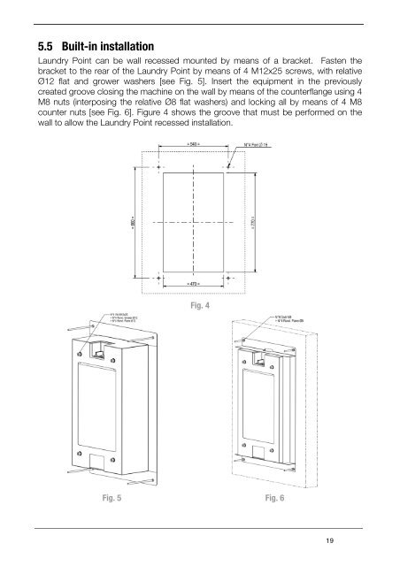
5.5 Built-in installationLaundry Point can be wall recessed mounted by means of a bracket. Fasten thebracket to the rear of the Laundry Point by means of 4 M12x25 screws, with relativeØ12 flat and grower washers [see Fig. 5]. Insert the equipment in the previouslycreated groove closing the machine on the wall by means of the counterflange using 4M8 nuts (interposing the relative Ø8 flat washers) and locking all by means of 4 M8counter nuts [see Fig. 6]. Figure 4 shows the groove that must be performed on thewall to allow the Laundry Point recessed installation.Fig. 4Fig. 5 Fig. 619
- Page 3 and 4: GUIDE TO THE SYMBOLS IN THIS MANUAL
- Page 5 and 6: Possible hazards from machine useIf
- Page 7 and 8: GENERAL GUARANTEE CONDITIONSPlease
- Page 9 and 10: B. Laundry Point configuration. ...
- Page 11 and 12: Upon receiving your product, make s
- Page 13 and 14: • A provider Card.• A User Card
- Page 15 and 16: 5.3 Name of the partsExternal viewA
- Page 17: Internal viewMA. SD Card.B. CPU.C.
- Page 21 and 22: A. Preliminary operations• Laundr
- Page 23 and 24: Link to Farnell websitehttp://it.fa
- Page 25 and 26: 24VDCCABLE RS485“-”“+”“A
- Page 27: The Dip-switch positions can be cha
- Page 30 and 31: Operating manual Laundry PointConne
- Page 32 and 33: Operating manual Laundry Point5-PIN
- Page 34 and 35: Operating manual Laundry Point34
- Page 36 and 37: Operating manual Laundry Point1 bio
- Page 38 and 39: Operating manual Laundry Point38
- Page 40 and 41: Operating manual Laundry PointWhen
- Page 42 and 43: Operating manual Laundry Point6.2 L
- Page 44 and 45: Operating manual Laundry Point7.2.
- Page 46 and 47: Operating manual Laundry Point1 Set
- Page 48 and 49: Operating manual Laundry PointOK00
- Page 50 and 51: Operating manual Laundry PointOK010
- Page 52 and 53: Operating manual Laundry PointOK =
- Page 54 and 55: Operating manual Laundry PointSetup
- Page 56 and 57: Operating manual Laundry PointOKESC
- Page 58 and 59: Operating manual Laundry Point20Dis
- Page 60 and 61: Operating manual Laundry PointOVRPA
- Page 62 and 63: Operating manual Laundry PointSetup
- Page 64 and 65: Operating manual Laundry PointWarni
- Page 66 and 67: Operating manual Laundry Point10. D
5.5 Built-in installation<strong>Laundry</strong> <strong>Point</strong> can be wall recessed mounted by means of a bracket. Fasten thebracket to the rear of the <strong>Laundry</strong> <strong>Point</strong> by means of 4 M12x25 screws, with relativeØ12 flat and grower washers [see Fig. 5]. Insert the equipment in the previouslycreated groove closing the machine on the wall by means of the counterflange using 4M8 nuts (interposing the relative Ø8 flat washers) and locking all by means of 4 M8counter nuts [see Fig. 6]. Figure 4 shows the groove that must be performed on thewall to allow the <strong>Laundry</strong> <strong>Point</strong> recessed installation.Fig. 4Fig. 5 Fig. 619


