Laundry Point - Comesterogroup
Laundry Point - Comesterogroup
Laundry Point - Comesterogroup

Create successful ePaper yourself
Turn your PDF publications into a flip-book with our unique Google optimized e-Paper software.
GUIDE TO THE SYMBOLS IN THIS MANUALThe following symbols have been included in this manual tofacilitate its consultation.Important informationRead carefully before useCaution!3
Operating manual <strong>Laundry</strong> <strong>Point</strong>DECLARATIONOF CONFORMITYTHE MANUFACTURER: <strong>Comesterogroup</strong> s.r.l. via M. Curie 8,20060 Gessate MIDECLARESThat the product:TYPE: laundrette activation systemBRAND: <strong>Comesterogroup</strong>MODEL: <strong>Laundry</strong> <strong>Point</strong>2004/108/ EECIs conform to the following European Directives, including their latest amendments, as well as to the nationalimplementation legislationAnd that the following harmonised standards have been applied:EN 61000-6-2EN 61000-6-3EN 60355-2-82Gessate, 15.05.09Riccardo Chionna , CEO <strong>Comesterogroup</strong> s.r.l.SAFETY INFORMATIONTo prevent damages caused by short circuits and fires, this machine is equipped withsafety devices.These devices must not, under any circumstance, be excludedfrom the circuit, nor must they be removedShould they be deactivated to carry out maintenance or repairoperations, it is possible to operate on the equipment only in absenceof electric power.The safety devices have been made in compliance with the regulationsin force.The operator must regularly verify the efficiency of the equipment.4
Possible hazards from machine useIf kept in good conditions and if installed correctly (according to the indications in thismanual), the machine does not expose the user to any kind of hazards.The personnel in charge of loading the dispensers, starting up the equipment and ofthe machine maintenance, must bear in mind that: all moving parts, doors and cashpoint,can cause various types of injuries if not handled correctly; moreover, it isimportant to disconnect the power supply for any operation carried out on the openequipment (maintenance, etc.)Risks from electricity: direct contacts during its connection to themain power supply.Operations to be carried out by qualified personnel.Crushing risk when handling the moving components of theequipment.The compartments must be opened and closed slowly and carefully.Risks during installation and preparation of the deviceFollow the installation instructions (paragraph 9), in order to minimise risks to peopleand objects.Crushing risk when positioning the equipment and handling itsmoving components.All equipment transport operations must be carried out by qualifiedpersonnel in load handling operations (forklift operators, etc.).Precautions:• Use adequate lifting devices and harnesses.• Carry out operations in areas that are free from obstacles and people.• Before lifting the load, verify its stability and perform all movements with caution.5
Operating manual <strong>Laundry</strong> <strong>Point</strong>Risks from electricity: direct contacts during its connection to themain power supply. Operations to be carried out by qualifiedpersonnel.Precautions:• Make sure that the distribution line is sized according to the intensity of thecurrent absorbed by the machine.• Carry out the earth connection before connecting equipment or aggregatedevices.Risks during the maintenance of the deviceRisks from electricity: direct contact with live parts inside theelectrical components cabinet.Operations to be carried out by qualified personnel.Precautions:• Operate on the machine only after ensuring that the main power switch isturned offSignsThe equipment is equipped with signs consisting of warning labels located near thehazardous areas that bear conventional danger symbols.DANGER RISK OF ELECTRIC SHOCK GROUNDING6
GENERAL GUARANTEE CONDITIONSPlease read the following carefully in order to understand the general warrantyconditions for fthis product.The supplied goods and services are guaranteed by our company for a period of 12months. The term of guarantee starts from the date of purchase (indicated on theinvoice). The guarantee is limited to the normal working order of the supplied goodsand to the result of the service provided. Products supplied are restored to normalworking order at our company site.Our company cannot be held liable for the working order of goods supplied operatingin environmental or technical conditions that are not conform to our specifications andwhich are described in the technical documentation. Moreover, our company cannotbe held liable for any direct or indirect damage not caused by the malfunctioning ofthe product.The guarantee is void should the purchaser default in the payment of the price.The guarantee will not be applied in the following cases:• tampering with the label displaying the serial number of the machine;• damage or breakage caused by transport;• damage or breakage caused by vandalism, natural disasters or maliciousactions;• incorrect installation or misinstallation of the product;• inadequate or malfunctioning electrical installations;• carelessness, negligence or incompetence in the use of the product;• non-compliance with the operating instructions;• interventions for alleged defects or convenience checks;• unauthorised interventions on the product.Any interference or tampering with the supplied goods by unauthorised persons willmake the guarantee void. We hereby declare that we have taken carefulconsideration, to the best of our knowledge and manufacturing practices, to theproblem of goods supplied being violated by parties who intentionally alter theirnormal working order. Nevertheless, we cannot be held liable for illegal conduct ordamage that may result from the fraudulent use of the supplied goods.7
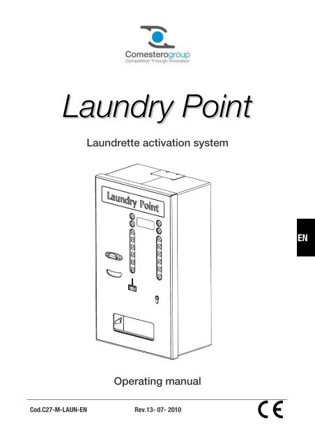
Operating manual <strong>Laundry</strong> <strong>Point</strong>Dear customer,Thank you for choosing a <strong>Comesterogroup</strong> product; by carefully following theindications of this instruction manual, you will be able to appreciate over time, andwith much satisfaction, the quality of our machines.Please read the use and maintenance instructions carefully and comply with all safetyprecautions before using the equipment. Keep this manual for future reference.ContentsContents.........................................................................................................................................81. Introduction.........................................................................................................................102. Product description ............................................................................................................103. Warnings .............................................................................................................................104. Handling and unpacking ....................................................................................................1184.1. Delivery of the packaged product..................................................................................... 114.2. Handling.......................................................................................................................... 114.3. Unpacking....................................................................................................................... 124.4. Equipment and accessory identification............................................................................ 125. Installation.............................................................................................................................135.1 Preliminary operations ........................................................................................................... 135.2 Overall dimensions ................................................................................................................ 145.3 Name of the parts............................................................................................................ 155.4 Wall installation ................................................................................................................ 185.5 Built-in installation............................................................................................................ 195. Connections ........................................................................................................................20A. Preliminary operations ........................................................................................................ 21B. Cabling ............................................................................................................................... 21C. Connection to the mains ..................................................................................................... 23D. Connection to the RS485 line .............................................................................................. 24E. Connecting the BIO boards.................................................................................................. 24F. Meaning of the LEDs on the BIO boards............................................................................... 27G. BIO board layout................................................................................................................. 29H Connection to the entire system ........................................................................................... 30H. Memory cards..................................................................................................................... 33I. Memory cards ...................................................................................................................... 396. Starting the equipment.......................................................................................................416.1 Loading the hopper with coins ......................................................................................... 416.2 Loading the dispenser with cards..................................................................................... 427. Operation and settings .......................................................................................................427.1. Basic operation................................................................................................................ 427.2. Advanced operation......................................................................................................... 44A. Card creation ...................................................................................................................... 44
B. <strong>Laundry</strong> <strong>Point</strong> configuration. ................................................................................................ 45C. Accounting ......................................................................................................................... 598. FW Update ...........................................................................................................................628.1. Saving configuration ........................................................................................................ 638.2. Preparing the SD Card..................................................................................................... 638.3. Updating the equipment................................................................................................... 638.4. Entering safety codes....................................................................................................... 648.5. Setting the equipment...................................................................................................... 649. Care and maintenance........................................................................................................649.1. Maintenance and external cleaning................................................................................... 659.2. Maintenance and internal cleaning.................................................................................... 659.3. Downtime........................................................................................................................ 6510. Diagnosis and technical assistance ..................................................................................6611. Technical data ....................................................................................................................6712. Annexes...............................................................................................................................6812.1. Decommissioning and disposal..................................................................................... 6812.2. Electric diagram ........................................................................................................... 719
Operating manual <strong>Laundry</strong> <strong>Point</strong>1. IntroductionThis manual and its annexes provide all the necessary information for a correctinstallation of the product and all its components, as well as for its correct use andmaintenance.The information contained in this manual can be modified without prior notice anddoes not constitute a commitment on behalf of <strong>Comesterogroup</strong>The information contained in this manual has been collected and verified with theutmost care; however, <strong>Comesterogroup</strong> has no liability arising from its use.Unless otherwise stated, any reference to companies (other than <strong>Comesterogroup</strong>),names, dates, and addresses is purely coincidental and has the sole purpose toillustrate the use of the product.The reproduction of any part of this manual without prior authorisation by<strong>Comesterogroup</strong> is prohibited.2. Product descriptionThe new <strong>Laundry</strong> <strong>Point</strong> has been designed to provide the self-service laundry marketwith a centralised cash-point of the highest quality at an extremely competitive price.<strong>Laundry</strong> <strong>Point</strong> can manage up to 12 different washing and drying machines and, foreach of its 12 programmes available, it accepts cash (coins or banknotes) or cardpayments.All operations are extremely simple and intuitive, thanks to the messages that appearon its wide display and to the 4 buttons that have different functions according to thesituation.<strong>Laundry</strong> <strong>Point</strong> offers a large number of advantages in terms user-friendly settings,firmware update and data export, thanks to the new removable SD card (very similarto common camera memories).Safety is ensured by a 3-point European cylinder lock.<strong>Laundry</strong> <strong>Point</strong> can be either built-in or wall-mounted.3. WarningsRead this manual carefully before installationThe indications and information contained in this manual are essentialfor a correct use of the product.10
Upon receiving your product, make sure it has not been damaged during transport.Pay attention to the electrical connections.Faults and malfunctions deriving from non-compliance with the instructions containedin this manual are not covered by guarantee.In this document, symbols are used to highlight important aspects that must becarefully observed.4. Handling and unpacking4.1. Delivery of the packaged productUpon receiving your product, make sure it has not been damaged during transport.Should you notice damage of whatever nature, contact the delivery company andimmediately file a complaint.Following transport, the package must be intact, i.e., it must not show:• Dents, signs of knocks, deformation or rupture of the packaging.• Wet or damp patches or signs which indicate that the package has beenexposed to rain, frost or heat.• Signs of tampering.After a first inspection, reinsert the machine in its packaging to bring it to its final pointof installation.4.2. HandlingTo prevent any damages to the machine, we recommend handling itinside its original packaging using adequate transport equipment.Follow carefully the handling instructions printed on the box.Considering the weight of the equipment, we recommend handling<strong>Laundry</strong> <strong>Point</strong> only by means of automatic or manual forklifts; shouldthis not be possible, slide the cash-point on its base or on an axisequipped with wheels to the point of installation.We recommend:not to drag the equipmentnot to tilt or place the packaging on its side during transport or when handling itnot to knock the equipmentnot to leave the machine exposed to weather agents (even if inside its packaging)11
Operating manual <strong>Laundry</strong> <strong>Point</strong>4.3. UnpackingThe equipment is delivered, following commissioning, in a corrugated cardboardpackaging, which ensures its integrity during transport and handling.To simplify loading/unloading of the product, even by means of adequate machines(transpallets), the box is laid on a wooden pallet.Follow the instructions printed on the box to unpack the equipment.Both the cardboard packaging and the pallet comply with thestandards regarding recycling and disposal (follow the regulations inforce in your country).4.4. Equipment and accessory identificationThe figures below show the location of the identification plate with all the mainoperating and identification features of the equipment. Very important is the serialnumber printed in the relative box.This number must always be stated in every request for assistance, spare parts,repairs or further information on the equipment.Fig. 1The machine identification plate must be clearly readable. Do not remove it. Do nottamper with the details shown on it. Should you damage or lose the identificationplate, request a replacement to the manufacturer. The plate is installed both on theoutside of the equipment and on the inside in the electrical connections compartment.Please remember that the guarantee is associated with the machine identificationnumber.The product is equipped with the following standard accessories included in thepackaging:• Operating manual• SD card (already installed).• An initialisation Card.12
• A provider Card.• A User Card.• Keys to the compartments:Three keys are provided to open the 3-point lock with which the equipment isprovided.We recommend having two sets of keys and keeping the spare ones in a safe placewhich must be different than the one normally used.5. Installation5.1 Preliminary operationsBefore installing <strong>Laundry</strong> <strong>Point</strong>, it is important to make sure all the machines havebeen correctly connected to the various services.In particular:• Make sure that the washing and drying machines are set to be connected to thepayment system (in case, verify with the machine supplier).• Make sure you have the wiring and connection diagrams of all the machines to beconnected available.• Connect all the machines to the relative systems (electrical, water, gas anddischarge) in compliance with the regulations in force.• Make sure there is a grounded socket near the <strong>Laundry</strong> <strong>Point</strong>; we also recommendproviding a lighting point near the cash-point.• Before installing the cash-point, arrange the connection cables in special conduitsas well as the BIO electronic boards that control the machines.The cash-point can be installed in three different manners according to thecustomer’s requirements.Recessed<strong>Laundry</strong> <strong>Point</strong> can be wall recessed mounted by means of a bracket.Wall-mounted<strong>Laundry</strong> <strong>Point</strong> has four pre-cut holes on the back of the cabinet for fastening it to thewall by means of plugs.13
Operating manual <strong>Laundry</strong> <strong>Point</strong>5.2 Overall dimensionsBelow is a series of images that show the overall dimensions of the equipment in itstwo installation options. Choose with care the place where to install the equipment toensure adequate stability.Suspended versionFig. 214
5.3 Name of the partsExternal viewA. Card/coin change compartment.B. Lock.C. Machine selection buttons.D. Function buttons.E. Display.F. Luminous plate (customisable).G. Door.H. Card readerI. Banknote reader.L. Coin acceptance.15
Operating manual <strong>Laundry</strong> <strong>Point</strong>A. Recessed fastening bracket/holes for fastening to the wall.B. Door.C. Power supply switch.D. RS485 (BIO interface) connector line.E. Wall hooking plate.F. Cabinet.16
Internal viewMA. SD Card.B. CPU.C. CPU connector area.D. Lock.E. Card supply conduit (optional).F. Coin mechanism.G. Banknote reader.H. Change return hopper.I. Card supply (optional).J. RS485 (BIO interface) connector line.K. Net filter.L. Card reader.M. RS485 line protection.17
Operating manual <strong>Laundry</strong> <strong>Point</strong>5.4 Wall installationThe figure below [Fig. 3] shows the heights [in mm] for fastening <strong>Laundry</strong> <strong>Point</strong> to thewall by means of plugs.<strong>Laundry</strong> <strong>Point</strong> has four pre-cut holes on the back of the cabinet for fastening it to thewall by means of plugs. Plugs must be chosen according to the wall and the weight ofthe equipment which is approximately 500 N [≈50 Kg].Fig. 3Alternatively, the equipment may be suspended by means of a bracket, which allowsgreater adjustment (see figure below).In this case, use the plugs to lock the wall bracket, levelling it through the eyeholes inthe bracket. At this point, insert the <strong>Laundry</strong> <strong>Point</strong> on the bracket locking the verticalmovement by means of 2 TE M8x16 screws with relative washers; then fasten thelower part of the equipment to the wall by means of 2 washers in order to preventtears to the frame.18
5.5 Built-in installation<strong>Laundry</strong> <strong>Point</strong> can be wall recessed mounted by means of a bracket. Fasten thebracket to the rear of the <strong>Laundry</strong> <strong>Point</strong> by means of 4 M12x25 screws, with relativeØ12 flat and grower washers [see Fig. 5]. Insert the equipment in the previouslycreated groove closing the machine on the wall by means of the counterflange using 4M8 nuts (interposing the relative Ø8 flat washers) and locking all by means of 4 M8counter nuts [see Fig. 6]. Figure 4 shows the groove that must be performed on thewall to allow the <strong>Laundry</strong> <strong>Point</strong> recessed installation.Fig. 4Fig. 5 Fig. 619
Operating manual <strong>Laundry</strong> <strong>Point</strong>5. ConnectionsBefore connecting the equipment to the electric mains, make surethat the main switch, located in the electric connection compartmentin the top rear part of the equipment, is set to “0”, off, as shown inthe figure below.Fig. 7Make sure that the distribution line is sized according to the intensityof the current absorbed by the machine.Carry out the earth connection before connecting equipment oraggregate devices.Note: As for installation, please refer to the specific standard regarding protectionagainst electrical contacts.All <strong>Laundry</strong> <strong>Point</strong> electric connections are installed on the machine except for:• Connection to the 230 Vac 50HZ electric mains.• Connection to RS485 peripheral devices (BIO boards optional).20
A. Preliminary operations• <strong>Laundry</strong> <strong>Point</strong> must be already placed on the wall or in its housing.• The power supply and signal cables must be already in place, starting from thecash-point and reaching all the machines without interruptions.• To simplify the connections, ensure a greater cable length near the cash-pointand all the machines (approximately 1 metre).• The presence of qualified personnel that know the washing and dryingmachines perfectly is required.It is important to have all the technical information regarding theduration of the washing/drying machine input enabling signal(amount of time required by the machines to receive the consentsignal from the cash-point).Make sure that the socket to which to connect the equipment is suited to the featuresof the equipment and that it is protected by an adequate differential magneto-thermalswitch.<strong>Laundry</strong> <strong>Point</strong> is supplied with a SNAP-IN connector and an IEC C13 socket.Note: Make sure the system is voltage free before connecting it to the mains.B. CablingThe RS485 cable must have:To be carried out before installing the automatic cash-point.To connect the machine to the BIO peripheral devices, the user mustpurchase two types of cables:1) A specific RS485 cable (A)2) A standard bi-polar power supply cable (B)a) A pair of twisted cables with a section of at least 0.26 mm².b) Shielding.As an example, references to BELDEN cables are shown in the data sheet below.21
Operating manual <strong>Laundry</strong> <strong>Point</strong>Fig. 8For urgent orders, please see the details for purchasing through one of the Farnellelectrical and electronic material distributors:Belden Code 9271 060500 — BELDEN — CABLE, 9271 TWINAX 153MCode Farnell 118216822
Link to Farnell websitehttp://it.farnell.com/jsp/Cable/Multicored/BELDEN/9271+060500/displayProduct.jsp?sku=1182168The power cable dedicated to the BIO boards is a standard bi-polar cable with a pair having a section of atleast 1mm².Use cables that include the GROUND cable to connect it to the laundry cash-pointgrounding.To prevent any “Antenna” effect, connect unused cables to the cash-point grounding.C. Connection to the mainsThe client is responsible for connecting the equipment to the electric mains andcreating a system in compliance with IEC 64-8 standard “Electric plant using nominalvoltages not higher than 100V in alternating current”Bring the neutral phase and ground power cable, to the rear of the cabinet andconnect it to the “IEC C13” connector provided with the machine in (see figure below).Fig. 9Connect the mains power supply (230 Volt 50Hz) to the SNAP-IN socket providedwith the machine.LNFig. 1023
Operating manual <strong>Laundry</strong> <strong>Point</strong>L = Phase 230 Volt 50Hz (Brown cable)N = Neutral 230 Volt 50Hz (Blue cable)= Ground (Yellow/Green cable)D. Connection to the RS485 lineTo pilot the washing/drying machines, <strong>Laundry</strong> <strong>Point</strong> uses BIO peripheral devices,which require connection to the RS485.On the upper part of the machine, on the green terminal board, there is a 5-pin panelconnector to pilot the BIO peripheral devices. The figure below shows theconnections of the two previously laid cables.MACHINE TRAY(PANEL CONNECTOR)24VDC“-”“+”“B”“A”CABLE RS485GROUNDFig. 11The special RS485 cable is equipped with a screen. This screen must be connectedto the <strong>Laundry</strong> <strong>Point</strong> grounding (central connector terminal).E. Connecting the BIO boardsThe BIO electronic boards pilot the washing and drying machines in the premises.Each BIO board is associated to an appliance and bust be connected the same way,as in the figure below.24
24VDCCABLE RS485“-”“+”“A”“B”1CN1RELE’RELE’CN21CN31CN41NONCCOMNONCCOMGND+12VdcMACHINEENABLINGQUICKMACHINEENABLINGCN51“-”“+”“-”“+”MACHINEPOWEREDMACHINEBUSYMACHINE ADDRESS(DIP-SWITCH)1 2 3 4 5 6ONCN61NOT USEDCOMESTEROConnector CN1Fig. 12This is the BIO board power connector.Both the inverting and non-inverting RS485 signals must reach Pin3 and Pin4. Thesesignals come from the automatic cash-point. The specific RS485 cable (A) must beused.The 24Volt board power supply must be connected on Pin1 and Pin2 This cablecomes from the automatic cash-point. The standard bipolar (B) must be used.Connector CN2This is the (washing/drying) machine activation connector.The “Common” signal reaches Pin1, while on Pin2 there is the NC relay contact andon Pin3 the NO contact.Connector CN3This connector replicates the same activation signals as connector CN2Its activation times are a 10 thof CN2. (for washing machines that require quickactivation time).Connector CN4The board can read signals coming from the washing and drying machines, such as“Machine Busy” and “Machine powered”. These inputs are used to signal when themachine is already in operation and when the machine is powered. The input interfacewith the BIO board is opto-isolated.A 12 Vdc power supply is present on this connector, should themachine signals be voltage-free contacts, such as relays. Thispower supply can be brought to the machine voltage-free contactheads and the signal can be brought to the BIO board inputs.25
Operating manual <strong>Laundry</strong> <strong>Point</strong>Connector CN5This is the board input connector. Terminal 1 and terminal 2 are the positive andnegative inputs of the “Machine powered” signal. This signal is activated when themachines are powered. Terminal 3 and terminal 4 are the positive and negative inputsof the “Machine Busy” signal. This signal is activated when the machine is inoperation.Connector CN6Normally NOT USED.In case of direct voltage, the signals must be connected accordingto the polarity indicated in the diagram. In case of alternate voltage,polarity is not important. The allowed voltage ranges are thefollowing: 5 ÷ 30 V in DC - 5 ÷ 230 V in AC.All machines piloted by <strong>Laundry</strong> <strong>Point</strong> must have a “Machine Number”. The machinenumber is the address set on the BIO board. To assign an address, the Dip-Switcheson the board are moved.The BIO board addresses are composed using a binary code on dip-switch SW1,installed on the printed circuit.Below are the switch combinations that represent the first thirty addresses. The Dipswitchpositions can be changed even when the BIO board is powered. The board willbe immediately operative with the new address setting.Address Dip-Switch Address Dip-Switch Address Dip-Switch12345678910ON1 2 3 4 5 6ON1 2 3 4 5 6ON1 2 3 4 5 6ON1 2 3 4 5 6ON1 2 3 4 5 6ON1 2 3 4 5 6ON1 2 3 4 5 6ON1 2 3 4 5 6ON1 2 3 4 5 6ON1 2 3 4 5 611121314151617181920ON1 2 3 4 5 6ON1 2 3 4 5 6ON1 2 3 4 5 6ON1 2 3 4 5 6ON1 2 3 4 5 6ON1 2 3 4 5 6ON1 2 3 4 5 6ON1 2 3 4 5 6ON1 2 3 4 5 6ON1 2 3 4 5 621222324252627282930ON1 2 3 4 5 6ON1 2 3 4 5 6ON1 2 3 4 5 6ON1 2 3 4 5 6ON1 2 3 4 5 6ON1 2 3 4 5 6ON1 2 3 4 5 6ON1 2 3 4 5 6ON1 2 3 4 5 6ON1 2 3 4 5 626
The Dip-switch positions can be changed even when the BIO board is powered. Theboard will be immediately operative with the new address setting.F. Meaning of the LEDs on the BIO boardsThe LEDs on the BIO board are useful to understand the board status.1CN 6SW 12D18341CN 5D2023D2241CN 4D2421CN 3D20 D10231CN 2D164323D1421Fig. 13The image shows the position of the main LEDs. The first one is not represented andis on only when the BIO board is on.Led D14Represents the status of the "Start Enable" output. When the output is activated, theLED is on. When the output is deactivated, the LED is off.Led D16Currently not used.27
G. BIO board layoutInformation on Bio board connections is provided below.Fig. 14Connector CN2"Start enable" signal relay contacts (Machine enabling output).Connector CN3Not usedConnector CN4When the (washing/drying) machine signals are voltage-free outputs (relays), thevoltage generated by this connector can be used to power the contacts.29
Operating manual <strong>Laundry</strong> <strong>Point</strong>Connector CN5 – “machine powered” inputIt must be connected to check whether the <strong>Laundry</strong> <strong>Point</strong> board is powered.Connector CN5 – “machine busy” inputIt must be connected to verify the "Busy" signal (the machine is operating).Connector CN6Not usedLed D20This red LED must flash very quickly almost seeming as if it were always on. If it’s notflashing this way, there are firmware problems on the BIO board. Should this be thecase, please contact technical service to replace the BIO boards.Led D10This yellow LED flashes when the <strong>Laundry</strong> <strong>Point</strong> system is verifying the entirenetwork.Should the LED not be flashing, there may be some connection problems betweenthe BIO board and the <strong>Laundry</strong> <strong>Point</strong> system. Should this be the case, verify all thecables.SW1Used to set the address on the BIO board on the network. For its configuration,please refer to the section BIOBIO_board_address_composition.Voltage technical specifications to stimulate the inputs:• from 5 Vdc to 30 Vdc• from 5 Vdc to 230 VdcH. Connection to the entire systemThere are two ways to connect <strong>Laundry</strong> <strong>Point</strong> automatic cash-point to the machinesin the premises:1. The cash-point on the wall and the washing and drying machines all in line. Thismeans that the RS485 connections are carried out as a single chain (figure 16).2. The cash-point at the centre of the premises and the washing and dryingmachines arranged in one or more branches (figure 17).In both cases, starting from the cash-point tray connector, one or more chains of the24 Volt and RS485 cables are carried out.30
Caution: always comply with the polarity as described in this document.In the RS485 cable chain to be laid in the shielding (screen) in thevarious cables must be connected between them with a singleGROUND point for the cash-point.5-PIN CONNECTORRS485RS485 CABLE24 VOLT POWER CABLEFig. 1531
Operating manual <strong>Laundry</strong> <strong>Point</strong>5-PIN CONNECTORRS48524 VOLT POWER CABLERS485 CABLEFig. 1632
I. Connecting 3BIO BoardTo control the 3BIO board, a 5-pole panel connector is installed on the machine. It isthe green terminal. The figure below shows the connections of the two previously laidcables.MACHINE TRAY(PANEL CONNECTOR)24VDC“-”“+”BRAID“B”“A”RS485 CABLEFig. 4The special RS485 cable is equipped with a shielding braid. This shielding braid mustbe connected to the machine's grounding by means of the central terminal of theterminal board (braid).33
Operating manual <strong>Laundry</strong> <strong>Point</strong>34
Up to three machines can be connected to the 3BIO board (e.g.: washing and dryingmachines).Connect the end of cycle/machine busy signal outputs (IN) of machine 1 to connectorCN2, of machine 2 to connector CN4, of machine 3 to connector CN7.Connect the output/activation signals (OUT) to the equipment as indicated in theconnection diagram:Machine1 connector CN1Machine2 connector CN3Machine3 connector CN5Caution! Connect the equipment to the 3BIO board respecting thepolarity indicated in the connection diagram.Do not invert polarity!Each 3 Bio card can handle up to 3 machines. <strong>Laundry</strong> point recognises machines inblocks of 3.A rotating switch is present on each card for assigning addresses. Connect the firstthree machines to the first 3 Bio card, assigning the number 1 as address on therotating switch. To connect additional machines, add a second 3 Bio card.Connecting the washing/drying machines to the normal terminals on the second card,assign to the latter the address number 4 via the rotating switch. In the case of a thirdcard the address is 7, of a fourth 10 and so on.Below are examples of connection of only 3 Bio cards or mixed use of Bio and 3 Biocards. The number in bold in the table indicates the number of the address to be seton the card switch.• In the case of connection of only 3 Bio cards1234567893 bio3 bio3 bio• In the case of mixed connection of Bio and 3 Bio cards35
Operating manual <strong>Laundry</strong> <strong>Point</strong>1 bio23 bio3453 bio678 bio9N.B. The sequence of address assignment to machines must be consecutive, that is withoutinterruptions or inversions. Otherwise malfunction may occur. A correct example of addressassignment is given below.36
Example of correct address assignment of 3 Bio cards:13 Bio Card1 2 3set address 11 2 3machines23 Bio Card4 5 64 5 6set address 4machines3 Bio 3 Card7 8 9set address 77machinesN.B. If only 2 machines are connected to the 3 Bio card, always set the address as number1. On the second card, for subsequent machines, the address must be 4, otherwise machinemalfunctions may occur.Connect a 24VDC ±5% power supply line to power supply terminal CN7 (PWR).Caution! Respect the indicated values and the polarity for connectingthe power supply line.The 3BIO board is equipped with LED indicator lights to indicate the status.As indicated in the previous connection diagram, LED D1, when red, indicates theincorrect reception of data from the machine (cash-point).LED D2, when green and steady, indicates the correct connection with the machine(cash-point).37
Operating manual <strong>Laundry</strong> <strong>Point</strong>38
L. Memory cardsThe automatic cash-point is equipped with a multi-purpose Chip Cards, which can beidentified by the privilege associated to them.The available privileges are the following:• Cash-point initialisation.• Provider.• Prepaid.The functions of each privilege are explained in detail below.L.1 Safety and recognition systemsBefore providing further details on the card functions, it is important to point out howthey are managed in order to guarantee a high level of safety to protect the interestsof the owners of the single cards.SafetyThe content of the card is encrypted to prevent any fraud attempts.RecognitionTo prevent a card from being used on a <strong>Laundry</strong> <strong>Point</strong> for which it was not intendedfor, a 128 bit recognition code is set on every <strong>Laundry</strong> <strong>Point</strong> and is compared with thecard code.A recognition code is univocally assigned by <strong>Comesterogroup</strong> to every cash-point.Should the cash-point and card codes not coincide, the card is signalled as incorrect.Recognition codes are valid for every type of card.There are no passe-partout mechanisms.If, for instance, a technician must carry out maintenance operations on10 cash-points, he must have 10 different cards to assess the cashpoints.L.2 PrivilegesInitialisation cardWhen they are manufactured, the cash-points do not have the card recognitioncodes.When a cash-point is not initialised, a message will appear on the screen and anyselection will fail.Every cash-point is equipped with an initialisation card with the codes to assign to thecash-point.39
Operating manual <strong>Laundry</strong> <strong>Point</strong>When the initialisation card is inserted in the (non-initialised) cash-point, the codescontained in the card are copied in the cash-point.The cash-point is automatically restarted and from that point onwards, it will operatewith the assigned codes.Once a cash-point is initialised, the codes can no longer be changed.Should you require two or more cash-points to operate with the samecard, they must be initialised with the same initialisation card.This procedure is always necessary after every machine update. (SeeSD Card paragraph).Provider cardOnce this card is inserted in the (previously initialised) cash-point, you can access theconfiguration and accounting programme.The purpose of this card is to allow access to economic information stored in thecash-point. In particular, the owner/s of this card can:• modify the machine and product prices.• view accounting.• delete accounting/events• create new provider, technical or sub-provider cards.The provider card does not allow adding or removing machines fromthe configuration.Also, it does not allow changing the BIO board inputs and outputsmanagement.A copy of this type of card is provided with the cash-point.Prepaid cardThis is the card intended to be inserted in the card dispenser to be sold to the endcustomer.This means that the customer can purchase this type of card (using cash only) anduse the credit contained in it to pay for services and products.The customer can recharge the card with cash either insertingmoney first and then the card or vice-versa.In case of failure to dispense a product paid with the card, the sumof the product is returned in cash.Before inserting the card in the dispenser, proceed as follows:40
3. Set the card pre-charged credit value (“Credit in new card” parameter in theconfiguration and commissioning tool “Various” page).4. Enter the configuration and commissioning tool “Card” page and initialise thecard number to be placed in the dispenser5. Insert the initialised cards in the card dispenser6. Restart the cash-point.6. Starting the equipmentCarefully read the following instructions before starting up your <strong>Laundry</strong> <strong>Point</strong>.6.1 Loading the hopper with coinsIn order to return the change in coins, the hopper must be loaded approximately ¼ ofits capacity.Note: We recommend not loading the hopper too much or it would drastically reducepayment with coins.Fig. 1741
Operating manual <strong>Laundry</strong> <strong>Point</strong>6.2 Loading the dispenser with cardsLift the counterweight bracket inside the card dispensing container and load thedispenser with cards as shown in the figure, making sure they are placed horizontallyto the dispenser base and are not tilted.Fig. 187. Operation and settings7.1. Basic operationEvery <strong>Laundry</strong> <strong>Point</strong> is commissioned and initialised within <strong>Comesterogroup</strong>. Themachine protection codes are inserted during the commissioning stage.Inside the <strong>Laundry</strong> <strong>Point</strong>, you will find an initialisation card, which consists in reinsertingthe machine safety codes when necessary, like, for example, after everyupdate.<strong>Laundry</strong> <strong>Point</strong> is equipped with a graphic display (B), which guides the user throughthe basic operation and configuration procedures.At the corners of the display, there are 4 luminous buttons (C), which allow selectingthe corresponding functions.On the first “User Menu” screen, you can choose the language by pressing one of thebuttons on the side of the display.By pressing one of the machine buttons, the price for the required service will bedisplayed.42
ITALInsert cardor cashFRANENGL08 : 30 : 26ESPABy inserting a card or cash, the available credit will be displayed and you will berequired to select a machine or to purchase a card (this option is valid only whenpaying cash).Credit available10 €Select a machineor press CARD08 : 30 : 26CARDIf you select a machine, the service associated with that machine (e.g.: washing) willbe provided and the change returned.Change6.50 €Dispensing08 : 30 : 26• When insufficient credit is inserted, the message:• “INSUFFICIENT CREDIT” will appear.• Should the selected machine not be available, the message: “MACHINE BUSY”will appear.• Should the change not be returned, the message: “SIGNAL THE FOLLOWINGNUMBER TO REQUEST YOUR UNRETURNED CHANGE” will appear, followedby a digit code.43
Operating manual <strong>Laundry</strong> <strong>Point</strong>7.2. Advanced operationInsert the Provider card to access the machine configuration parameters.There are three main functions available in the menu:a) Card creation.b) <strong>Laundry</strong> <strong>Point</strong> configuration.c) Accounting.CONFCARDProviderSelectanoperationACC.ESCA. Card creationSelect “CARD” to access the card creation menu.CONFCARDProviderSelectanoperationACC.ESC• Select “GEST” to create a provider card.• Select “PREP” to create a prepaid card.44
PROV.PREPSelectthe typeof cardto be createdESCThe display will show the message: “INSERT BLANK CARD”.Introduce a blank card and wait a few seconds. Once the creation process iscompleted, the display will show the message: “NEW CARD CORRECTLY SET”.B. <strong>Laundry</strong> <strong>Point</strong> configuration.Select “CONF” from the first screen of the provider menu. This will allow you to accessthe <strong>Laundry</strong> <strong>Point</strong> configuration menu.CONFCARDProviderSelectanoperationACC.ESCFrom the “provider” screen, choose between:Setup 1.Setup 2.Setup 3.Setup 4.Setup 5.Every setup has some functionsThe “>>” button is used to proceed to the next screen.45
Operating manual <strong>Laundry</strong> <strong>Point</strong>1 Setup 1MACCSetup 1SelectanoperationSAVE>> ESCMACCBy selecting “MACC” you can set all the (washing/drying) machines in the premises aswell as the type of activation.Select one of the machines to be set with one of the activation buttons, from one totwelve.Once the button has been pressed, the following screen will be displayed and thebutton will start flashing until setting is completed.The buttons for the available selections are on the side of the display.The first menu available is the (washing/drying) machine activation. When not enabled,once the button is pressed, it will be shown as not availableOFFEnablingMachineenabledONOKESCOFF = Disables the (washing/drying) machine.ON = Enables the (washing/drying) machine.OK = Confirms the inserted data and displays the next screen: “Price withCard”.This menu is for setting the price for users that possess a card.46
ESC> = Moves the cursor to the right of the price.Buttons from one to nine modify the number highlighted by the cursor (1=1, 2=2…);button ten (10) changes the number to zero (10=0), while buttons eleven and twelveare not used (11 e 12).OK = Confirms the inserted data and displays the next screen: “Price withCash”.This menu is for setting the price for users that pay cash.ESC> = Moves the cursor to the right of the price.Buttons from one to nine modify the number highlighted by the cursor (1=1, 2=2…);button ten (10) changes the number to zero (10=0), while buttons eleven and twelveare not used (11 e 12).OK = Confirms the inserted data and displays the next screen: “Machineactivation time”.It is the amount of time during which the BIO board output relay remains active toenable the (washing/drying) machine.47
Operating manual <strong>Laundry</strong> <strong>Point</strong>OK00 : 30 : 0ESC> = Moves the cursor to the right of the time.Buttons from one to nine modify the number highlighted by the cursor (1=1, 2=2…);button ten (10) changes the number to zero (10=0), while buttons eleven and twelveare not used (11 e 12).OK = Confirms the inserted data and displays the next screen: “Input Polarity”.It is the level of the "machine busy" signal, when present on the washing/dryingmachine.OFFInput polarityMachine BusyHighONOKESCOFF = LOW level machine busyON = HIGH level machine busyOK = Confirms the inserted data and displays the next screen: “View remainingtime”.For some machines, it may be useful to view the remaining time of the washing/dryingcycle, should there not be a display on the machine.48
OFFViewRemaining timeEnabledONOKESCOFF = Deactivates the display of remaining time.ON = Activates the display of remaining time.OK = Confirms and returns to the initial screen.SAVEBy selecting SAVE, all the entered configuration data are stored.Setup 2.MACCSetup 1SelectanoperationSAVE>> ESCCARDSetup 2SelectanoperationCLCK>> ESCCARDBy selecting CARD, you can set the presence of the Card Dispenser and the cardvalue.49
Operating manual <strong>Laundry</strong> <strong>Point</strong>OK0100.000002.000000.10ESC> = Moves the cursor to the right of the price.Buttons from one to nine modify the number highlighted by the cursor (1=1, 2=2…);button ten (10) changes the number to zero (10=0), while buttons eleven and twelveare not used (11 e 12).OK = Confirms the inserted data and displays the next screen: “Card Value”.OK0100.000005.000000.10ESCThe Card Value is the amount of money with which the card is charged when creatinga prepaid card. The value can also be set to zero.> = Moves the cursor to the right of the price.Buttons from one to nine modify the number highlighted by the cursor (1=1, 2=2…);button ten (10) changes the number to zero (10=0), while buttons eleven and twelve(11 e 12) are not used.OK = Confirms the inserted data and displays the next screen: “Enable CardDispenser”.50
OFFEnableCard dispenserENABLEDONOKESCOFF = Disables the presence of the card dispenser.>> = Enables the presence of the card dispenser.OK = Confirms and returns to the initial screen.CLCKCARDSetup 2SelectanoperationCLCK>> ESCBy selecting CLCK you can set the <strong>Laundry</strong> <strong>Point</strong> clock.OK0ESC> = Moves the cursor to the right of the time.The twelve activation points are used to modify the number where the cursor ispositioned.Buttons from one to nine modify the number highlighted by the cursor (1=1, 2=2…);button ten (10) changes the number to zero (10=0), while buttons eleven and twelveare not used (11 e 12).51
Operating manual <strong>Laundry</strong> <strong>Point</strong>OK = Confirms the inserted data and displays the next screen: “Minutes”.ESC> = Moves the cursor to the right of the minutes.Buttons from one to nine modify the number highlighted by the cursor (1=1, 2=2…);button ten (10) changes the number to zero (10=0), while buttons eleven and twelveare not used (11 e 12).OK = Confirms the inserted data and displays the next screen: “Date”.ESC> = Moves the cursor to the right of the day.The twelve activation points are used to modify the number where the cursor ispositioned.Buttons from one to nine modify the number highlighted by the cursor (1=1, 2=2…);button ten (10) changes the number to zero (10=0), while buttons eleven and twelveare not used (11 e 12).OK = Confirms the inserted data and displays the next screen: “Month”.52
ESC> = Moves the cursor to the right of the month.The twelve activation points are used to modify the number where the cursor ispositioned.Buttons from one to nine modify the number highlighted by the cursor (1=1, 2=2…);button ten (10) changes the number to zero (10=0), while buttons eleven and twelveare not used (11 e 12).OK = Confirms the inserted data and displays the next screen: “Year”.OK2000ESC> = Moves the cursor to the right of the year.The twelve activation points are used to modify the number where the cursor ispositioned.Buttons from one to nine modify the number highlighted by the cursor (1=1, 2=2…);button ten (10) changes the number to zero (10=0), while buttons eleven and twelveare not used (11 e 12).OK = Confirms and returns to the initial screen.53
Operating manual <strong>Laundry</strong> <strong>Point</strong>Setup 3.CASHSetup 3SelectanoperationVARIOUS>> ESCCASHBy selecting CASH, you can set all the enabled coins and banknotes.OFFAcceptance10 centsEnableONOKESCOFF = Disables acceptance of the displayed coin/banknote.ON = Enables acceptance of the displayed coin/banknote.OK = Confirms the inserted data and displays the next screen.Coin and banknote recognition screens follow until the 50 € screen for the banknotereader.The machine accepts coins from 0.10€ to 2€ and banknotes up to 50€.CASHSetup 3SelectanoperationVARIOUS>> ESC54
VARIOUSBy selecting VARIOUS you can set the all the other <strong>Laundry</strong> <strong>Point</strong> functions.OK1ESC> = Moves the cursor to the right of the overpay time.Buttons from one to nine modify the number highlighted by the cursor (1=1, 2=2…);button ten (10) changes the number to zero (10=0), while buttons eleven and twelveare not used (11 e 12).OK = Confirms the inserted data and displays the next screen: “Max. Change”.ESC> = Moves the cursor to the right of the maximum change.The twelve activation points are used to modify the number where the cursor ispositioned.Buttons from one to nine modify the number highlighted by the cursor (1=1, 2=2…);button ten (10) changes the number to zero (10=0), while buttons eleven and twelve(11 e 12) are not used.OK = Confirms the inserted data and displays the next screen: “Language”.This is the “basic” <strong>Laundry</strong> <strong>Point</strong> language.55
Operating manual <strong>Laundry</strong> <strong>Point</strong>OKESC> = With these buttons you can shift to the required language.OK = Confirms the inserted data and displays the initial screen.Setup 4.To enter test mode, you must access Setup 4 in the Configuration menu.TESTSetup 4Selectanoperation>> ESC(WASHING/DRYING) machine test – MACHBy selecting “MACH”, you access the menu where to control all <strong>Laundry</strong> <strong>Point</strong>commands to the (washing/drying) machines.MACHVARIOUSTest menuChoose aTestAreaCASHESC56
Machine start-upChoosemachineRemaining time>> 0:00 ESCWith activation buttons from 1 to 12, the machines connected to <strong>Laundry</strong> <strong>Point</strong> arestarted without inserting cash.During this stage you can verify whether the connection to the machines has beencarried out correctly.The “>>” button is used to proceed to the next function “Input test”.Input testBy activatingThe inputsThe buttons>> Light up ESCBy stimulating the BIO boards, the <strong>Laundry</strong> <strong>Point</strong> buttons referring to that machine willlight up. For example, washing machine 1 active (machine busy), button (1) on the<strong>Laundry</strong> <strong>Point</strong> will light up.Payment system test - CASHBy selecting CASH, you access the menu for controlling the coin/banknoteacceptance and coin dispensing systems.MACHVARIOUSTest menuChoose aTestAreaCASHESC57
Operating manual <strong>Laundry</strong> <strong>Point</strong>20Discriminator test10Choosesum>> ESCSelect the required sum using the buttons on the side of the display and verify that<strong>Laundry</strong> <strong>Point</strong> is managing it correctly.The “>>” button is used to proceed to the next function “Coin mechanism test”.Coin mechanismtestInsertcoins0.50>> ESCInsert the coins and verify that they are accepted and indicated correctlyThe “>>” button is used to proceed to the next function “Banknote reader test”.Banknotereader testInsertBanknote20.00>> ESCInsert the banknotes and verify that they are accepted and indicated correctly.Card dispenser test - VARIOUSBy selecting VARIOUS, you access the card testing menu.58
MACHVARIOUSTest menuChoose aTestAreaCASHESCCard dispensertestDISP.>> ESCPress“DISP” to verify that the Card is dispensed correctly.C. AccountingCONFCARDProviderSelect anoperationACC.ESCThe ACC. menu contains all the information regarding <strong>Laundry</strong> <strong>Point</strong> inputs andoutputs.59
Operating manual <strong>Laundry</strong> <strong>Point</strong>OVRPAccounting orOverpaySelect anoperationACC.ESCThe accounting menu displays the machine meters, which can be reset (RESET).Total accountingRESETInserted: 178.00Dispensed: 58.00Charged card: 74.00Sold cash: 6.00Sold card: 43.00Sold cards: 4>> ESCBy pressing “>>” the partial meters are reset.Partial accountingRESETInserted: 88.00Dispensed: 18.00Charged card: 10.00Sold cash: 10.00Sold card: 5.00Sold cards: 2>> ESCOverpayOverpay events occur when coins/cards fail to be sold or dispensed. This menucontains a list of all these events with the associated date, time and number.• Select “CANC” to delete the overpay events list (and YES or NO to delete thelist in that screen or not)• Select LIST to display the overpay events list (and >> or
• “ESC” to exit.CANCOverpaySelectAnoperationLISTESCIn these situations, the machine displays the number associated with the anomaly tothe end customer.OKESCThe bar on the upper part of the display represents the number of events in the listand the position of the event being viewed.The last element of the list is the latest event occurred.The list can be deleted by pressing CANC.Should no overpay event occur, the display will show the message:“ INFORMATION NO OVERPAY PRESS A BUTTON”.Import / Export – Setup 5<strong>Laundry</strong> <strong>Point</strong> allows exporting and importing data through the SD Card.EXPSetup 5SelectAnoperationIMPESC61
Operating manual <strong>Laundry</strong> <strong>Point</strong>Setup 5 includes the following functions.ExportCONFLANGExportSelectWhatTo exportCONTESCCONF =ACC. =LANG =Exports <strong>Laundry</strong> <strong>Point</strong> configuration.Exports <strong>Laundry</strong> <strong>Point</strong> accounting.Exports the <strong>Laundry</strong> <strong>Point</strong> set of languages.ImportCONFImportSelectWhatTo importLANGESCCONF =ACC. =Imports the configuration from SD Card to the <strong>Laundry</strong> <strong>Point</strong>.Imports the set of languages from the SD Card.8. FW Update<strong>Laundry</strong> <strong>Point</strong> can be easily updated by means of the SD Card alone.The machine is designed in such a way as to prevent any problem when updating.Even during a sudden power outage, the machine can complete the procedure whenrestarted.62
Warning After every <strong>Laundry</strong> <strong>Point</strong> update, the configuration data andthe safety codes are lost. Once the update is completed, themachine must be initialised and configured.8.1. Saving configurationThe first operation to be performed is to save all <strong>Laundry</strong> <strong>Point</strong> configuration data.To carry out this operation, you will need the SD Card provided inside the machine.a) Insert the Card in its slot.b) Power the machine.c) Insert the Provider Card.d) Select CONF (configuration).e) Select “>>” until reaching setup 5.f) Select EXP and then CONF.This way, you have just saved your configuration in the memory.8.2. Preparing the SD Card.Warning Contact <strong>Comesterogroup</strong> Customer Service for the latestversion of <strong>Laundry</strong> <strong>Point</strong> available.a) Insert the SD Card in a memory card reader.b) Copy the file you have received by e-mail in the SD Card main folder(HostApplication.bin).8.3. Updating the equipmentPerform these simple operations to prepare the equipment:a) Disconnect the power from the system.b) Insert the prepared SD card in its slot.c) To start the machine update, all you have to do is power the <strong>Laundry</strong> <strong>Point</strong> andwait for the display to show the message: “upgrading…”d) Once the update is completed, the machine carries out a full restart and themessages of normal operation will be displayed.e) Remove the SD card from the machine.f) Delete the Card file should you want to use the same one for storingaccounting.63
Operating manual <strong>Laundry</strong> <strong>Point</strong>Warning the file must be deleted from the SD Card after an update; afterevery start-up, <strong>Laundry</strong> <strong>Point</strong> will be updated and will lose itsconfiguration and safety codes.8.4. Entering safety codesAfter every update, the machine stops with the following screen.Assigncodes tothe cash-pointInsertinitialisation cardInsert the initialisation card provided.Should it be damaged or lost, please contact <strong>Comesterogroup</strong>. Please remember totake note of the machine serial number, since you will be asked.8.5. Setting the equipmentOnce all the safety codes have been inserted by means of the initialisation card, thereare two ways to carry out the settings:1) If you have saved the configuration in the SD Card, all you have to do isimport said configuration.2) If you have forgotten to save the configuration, you will have to proceed bysteps, setting all the functions.9. Care and maintenanceAll maintenance operations carried out inside the machine must becarried out with the power supply disconnected.64
We strongly recommend following these instructions carefully in orderto always keep the validator in the best operating conditions and toprevent dangerous situations that would make the guarantee void.9.1. Maintenance and external cleaningAlways keep the external surfaces of the equipment clean; to do so, we recommendusing a damp cloth or a mild detergent.Do not use aggressive chemical solvents that could damage the equipment finishes.Do not submerge in or expose the equipment to water or other liquids of whatevernature.Regularly verify the equipment surfaces with special attention to those areas that, dueto normal operation conditions, could represent a hazard for the user (sharp plates,rusty areas, etc.).9.2. Maintenance and internal cleaningClean the inside of the machine with a cloth damped with water; for theelectrical/electronic components use only compressed air.Regularly check the cable connections making sure the peripheral device connectioncables do not have points that are not insulated and are not excessively twisted.Replace cables and connectors immediately should they present any anomaly.9.3. DowntimeIn periods when the machine will not be used for two or three days, we recommendturning the equipment off by means of the master switch.For longer downtime periods, we recommend disconnecting the equipment from themains by disconnecting the plug from the socket.Protect the equipment from dust by covering it with a tarp and storing it in a dry andventilated place.65
Operating manual <strong>Laundry</strong> <strong>Point</strong>10. Diagnosis and technical assistanceIn this section are described the main anomalies that may occur using this product,with the possible solutions to minimise or eliminate machine downtime.If the problem you are encountering is not described here or shouldthe solution not solve it, please contact our after-sales service at:02/95781111CauseSolutionMake sure the cable is connected to thepower supply.The equipment does not turn onThe equipment does not accept theinserted coins.The equipment does not acceptbanknotes.The banknote accepts cash but doesnot credit it.Poor banknote acceptance by thereader.Make sure the master switch is in “I”position.Make sure the 2 protection fuses are notburnt.Make sure the change return hopper is nottoo full.Make sure there are no banknotes stuck atthe bottom of the readerMake sure the banknote drawer is not full.Make sure the inserted banknote value isconfigured in the banknote value table.Disconnect the reader and open it. Cleanboth the upper and lower part of the LEDsensors with a damp cloth.Make sure the reader is perfectly closed.66
11. Technical dataDimensions(lxhxd) (mm) 456 x 764 x 267Weight (Kg) Approx. 50Power supply230 VacPower consumption:120 VAWorking temperature:Installed peripheral devices:- Electronic coin mechanism- Banknote reader equipped with stacker- Card reader- Multi-coin dispenserCoins accepted: Programmable among 10c - 20c - 50c -1€ - 2€Dispensed coins:All accepted coin values, up to amaximum of 5.Banknotes accepted: Programmable 5€ - 10€ - 20€ - 50€Capacity:600 coins – 300 banknotes67
Operating manual <strong>Laundry</strong> <strong>Point</strong>12. Annexes12.1. Decommissioning and disposalAt the end of its intended life, the product must be decommissioned and disposed ofat a recycling site.Remove the equipment from its installation site, empty all the coins out of it andremove the power supply cable. Contact <strong>Comesterogroup</strong> to pick up the obsoleteequipment. Call: +39 02/9578111.This equipment must be disposed of in compliance with Legislative Decree No. 151dated 25/07/2005.Please read carefully the following information.As of the 31st December 2006, specific guidelines regarding the disposal of electricaland electronic equipment (WEEE) have been established to protect the environment.This equipment falls into the scope of Legislative Decree 151/2005 Annex 1B art. 2paragraph 1 being:7.6 A coin / token machine10.2 An automatic cash or vending machineIn summary:• This equipment is not to be disposed of as unsorted municipal waste but mustbe disposed of separately.• Dealers will pick up used equipment free of charge and take it to appropriaterecycling centres for its correct disassembly and possible recovery of the usedmaterials.• Special centres have been specifically created for the disposal of electrical andelectronic equipment (WEEE). The user can return this used equipment tohis/her local dealer when purchasing a new equivalent machine.68
• This equipment or parts of it may cause potentially hazardous effects on theenvironment and on human health if used improperly or if not disposed of incompliance with the procedure described above, due to the presence of somesubstances in the electronic components.• The crossed-out wheeled bin symbol printed visibly on this equipment indicatesthat this product has been placed on the market after 13 August 2005 andmust be disposed of separately.Sanctions in case of illegal disposal of such waste:7. The distributor who does not retrieve the used electrical or electronic equipmentfree of charge, as stated in art. 6, paragraph 1, letter b), will be fined between150 and 400 Euros, for every equipment unretrieved or retrieved not free ofcharge.8. Manufacturers who fail to provide a separate professional EEE disposal system incompliance with article 6 –paragraph 3, as well as EEE retrieval, handling,treatment and recycling systems according to article 8 - paragraph 1, article 9 –paragraph 1, 11 – paragraphs 1 and 12 – paragraphs 1, 2 and 3,notwithstanding for the latter operations, agreements concluded in compliancewith article 12 – paragraph 6, will be fined between 30.000 and 100.000 Euro.9. Any manufacturer who after the 13th August 2005 releases electrical orelectronic equipment without financial guarantee in compliance with article 11 –paragraph 2 or art. 12 - paragraph 4, will be fined between 200 and 1,000 Eurosfor every machine released onto the market69
Operating manual <strong>Laundry</strong> <strong>Point</strong>10. Manufacturers who in EEE use instructions do not provide the information as inarticle 13 – paragraph 1, will be fined between 200 and 5,000 Euros11. Manufacturers who, within one year from releasing a new type of EEE , do notmake information available to disposal/recycling centres according to article 13 –paragraph 3, will be fined between 5000 and 30,000 Euros.12. Manufacturers who, after the 13th August 2005, releases EEE without theindications and symbols as in art. 13, paragraphs 4 and 5, are fined between 200and 1,000 Euros for each equipment released. The same fine is charged shouldthe aforementioned indications and symbols are not conform to the requirementsset by art. 13, paragraphs 4 and 5.13. Manufacturers who releases EEE without having registered with the Chamber ofCommerce in compliance with article 14 – paragraph 2, will be fined between30,000 and 100,000 Euros14. Any manufacturer who, within the time limit established in article 13 – paragraph8 does not communicate to the National Registry concerning the disposal of EEEas stated in article 13 – paragraphs 3, 4 and 5 will be subjected to the foreseensanctions15. Notwithstanding the exceptions as in article 5 paragraph 2, whoever after the 1stJuly 2006, releases new EEE containing substances as in article 5 , paragraph 1or other substances indentified by article 18, paragraph 1, will be fined between50 and 500 Euros for each equipment released or between 30,000 and 100,000Euros70
12.2. Electric diagram71
Operating manual <strong>Laundry</strong> <strong>Point</strong>72
Operating manual <strong>Laundry</strong> <strong>Point</strong>74
<strong>Comesterogroup</strong> Italia S.r.l.Via Marie Curie 8, 20060 Gessate (MI)Tel : +39 02 95781111 Fax:+39 02 95 380178www.comesterogroup.it comestero@comesterogroup.it