An Isentropic Process for an Ideal Gas
An Isentropic Process for an Ideal Gas
An Isentropic Process for an Ideal Gas

You also want an ePaper? Increase the reach of your titles
YUMPU automatically turns print PDFs into web optimized ePapers that Google loves.
A General FormulationSteady State, Steady Flow in a Flow Ch<strong>an</strong>nel of Arbitrary Cross-section with Work <strong>an</strong>d HeatTr<strong>an</strong>sferdĖ = Ė final − Ė initial= Ė x+dx − Ė xwhereĖ = ṁ(e + Pv)= ṁ(u + (v∗ ) 22+ gz + Pv)From the 1st lawrate of energystorage=rate ofwork+rate ofheat tr<strong>an</strong>sfer +net rate of energyleaving the systemdE CVdt= dẆ − d ˙Q − dĖ (1)5
where dE CV=0<strong>for</strong> steady state.dtEquation (1) becomes0=dẆ − d ˙Q − ṁd[u + Pv + (v∗ ) 22+ gz](2)From the 2nd lawrate ofentropystorage⎧⎪⎨ rate of= entropy⎪⎩inflow−rate ofentropyoutflow⎫⎪⎬ rate of⎪⎭ +entropyproductiondS CVdt=[ṁs] x − [ṁs] x+dx −d ˙QT TER+ Ṗ Swhere dS CVdt=0<strong>for</strong> steady state.0=−ṁds −d ˙QT TER+ Ṗ Sord ˙Q = T TER Ṗ S − T TER ṁds (3)Combining (2) <strong>an</strong>d (3) through d ˙QT TER Ṗ S − T TER ṁds = dẆ − ṁd(u + Pv + (v∗ ) 22+ gz)(4)Equation (4) c<strong>an</strong> be used <strong>for</strong> <strong>an</strong>y SS-SF process.6
Special CasesReversible, SS-SF <strong>Process</strong>Reversible implies ⇒ Ṗ S =0• frictionless process• heat tr<strong>an</strong>sfer is allowed but must be across ΔT → 0• which me<strong>an</strong>s T TER ≈ T CV= TEquation 4 becomesdẆṁ= −Tds+ du + d(Pv)} {{ }+d=du + Pdv+ vdP} {{ } } {{ }=Tds( (v ∗ ) 2 )+ d(gz) (5)2There<strong>for</strong>e(dẆ(v ∗ṁ = vdP + d ) 2 )+ d(gz) (6)2Integrating Eq. (6) between the inlet <strong>an</strong>d the outlet∫Ẇ outṁ = vdP + (v∗ ) 2outout+ gzin2 ∣ ∣inin} {{ } } {{ }ΔKE ΔPE(7)but ΔKE <strong>an</strong>d ΔPE are usually negligible.If ΔKE + ΔPE =0∫Ẇ outṁ = vdP (8)inEquation c<strong>an</strong> be used <strong>for</strong> a reversible, SS-SF flow in a liquid or a gas.7
If we keep in mindρ liq >> ρ gas ⇒ v liq
d( Pρ + (v∗ ) 22+ gz)= 0 (11)Integrating givesPρ + (v∗ ) 22+ gz = const<strong>an</strong>t (12)Equation (12) is Bernoulli’s equation <strong>for</strong> frictionless flow with const<strong>an</strong>t density. The const<strong>an</strong>t isBernoulli’s const<strong>an</strong>t, which remains const<strong>an</strong>t along a streamline <strong>for</strong> steady, frictionless, incompressibleflow.Isothermal <strong>Ideal</strong> <strong>Gas</strong>, Compression/Exp<strong>an</strong>sionThis is a special case of Eq. (8) <strong>for</strong> <strong>an</strong> ideal gas where Pv = RTPv = const<strong>an</strong>t =(Pv) in =(Pv) out∫Ẇ outṁ = vdP =in∫ outin(Pv) indPPThere<strong>for</strong>e( )Ẇṁ = P Poutinv in lnP in(13)<strong>Isentropic</strong> <strong>Ideal</strong> <strong>Gas</strong>, Compression/Exp<strong>an</strong>sion<strong>Isentropic</strong> implies a reversible <strong>an</strong>d adiabatic process where s = const<strong>an</strong>t. With <strong>an</strong> ideal gas,Pv k = const<strong>an</strong>t <strong>an</strong>d (Pv k ) in =(Pv k ) out .Equation (8) becomes∫Ẇ outṁ = vdP =in∫ outin[ (Pv k ] 1/k) indPP9
( ) ⎡Ẇ kṁ = (Pv) in⎣k − 1(Pout⎤) (k−1)/k− 1⎦ = c p (T out − T in ) (14)P inThe right side of Eq. (14) is based ∫on the fact that ΔKE +ΔPE =0<strong>an</strong>d dh = du + dP v<strong>an</strong>d du =0. Which leads to h = vdP.Note: <strong>for</strong> the same inlet state <strong>an</strong>d pressure ratio⎛ ⎞⇒ ⎝Ẇ ⎠ṁrev.,isothermal⎛ ⎞< ⎝Ẇ ⎠ṁrev.,adiabatic10
Review of First <strong>an</strong>d Second Law of ThermodynamicsReading Problems2-6, 4-1, 4-2 4-27, 4-40, 4-415-1 → 5-36-1, 6-2, 7-13DefinitionsSYSTEM:• <strong>an</strong>y specified collection of matter under study.• all systems possess properties like mass, energy, entropy, volume, pressure, temperature,etc.WORK & HEAT TRANSFER:• thermodynamics deals with these properties of matter as a system interacts with itssurroundings through work <strong>an</strong>d heat tr<strong>an</strong>sfer• work <strong>an</strong>d heat tr<strong>an</strong>sfer are NOT properties → they are the <strong>for</strong>ms that energy takes tocross the system boundary1
First Law of ThermodynamicsControl Mass (Closed System)CONSERVATION OF ENERGY:• the energy content of <strong>an</strong> isolated system is const<strong>an</strong>tenergy entering − energy leaving = ch<strong>an</strong>ge of energy within the systemExample: A <strong>Gas</strong> CompressorPer<strong>for</strong>ming a 1st law energy bal<strong>an</strong>ce:⎧⎪⎨⎪⎩InitialEnergyE 1⎫⎪⎬⎪ ⎭+−⎧{ }Energy gain W1−2⎪⎨=Energy loss Q 1−2 ⎪⎩F inalEnergyE 2⎫⎪⎬⎪ ⎭E 1 + W 1−2 − Q 1−2 = E 22
Control Volume <strong>An</strong>alysis (Open System)CONSERVATION OF MASS:⎧⎪⎨⎪⎩rate of increaseof mass withinthe CV⎫ ⎧⎪⎬ ⎪⎨ net rate of⎪⎭ = mass flow⎪ ⎩IN⎫ ⎧⎪⎬ ⎪⎨ net rate of⎪⎭ − mass flow⎪ ⎩OUT⎫⎪⎬⎪⎭ddt (m CV )=ṁ IN − ṁ OUTwhere:m CV =∫VρdVṁ IN = (ρv ∗ A) INṁ OUT = (ρv ∗ A) OUTwith v ∗ = average velocity3
CONSERVATION OF ENERGY:The 1st law states:E CV (t) +ΔQ +ΔW shaft +(ΔE IN − ΔE OUT )+(ΔW IN − ΔW OUT ) = E CV (t +Δt) (1)where:ΔE IN = e IN Δm INΔE OUT = e OUT Δm OUTΔW = flow worke = E m = u }{{}internal+ (v∗ ) 22} {{ }kinetic+ gz}{{}potential4
Second Law of ThermodynamicsFundamentals1. Like mass <strong>an</strong>d energy, every system has entropy.Entropy is a measure of the degree of microscopic disorder <strong>an</strong>d represents our uncertaintyabout the microscopic state.2. Unlike mass <strong>an</strong>d energy, entropy c<strong>an</strong> be produced but it c<strong>an</strong> never be destroyed. That is, theentropy of a system plus its surroundings (i.e. <strong>an</strong> isolated system) c<strong>an</strong> never decrease (2ndlaw).P m = m 2 − m 1 = 0 (conservation of mass)P E = E 2 − E 1 = 0 (conservation of energy) → 1st lawP S = S 2 − S 1 ≥ 0 → 2nd lawThe second law states:(ΔS) system +(ΔS) surr. ≥ 0where Δ ≡ final − initialExample: A freezing process5
3. Reference: In a prefect crystal of a pure subst<strong>an</strong>ce at T =0K, the molecules are completelymotionless <strong>an</strong>d are stacked precisely in accord<strong>an</strong>ce with the crystal structure. Sinceentropy is a measure of microscopic disorder, then in this case S =0. That is, there is nouncertainty about the microscopic state.4. Relationship to Work: For a given system, <strong>an</strong> increase in the microscopic disorder (that is<strong>an</strong> increase in entropy) results in a loss of ability to do useful work.5. Heat: Energy tr<strong>an</strong>sfer as heat takes place as work at the microscopic level but in a r<strong>an</strong>dom,disorg<strong>an</strong>ized way. This type of energy tr<strong>an</strong>sfer carries with it some chaos <strong>an</strong>d thus results inentropy flow in or out of the system.6. Work: Energy tr<strong>an</strong>sfer by work is microscopically org<strong>an</strong>ized <strong>an</strong>d there<strong>for</strong>e entropy-free.Example: Slow adiabatic compression of a gasA process 1 → 2 is said to be reversible if the reverse process 2 → 1 restores the systemto its original state without leaving <strong>an</strong>y ch<strong>an</strong>ge in either the system or its surroundings.→ idealization where S 2 = S 1 ⇒P S =0T 2 >T 1 ⇒ increased microscopic disorderV 2
where:> 0 irreversible (real world)=0 reversible (frictionless, perfectly elastic, inviscid fluid)But does:<strong>Isentropic</strong> P rocess ⇒ Reversible + AdiabaticNOT ALWAYS - the entropy increase of a subst<strong>an</strong>ce during a process as a result of irreversibilitiesmay be offset by a decrease in entropy as a result of heat losses.General Derivation of Gibb’s EquationFrom a 1st law energy bal<strong>an</strong>ce when KE <strong>an</strong>d PE are neglectedEnergy Input = Energy Output + Increase in Energy StoragedQ}{{}amount= dW + dU }{{}differential(1)We know that the differential <strong>for</strong>m of entropy isdS = dQ T(2) dW = PdV (3)Combining Eqs. 1, 2 <strong>an</strong>d 3dS = dU T+ PdVT⇒ds = duT+ Pdv} {{ T }per unit mass7
Second Law <strong>An</strong>alysis <strong>for</strong> a Control Mass• control mass is uni<strong>for</strong>mly at T TER at all times• control mass has a fixed size (V = const<strong>an</strong>t)From Gibb’s equationT TER dS = dU + PdV↗ 0From the 1st lawdU = dQThere<strong>for</strong>e <strong>for</strong> a reversible processdS =dQT TERWe integrate to giveS 2 − S 1 = Q 1−2T TER<strong>an</strong>d <strong>for</strong> a non-reversible processdS =We integrate to givedQT TER+ dP SS 2 − S 1 = Q 1−2T TER+ P S1−28
Second Law <strong>An</strong>alysis <strong>for</strong> a Control Volumewhere:FR - fluid reservoirTER - thermal energy reservoirMER - mech<strong>an</strong>ical energy reservoir9
For the isolated system(ΔS) sys +(ΔS) sur = P S1−2 ≥ 0ΔS CV − s A m A 1−2 + s Bm B 1−2 − QA 1−2T A TER+ QB 1−2T B TER= P S1−2or as a rate equation( ) dSdtCV⎛= ⎝sṁ +˙Q⎞⎠T TERIN⎛− ⎝sṁ +˙Q⎞⎠T TEROUT+ Ṗ SThis c<strong>an</strong> be thought of asaccumulation = IN − OUT + generation10
AvailabilityReading Problems8-1 → 8-8 8-29, 8-34, 8-50, 8-53, 8-638-71, 8-93, 8-103, 8-118, 8-137Second Law <strong>An</strong>alysis of SystemsAVAILABILITY:• the theoretical maximum amount of work that c<strong>an</strong> be obtained from a system at a givenstate P 1 <strong>an</strong>d T 1 when interacting with a reference atmosphere at the const<strong>an</strong>t pressure<strong>an</strong>d temperature P 0 <strong>an</strong>d T 0 .• describes the work potential of a given system.• also referred to as “exergy”.The following observations c<strong>an</strong> be made about availability:1. Availability is a property - since <strong>an</strong>y qu<strong>an</strong>tity that is fixed when the state is fixed is a property.For a system at state 1 <strong>an</strong>d specified values of the atmosphere of T 0 <strong>an</strong>d P 0 ,themaximum useful work that c<strong>an</strong> be produced is fixed.2. Availability is a composite property - since its value depends upon <strong>an</strong> external datum - thetemperature <strong>an</strong>d pressure of the dead state.3. Availability of a system is 0 at its dead state when T = T 0 <strong>an</strong>d P = P 0 . It is not possible<strong>for</strong> the system to interact with the reference atmosphere at the dead state. The system is saidto be in thermodynamic equilibrium with its surroundings.4. Unless otherwise stated, assume the dead state to be:P 0 = 1atmT 0 = 25 ◦ C1
5. The maximum work is obtained through a reversible process to the dead state.REV ERSIBLE W ORK} {{ }W rev= USEFUL } {{ WORK}W usef ul+ IRREV ERSIBILIT Y} {{ }IControl Mass <strong>An</strong>alysis• we knowW rev = W usef ul+ Ibut as shown in the figure, the actual work of the process is divided into two componentsW actual = W usef ul + W sur• where W sur is the part of the work done against the surroundings to displace the ambientairW sur = P 0 (V 2 − V 1 )=−P 0 (V 1 − V 2 )2
• this is unavoidable → this is not useful work. Nothing is gained by pushing the atmosphereaway.To find W actual , from the 1st lawE 1 − Q − W actual = E 2 → Q = E 1 − E 2 − W actualFrom the 2nd lawP s = ΔS system +ΔS sur ≥ 0= S 2 − S 1 + Q T 0But from the 1st law bal<strong>an</strong>ce we knowQT 0= E 1 − E 2 − W actualT 0<strong>an</strong>d when we combine this with the 2nd lawP s = S 2 − S 1 + E 1 − E 2 − W actualT 0which leads toW actual =(E 1 − E 2 )+T 0 (S 2 − S 1 ) − T 0 P sor by reversing the order of S 2 <strong>an</strong>d S 1W actual =(E 1 − E 2 ) − T 0 (S 1 − S 2 ) − T 0 P sBut we also know thatW usef ul = W actual − W sur3
there<strong>for</strong>e<strong>an</strong>dW usef ul =(E 1 − E 2 ) − T 0 (S 1 − S 2 )+P 0 (V 1 − V 2 ) −T 0 P s} {{ }−W surW rev = W usef ul + I= W actual − W sur + IwhereI = T 0 P SThere<strong>for</strong>eW rev =(E 1 − E 2 ) − T 0 (S 1 − S 2 )+P 0 (V 1 − V 2 )In summaryW actual = (E 1 − E 2 ) − T 0 (S 1 − S 2 ) − T 0 P sW usef ul = (E 1 − E 2 ) − T 0 (S 1 − S 2 )+P 0 (V 1 − V 2 ) − T 0 P sX =Φ=W rev = (E 1 − E 2 ) − T 0 (S 1 − S 2 )+P 0 (V 1 − V 2 )DefineX =Φ = CONT ROL MASS AV AILABILIT Y= W rev (in going to the dead state)= (E − E 0 ) − T 0 (S − S 0 )+P 0 (V − V 0 )where the specific availability is defined asφ = Φ m4
What is the availability in going from one state to <strong>an</strong>other?The reversible work isW rev =(Φ 1 − Φ 0 ) − (Φ 2 − Φ 0 )=Φ 1 − Φ 2but we also knowΦ 1 = (E 1 − E 0 ) − T 0 (S 1 − S 0 )+P 0 (V 1 − V 0 )Φ 2 = (E 2 − E 0 ) − T 0 (S 2 − S 0 )+P 0 (V 2 − V 0 )Φ 1 − Φ 2 = (E 1 − E 2 ) − T 0 (S 1 − S 2 )+P 0 (V 1 − V 2 )The availability destroyed isX des = I = W rev − W usef ul = T 0 P s = T 0 S genThis c<strong>an</strong> be referred to as: irreversibilities, availability destruction or loss of availability.Control Volume <strong>An</strong>alysisConsider a steady state, steady flow (SS-SF) processFrom the 1st lawdE cvdt ↗0 = −Ẇ actual − ˙Q +[ṁ(h + (v∗ ) 22+ gz)]in−[ṁ(h + (v∗ ) 22+ gz)]out(1)From the 2nd lawdS cvdt ↗0 =⎛⎝ṁs + ˙Q↗⎞0⎠T TERin⎛− ⎝ṁs +5˙Q⎞⎠T 0out+ Ṗ s (2)
Combining (1) <strong>an</strong>d (2) through the ˙Q term, leads to the actual work output of the turbine, given asẆ actual =[ṁ(h + (v∗ ) 22)] [+ gz − T 0 s − ṁ(h + (v∗ ) 22in)]+ gz − T 0 s − T 0 Ṗ Sout= ṁ [−T 0 Δs +Δh +ΔKE +ΔPE] − (T 0 Ṗ s ) (3)Ẇ actual is the actual work output of the turbine.The specific flow availability, ψ,isgivenasψ = −T 0 (s − s 0 )+(h − h 0 )+( (v ∗ ) 22− (v∗ ↗0 0) 2 )+ g(z − z↗ 0 0 ) (4)2For a steady state, steady flow process where we assume KE=PE=0Ẇ rev = (ṁψ) in − (ṁψ) out (5)Ẋ des = ˙ I = Ẇ rev − Ẇ actual = T 0 Ṗ s = T 0 Ṡ gen (6)ψ = (h − h 0 ) − T 0 (s − s 0 ) (7)6
The General Exergy EquationFrom the 1st lawdE cvdt= Ẇ in − Ẇ out − ˙Q 0 + ˙Q 1 − ˙Q 2 +[ṁ(e + Pv)] in − [ṁ(e + Pv)] out (1)From the 2nd lawdS cvdt⎛= ⎝ṁs −Q ˙ 0+ ˙T 0⎞Q 1⎠T 1in⎛− ⎝ṁs +Q ˙ ⎞2⎠T 2out+ Ṗ s (2)Multiply (2) by T 0 <strong>an</strong>d subtract from (1) to eliminate Q 0 , which leads to the generalized exergyequationddt (E − T 0S) CV = Ẇ in − Ẇ out +[ṁ(e + Pv − T 0 s)] in⎛[ṁ(e + Pv − T 0 s)] out + ⎝ ˙Q 1 − T ˙Q⎞0 1⎠T 1in⎛− ⎝ ˙Q 2 − T ˙Q⎞0 2⎠ − T 0 Ṗ S (3)T 2out7
We c<strong>an</strong> rewrite Eq. (3) in a generalized <strong>for</strong>m by introducing the definitions of Φ <strong>an</strong>d ψ.dΦdt= P 0dV CVdt−[+[Ẇ + ṁψ + ˙QẆ + ṁψ + ˙Q((1 − T 0T TER)]in1 − T 0− I˙T TER)]outwhere˙ I = Ẋ des = T 0 Ṗ s= exergy destruction rateΦ = [(E − E 0 )+P 0 (V − V 0 ) − T 0 (S − S 0 )]= non − flow exergyψ = (h − h 0 ) − T 0 (s − s 0 )+ 1 [(v ∗ ) 2 − (v ∗ 02)2] + g(z − z 0 )= flow exergyẆ usef ul =( )dV CV(Ẇ in − Ẇ} {{ out ) − P} 0dtẆ actual} {{ }W surAside: The left side of the above equation isdΦdt = dE + P 0dV − T 0 dSdtbut the left side of Eq. (3) does not contain the term P 0 dV . There<strong>for</strong>e, we must add a term P 0 dVto both the left <strong>an</strong>d right side of the above equation in order to preserve a bal<strong>an</strong>ce. Hence the termP 0dVdtappears on the right side of the above equation to preserve this bal<strong>an</strong>ce, while the left side isdΦdt = (dE + P 0dV − T 0 dS)dt8
Efficiency <strong>an</strong>d Effectiveness1. First law efficiency (thermal efficiency)η =Carnot cyclenet work outputgross heat input = W netQ inη = Q H − Q LQ H=1− T LT H2. Second Law Efficiency (effectiveness)η 2nd =net work outputmaximum reversible work=net work outputavailabilityTurbine → η 2nd = Ẇ/ṁψ e − ψ iCompressor →η 2nd = ψ e − ψ iẆ/ṁHeat Source → η 2nd =Ẇ/ṁ[˙Q/ṁ 1 − T ]0T TER3. <strong>Isentropic</strong> efficiency (process efficiency)(a) adiabatic turbine efficiencyη T =work of actual adiabatic exp<strong>an</strong>sionwork of reversible adiabatic exp<strong>an</strong>sion = W actW S(b) adiabatic compressor efficiencyη C =work of reversible adiabatic compressionwork of actual adiabatic compression= W SW act9
Carnot CycleReading6-7, 6-8, 6-10, 9-2, 10-1Problems• <strong>an</strong> ideal theoretical cycle that is the most efficient conceivable• based on a fully reversible heat engine - it does not include <strong>an</strong>y of the irreversibilities associatedwith friction, viscous flow, etc.• in practice the thermal efficiency of real world heat engines are about half that of the ideal,Carnot cycle<strong>Process</strong> State Points DescriptionPump 1 → 2 isentropic compression from T L → T Hto return vapour to a liquid stateHeat Supply 2 → 3 heat is supplied at const<strong>an</strong>ttemperature <strong>an</strong>d pressureWork Output 3 → 4 the vapour exp<strong>an</strong>ds isentropicallyfrom the high pressure <strong>an</strong>d temperatureto the low pressureCondenser 4 → 1 the vapour which is wet at 4 has to becooled to state point 11
Cycle Efficiency• defined as the net work output divided by the gross heat suppliedη = W netQ H= Q H − Q LQ H= 1 − T LT HFrom the figure the gross heat supplied isQ H = area(s 1 → s 4 → 3 → 2 → s 1 )=T H (s 4 − s 1 )The net work output isQ H − Q L = area(1 → 4 → 3 → 2) = (T H − T L )(s 4 − s 1 )There<strong>for</strong>e the Carnot efficiency isη = (T H − T L )(s 4 − s 1 )T H (s 4 − s 1 )=1− T LT H2
Practical Problems• at state point 1 the steam is wet at T L <strong>an</strong>d it is difficult to pump water/steam (two phase) tostate point 2• the pump c<strong>an</strong> be sized smaller if the fluid is 100% liquid water• the pump is smaller, cheaper <strong>an</strong>d more efficient• c<strong>an</strong> we devise a Carnot cycle to operate outside the wet vapour region– between state points 2 <strong>an</strong>d 3 the vapour must be isothermal <strong>an</strong>d at different pressures -this is difficult to achieve– the high temperature <strong>an</strong>d pressure at 2 <strong>an</strong>d 3 present metallurgical limitationsThe net effect is that the Carnot cycle is not feasible <strong>for</strong> steam power pl<strong>an</strong>ts.3
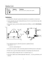
R<strong>an</strong>kine CycleReading Problems10-2 → 10-7 10-16, 10-34, 10-37, 10-44, 10-47, 10-59Definitions• working fluid is alternately vaporized <strong>an</strong>d condensed as it recirculates in a closed cycle• water is typically used as the working fluid because of its low cost <strong>an</strong>d relatively large valueof enthalpy of vaporization• the st<strong>an</strong>dard vapour cycle that excludes internal irreversibilities is called the <strong>Ideal</strong> R<strong>an</strong>kineCycle• the condensation process is allowed to proceed to completion betweenstate points 4 → 1– provides a saturated liquid at 1• the water at state point 1 c<strong>an</strong> be conveniently pumped to the boiler pressure at state point 2• but the water is not at the saturation temperature corresponding to the boiler pressure• heat must be added to ch<strong>an</strong>ge the water at 2 to saturated water at ‘a’• when heat is added at non-const<strong>an</strong>t temperature (between 2 − a), the cycle efficiency willdecrease1
<strong>An</strong>alyze the <strong>Process</strong>Assume steady flow, KE = PE =0.From a 1st law bal<strong>an</strong>ce, we knowenergy in = energy outDevice1st Law Bal<strong>an</strong>ceBoiler h 2 + q H = h 3 ⇒ q H = h 3 − h 2 (in)Turbine h 3 = h 4 + w T ⇒ w T = h 3 − h 4 (out)Condenser h 4 = h 1 + q L ⇒ q L = h 4 − h 1 (out)Pump h 1 + w P = h 2 ⇒ w P = h 2 − h 1 (in)The net work output is given asw T − w p = (h 3 − h 4 ) − (h 2 − h 1 )= (h 3 − h 4 )+(h 1 − h 2 )The net heat supplied to the boiler isq H =(h 3 − h 2 )The R<strong>an</strong>kine efficiency isη R =net work outputheat supplied to the boiler= (h 3 − h 4 )+(h 1 − h 2 )(h 3 − h 2 )2
If we consider the fluid to be incompressible(h 2 − h 1 )=v(P 2 − P 1 )Since the actual process is irreversible, <strong>an</strong> isentropic efficiency c<strong>an</strong> be defined such thatExp<strong>an</strong>sion process ⇒ <strong>Isentropic</strong> efficiency =actual workisentropic workisentropic workCompression process ⇒ <strong>Isentropic</strong> efficiency =actual workBoth isentropic efficiencies will have a numerical value between 0 <strong>an</strong>d 1.Effects of Boiler <strong>an</strong>d Condenser PressureWe know the efficiency is proportional toη ∝ 1 − T LT HThe question is → how do we increase efficiency ⇒ T L ↓ <strong>an</strong>d/or T H ↑.1. INCREASED BOILER PRESSURE:• <strong>an</strong> increase in boiler pressure results in a higher T H <strong>for</strong> the same T L , there<strong>for</strong>e η ↑.• but 4 ′ has a lower quality th<strong>an</strong> 4– wetter steam at the turbine exhaust3
2. LOWER T L :– results in cavitation of the turbine blades– η ↓ plus ↑ mainten<strong>an</strong>ce• quality should be > 80% at the turbine exhaust• we are generally limited by the TER(lake, river, etc.)eg. lake @ 15 ◦ C +ΔT } =10 {{ ◦ C}=25 ◦ Cresist<strong>an</strong>ce to HT⇒ P sat =3.2 kP a.• this is why we have a condenser– the pressure at the exit of the turbine c<strong>an</strong> be less th<strong>an</strong> atmospheric pressure– the closed loop of the condenser allows us to use treated water on the cycle side– but if the pressure is less that atmospheric pressure, air c<strong>an</strong> leak into the condenser,preventing condensation3. INCREASED T H BY ADDING SUPERHEAT:• the average temperature at which heat is supplied in the boiler c<strong>an</strong> be increased bysuperheating the steam– dry saturated steam from the boiler is passed through a second b<strong>an</strong>k of smallerbore tubes within the boiler until the steam reaches the required temperatureThe adv<strong>an</strong>tage isη = W net ↑Q H ↑overall ↑The value of T H , the me<strong>an</strong> temperature at which heat is added, increases, whileT L remains const<strong>an</strong>t. There<strong>for</strong>e the efficiency increases.– the quality of the turbine exhaust increases, hopefully where x>0.9– with sufficient superheating the turbine exhaust c<strong>an</strong> fall in the superheated region.4
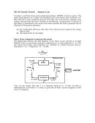
R<strong>an</strong>kine Cycle with Reheat• the wetness at the exhaust of the turbine should be no greater that 10% - this c<strong>an</strong> result inphysical erosion of the turbine blades• but high boiler pressures are required <strong>for</strong> high efficiency - tends to lead to a high wetnessratio• to improve the exhaust steam conditions, the steam c<strong>an</strong> be reheated with the exp<strong>an</strong>sion carriedout in two stepsTQHQRHSteamGeneratorQHHigh PressureTurbineQRHLow PressureTurbineWTsWPQCondenserPumpL• the temperature of the steam entering the turbine is limited by metallurgical constraints• modern boilers c<strong>an</strong> h<strong>an</strong>dle up to 30 MPa <strong>an</strong>d a maximum temperature ofT max ≈ 650 ◦ C.• newer materials, such as ceramic blades c<strong>an</strong> h<strong>an</strong>dle temperatures up to 750 ◦ C.5
R<strong>an</strong>kine Cycle with Regeneration• Carnot cycle has efficiency:η =1− T L /T H– add Q H at as high a T H as possible– reject Q L at as low a T L as possible• the R<strong>an</strong>kine cycle c<strong>an</strong> be used with a Feedwater Heater to heat the high pressure sub-cooledwater at the pump exit to the saturation temperature– most of the heat addition (Q H ) is done at high temperatureFeedwater HeatersThere are two different types of feedwater heaters1. OPEN FWH: the streams mix → high temperature steam with low temperature water atconst<strong>an</strong>t pressure2. CLOSED FWH: a heat exch<strong>an</strong>ger is used to tr<strong>an</strong>sfer heat between the two streams but thestreams do not mix. The two streams c<strong>an</strong> be maintained at different pressures.6
1. OPEN FWH:• working fluid passes isentropically through the turbine stages <strong>an</strong>d pumps• steam enters the first stage turbine at state 1 <strong>an</strong>d exp<strong>an</strong>ds to state 2 - where a fractionof the total flow is bled off into <strong>an</strong> open feedwater heater at P 2• the rest of the steam exp<strong>an</strong>ds into the second stage turbine at state point 3 - this portionof the fluid is condensed <strong>an</strong>d pumped as a saturated liquid to the FWH at P 2• a single mixed stream exists the FWH at state point 6<strong>An</strong>alysis:• we must determine the mass flow rates through each of the components.By per<strong>for</strong>ming <strong>an</strong> mass bal<strong>an</strong>ce over the turbineṁ 6 + ṁ 7 = ṁ 5 (1)If we normalize Eq. (1) with respect the total mass flow rate ṁ 1ṁ 6+ ṁ7= 1 (2)ṁ 5 ṁ 5Let the flow at state point 2 bey =ṁ6ṁ 5There<strong>for</strong>eṁ 7=1− y (3)ṁ 5Assuming no heat loss at the FWH, establish <strong>an</strong> energy bal<strong>an</strong>ce across the FWHyh 6 +(1− y)h 2 =1· h 3<strong>an</strong>dy = h 3 − h 2h 6 − h 2=ṁ6ṁ 51 − y = ṁ7ṁ 57
2. CLOSED FWH:• two variations exist(a) pump the condensate back to the high pressure line(b)– a steam trap is inserted in the condensed steam line that allows only liquid topass– liquid is passed to a low pressure region such as the condenser or a low pressureheater• the incoming feedwater does not mix with the extracted steam– both streams flow separately through the heater– the two streams c<strong>an</strong> have different pressures8
Other Topics“IDEAL” RANKINE CYCLE:• too expensive to build• requires multiple reheat <strong>an</strong>d regeneration cycles• approaches Carnot efficiencyTOPPING CYCLE (BINARY CYCLE):• involves two R<strong>an</strong>kine cycles running in t<strong>an</strong>dem with different working fluids such asmercury <strong>an</strong>d water• why:– typically a boiler will supply energy at 1300 − 1400 ◦ C– but T critical <strong>for</strong> water is 374.14 ◦ C∗ most energy is absorbed below this temperature∗ high ΔT between the boiler source <strong>an</strong>d the water leads to a major source ofirreversibilities– T critical <strong>for</strong> mercury is about 1500 ◦ C∗ no need <strong>for</strong> superheating– combine the large enthalpy of evaporation of water at low temperatures with theadv<strong>an</strong>tages of mercury at high temperatures– in addition, the mercury dome leads to a high quality at the exit of the turbine9
Refrigeration CycleReadingProblems11-1 → 11-7, 11-9 11-11, 11-44, 11-47, 11-104Definitions• a refrigeration system removes thermal energy from a low-temperature region <strong>an</strong>d tr<strong>an</strong>sfersheat to a high-temperature region.• the 1st law of thermodynamics tells us that heat flow occurs from a hot source to a coolersink, there<strong>for</strong>e, energy in the <strong>for</strong>m of work must be added to the process to get heat to flowfrom a low temperature region to a hot temperature region.• refrigeration cycles may be classified as– vapour compression– gas compression• we will examine only the vapour compression systems• refrigerators <strong>an</strong>d heat pumps have a great deal in common. The primary difference is in them<strong>an</strong>ner in which heat is utilized.– Refrigerator ↓ C} {{ }takes heat from→H }{{}tr<strong>an</strong>sf ers to– Heat Pump C }{{}takes heat from• this is simply a ch<strong>an</strong>ge in view point→H ↑} {{ }tr<strong>an</strong>sf ers to• the Carnot cycle c<strong>an</strong> serve as the initial model of the ideal refrigeration cycle.– operates as a reversed heat engine cycle - tr<strong>an</strong>sfers a qu<strong>an</strong>tity of heat, Q L , from a coldsource at temperature, T LQ L = T L (s 3 − s 2 )Q H = T H (s 4 − s 1 )1
W in = Q net = Q H − Q L= (T H − T L )(s 3 − s 2 )The coefficient of per<strong>for</strong>m<strong>an</strong>ce (COP) is given byCOP = benefitcostwhere the benefit <strong>for</strong> a refrigeration process is the cooling load given as Q L . This is the net benefit,i.e. heat is removed from the cold space. For a heat pump, the benefit is the heat added to the hotspace, i.e. Q H .COP refrig = Q LW in=T LT H − T LCOP heat pump = Q HW in=T HT H − T LNote:COP heat pump =T HT H − T L= (T H − T L )+T LT H − T L=T LT H − T L+1= COP refrig +1The “1” accounts <strong>for</strong> the sensible heat addition in going from T L to T H .2
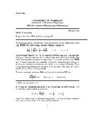
Vapour Compression Refrigeration CycleRoom Airsat. liquidQHCondensersuperheatedvapourExp<strong>an</strong>sionValveh = h 3compressorgas4LEvaporator2 phase sat. vapourQFoodAssumptions <strong>for</strong> <strong>Ideal</strong> VCRC• irreversibilities within the evaporator, condenser <strong>an</strong>d compressor are ignored• no frictional pressure drops• refriger<strong>an</strong>t flows at const<strong>an</strong>t pressure through the two heat exch<strong>an</strong>gers (evaporator <strong>an</strong>d condenser)• stray heat losses to the surroundings are ignored• compression process is isentropic3
Refrigeration <strong>Process</strong><strong>Process</strong>1-2s:2s-3:DescriptionA reversible, adiabatic (isentropic) compression of the refriger<strong>an</strong>t.The saturated vapour at state 1 is superheated to state 2.⇒ w c = h 2s − h 1<strong>An</strong> internally, reversible, const<strong>an</strong>t pressure heat rejectionin which the working subst<strong>an</strong>ce is desuperheated <strong>an</strong>d then condensedto a saturated liquid at 3. During his process, the working subst<strong>an</strong>cerejects most of its energy to the condenser cooling water.⇒ q H = h 2s − h 33-4 <strong>An</strong> irreversible throttling process in which the temperature <strong>an</strong>dpressure decrease at const<strong>an</strong>t enthalpy.⇒ h 3 = h 44-1 <strong>An</strong> internally, reversible, const<strong>an</strong>t pressure heat interactionin which the working fluid is evaporated to a saturated vapourat state point 1. The latent enthalpy necessary <strong>for</strong> evaporationis supplied by the refrigerated space surrounding the evaporator.The amount of heat tr<strong>an</strong>sferred to the working fluid in the evaporatoris called the refrigeration load.⇒ q L = h 1 − h 4The thermal efficiency of the cycle c<strong>an</strong> be calculated asη = q evapw comp= h 1 − h 4h 2s − h 14
Common Refriger<strong>an</strong>tsThere are several fluorocarbon refriger<strong>an</strong>ts that have been developed <strong>for</strong> use in VCRC.R11R12 CCl 2 F 2 dichlorofluorometh<strong>an</strong>e- used <strong>for</strong> refrigeration systems at highertemperature levels- typically, water chillers <strong>an</strong>d air conditioningR22 CHClF 2 has less chlorine, a little better <strong>for</strong> theenvironment th<strong>an</strong> R12- used <strong>for</strong> lower temperature applicationsR134a CFH 2 CF3 tetrafluoreth<strong>an</strong>e - no chlorine- went into production in 1991- replacement <strong>for</strong> R12R141b C 2 H 3 FCl 2 dichlorofluoroeth<strong>an</strong>eAmmonia NH 3 corrosive <strong>an</strong>d toxic- used in absorption systemsR744 CO 2 behaves in the supercritical region-lowefficiencyR290 prop<strong>an</strong>e combustibleHow to Choose a Refriger<strong>an</strong>tM<strong>an</strong>y factors need to be considered• ozone depletion potential• global warming potential• combustibility• thermal factorsOzone Depletion Potential• chlorinated <strong>an</strong>d brominated refriger<strong>an</strong>ts• acts as a catalyst to destroy ozone molecules5
• reduces the natural shielding effect from incoming ultra violet B radiationGlobal Warming Potential• gases that absorb infrared energy• gases with a high number of carbon-fluorine bonds• generally have a long atmospheric lifetimeCombustibility• all hydro-carbon fuels, such as prop<strong>an</strong>eThermal Factors• the heat of vaporization of the refriger<strong>an</strong>t should be high. The higher h fg , the greater therefrigerating effect per kg of fluid circulated• the specific heat of the refriger<strong>an</strong>t should be low. The lower the specific heat, the less heatit will pick up <strong>for</strong> a given ch<strong>an</strong>ge in temperature during the throttling or in flow through thepiping, <strong>an</strong>d consequently the greater the refrigerating effect per kg of refriger<strong>an</strong>t• the specific volume of the refriger<strong>an</strong>t should be low to minimize the work required per kgof refriger<strong>an</strong>t circulated• since evaporation <strong>an</strong>d condenser temperatures are fixed by the temperatures of the surroundings- selection is based on operating pressures in the evaporator <strong>an</strong>d the condenser• selection is based on the suitability of the pressure-temperature relationship of the refriger<strong>an</strong>t• other factors include:– chemical stability– toxicity– cost– environmental friendliness– does not result in very low pressures in the evaporator (air leakage)– does not result in very high pressures in the condenser (refriger<strong>an</strong>t leakage)6
Designation Chemical Ozone Depletion Global WarmingFormula Potential 1 Potential 2Ozone Depleting & Global Warming ChemicalsCFC-11 CCl 3 F 1 3,400CFC-12 CCl 2 F 2 0.89 7,100CFC-13 CClF 3 13,000CFC-113 C 2 F 3 Cl 3 0.81 4,500CFC-114 C 2 F 4 Cl 2 0.69 7,000CFC-115 C 2 F 5 Cl 1 0.32 7,000Halon-1211 CF 2 ClBr 2.2-3.5Halon-1301 CF 3 Br 8-16 4,900Halon-2402 C 2 F 4 Br 2 5-6.2carbon tetrachloride CCl 4 1.13 1,300methyl chloro<strong>for</strong>m CH 3 Ccl 3 0.14nitrous oxide N 2 O 270Ozone Depleting & Global Warming Chemicals - Class 2HCFC-22 CHF 2 Cl 0.048 1,600HCFC-123 C 2 HF 3 Cl 2 0.017 90HCFC-124 C 2 HF 4 Cl 0.019 440HCFC-125 C 2 HF 5 0.000 3,400HCFC-141b C 2 H 3 FCl 2 0.090 580HCFC-142b C 2 H 3 F 2 Cl 0.054 1800Global Warming, non-Ozone Depleting Chemicalscarbon dioxide CO 2 0 1meth<strong>an</strong>e CH 4 0 11HFC-125 CHF 2 CF 3 0 90HFC-134a CFH 2 CF 3 0 1,000HFC-152a CH 3 CHF 2 0 2,400perfluorobut<strong>an</strong>e C 4 F 10 0 5,500perfluoropent<strong>an</strong>e C 5 F 12 0 5,500perfluorohex<strong>an</strong>e C 6 F 14 0 5,100perfluorotributylamine N(C 4 F 9 ) 3 0 4,3001 - relative to R112 - relative to CO 27
Cascade Refrigeration System• combined cycle arr<strong>an</strong>gements• two or more vapour compression refrigeration cycles are combined• used where a very wide r<strong>an</strong>ge of temperature between T L <strong>an</strong>d T H is required• the condenser <strong>for</strong> the low temperature refrigerator is used as the evaporator <strong>for</strong> the hightemperature refrigeratorAdv<strong>an</strong>tages• the refriger<strong>an</strong>ts c<strong>an</strong> be selected to have reasonable evaporator <strong>an</strong>d condenser pressures in thetwo or more temperature r<strong>an</strong>ges8
Absorption Refrigeration SystemDifferences between <strong>an</strong> absorption refrigeration system <strong>an</strong>d a VCRCVCRC• vapour is compressedbetween the evaporator <strong>an</strong>dthe condenser• process is driven by workAbsorption RS• the refriger<strong>an</strong>t is absorbed by<strong>an</strong> absorbent material to <strong>for</strong>m aliquid solution• heat is added to the processto retrieve the refriger<strong>an</strong>t vapourfrom the liquid solution• process is driven by heatAdv<strong>an</strong>tages• since the working fluid is pumped as a liquid the specific volume is less th<strong>an</strong> that of a gas (asin the VCRC compressor), hence the work input is much less.• there are considerable savings in power input because a pump is used instead of a compressor.• this is weighed off against the cost of extra hardware in <strong>an</strong> absorption systemCommon Refriger<strong>an</strong>t/Absorber CombinationsRefriger<strong>an</strong>tAbsorber1. ammonia water2. water lithium bromidelithium chloride9
<strong>Process</strong>liquidammoniaRoom AirQHCondenserammoniavapour onlySource ofHeatGeneratorQ*HExp<strong>an</strong>sionValveweak ammoniawater solutioncoldregeneratorEvaporatorAbsorber2 phase dry vapourQLQ*LFoodstrong ammoniacold water solutionsinkpump• ammonia circulates through the condenser, exp<strong>an</strong>sion valve <strong>an</strong>d evaporator (same as in theVCRC)• the compressor is replaced by <strong>an</strong> absorber, pump, generator, regenerator <strong>an</strong>d a valve• in the absorber, ammonia vapour is absorbed by liquid water– the process is exothermic (gives off heat)– ammonia vapour is absorbed into the water at low T <strong>an</strong>d P maintained by me<strong>an</strong>s ofQ ∗ L– absorption is proportional to 1/T ⇒ the cooler the better• the pump raises the solution to the pressure of the generator• in the generator, ammonia is driven out of the solution by the addition of Q ∗ H ,(endothermic reaction)• ammonia vapour is passed back to the condenser• a regenerator is used to recoup some of the energy from the weak ammonia water solutionpassed back to the absorber. This energy is tr<strong>an</strong>sferred to the solution pumped to the generator.This reduces the Q ∗ Hrequired to vapourize the solution in the generator. It also reducesthe amount of Q ∗ Lthat needs to be removed from the solution in the absorber.10
Internal Combustion EnginesReading Problems9-3 → 9-7 9-37, 9-41, 9-47, 9-51, 9-56Definitions1. spark ignition:• a mixture of fuel <strong>an</strong>d air is ignited by a spark plug• applications requiring power to about 225 kW (300 HP)• relatively light <strong>an</strong>d low in cost2. compression ignition engine:• air is compressed to a high enough pressure <strong>an</strong>d temperature that combustion occurswhen the fuel is injected• applications where fuel economy <strong>an</strong>d relatively large amounts of power arerequiredThe <strong>Gas</strong>oline Engine1
• conversion of chemical energy to mech<strong>an</strong>ical energy• c<strong>an</strong> obtain very high temperatures due to the short duration of the power strokeAir St<strong>an</strong>dard CycleASSUMPTIONS:• air is <strong>an</strong> ideal gas with const<strong>an</strong>t c p <strong>an</strong>d c v• no intake or exhaust processes• the cycle is completed by heat tr<strong>an</strong>sfer to the surroundings• the internal combustion process is replaced by a heat tr<strong>an</strong>sfer process from a TER• all internal processes are reversible• heat addition occurs inst<strong>an</strong>t<strong>an</strong>eously while the piston is at TDCDefinitionsMe<strong>an</strong> Effective Pressure (MEP): The theoretical const<strong>an</strong>t pressure that, if it acted on the pistonduring the power stroke would produce the same net work as actually developed in onecomplete cycle.MEP =net work <strong>for</strong> one cycledisplacement volume =W netV BDC − V TDCThe me<strong>an</strong> effective pressure is <strong>an</strong> index that relates the work output of the engine to it size(displacement volume).2
Otto Cycle• the theoretical model <strong>for</strong> the gasoline engine• consists of four internally reversible processes• heat is tr<strong>an</strong>sferred to the working fluid at const<strong>an</strong>t volumeThe Otto cycle consists of four internally reversible processes in series1 → 2 isentropic compression or air as the piston moves from BDC to TDC2 → 3 const<strong>an</strong>t volume heat addition to the fuel/air mixture from <strong>an</strong> external source while thepiston is at TDC (represents the ignition process <strong>an</strong>d the subsequent burning of fuel)3 → 4 isentropic exp<strong>an</strong>sion (power stroke)4 → 1 const<strong>an</strong>t volume heat rejection at BDC3
The Otto cycle efficiency is given asη =1− T ( ) k−1 ( ) 1−k1 V2V1=1− =1−T 2 V 1 V 2If we letr = V 1V 2= V 4V 3= compression ratioThenη Otto =1− r 1−kWhy not go to higher compression ratios?• there is <strong>an</strong> increased tendency <strong>for</strong> the fuel to detonate as the compression ratio increases• the pressure wave gives rise to engine knock• c<strong>an</strong> be reduced by adding tetraethyl lead to the fuel• not good <strong>for</strong> the environment4
Diesel Cycle• <strong>an</strong> ideal cycle <strong>for</strong> the compression ignition engine (diesel engine)• all steps in the cycle are reversible• heat is tr<strong>an</strong>sferred to the working fluid at const<strong>an</strong>t pressure• heat tr<strong>an</strong>sfer must be just sufficient to maintain a const<strong>an</strong>t pressureIf we letr = V 1V 2= compression ratio = V 4V 2r v = V 3V 2= cutoff ratio → injection periodthen the diesel cycle efficiency is given asη Diesel =1− 1 ( )( 1 rkv − 1 )r k−1 k r v − 15
Where we noteη Diesel =1− 1 ( )( 1 rkv − 1 )r k−1 k r v − 1} {{ }=1 in the Otto CycleComparison of the Otto <strong>an</strong>d the Diesel Cycle• η Otto >η Diesel <strong>for</strong> the same compression ratio• but a diesel engine c<strong>an</strong> tolerate a higher ratio since only air is compressed in a diesel cycle<strong>an</strong>d spark knock is not <strong>an</strong> issue• direct comparisons are difficultDual Cycle(Limited Pressure Cycle)• this is a better representation of the combustion process in both the gasoline <strong>an</strong>d the dieselengines• in a compression ignition engine, combustion occurs at TDC while the piston moves downto maintain a const<strong>an</strong>t pressure6
Dual Cycle EfficiencyGivenr = V 1V 2= compression ratior v = V 4V 3= cutoff ratior p = P 3P 2= pressure ratioη Dual =1−r p r k v − 1[(r p − 1) + kr p (r v − 1)] r k−1Note: if r p =1we get the diesel efficiency.7
Stirling Cycle8
• reversible regenerator used as <strong>an</strong> energy storage device• possible to recover all heat given up by the working fluid in the const<strong>an</strong>t volume coolingprocess• all the heat received by the cycle is at T H <strong>an</strong>d all heat rejected at T L• η Stirling =1− T L /T H(Carnot efficiency)With perfect regenerationQ H = T H (s 2 − s 1 )Q L = T L (s 3 − s 4 )9
η = W netQ H= Q H − Q LQ H=1− Q LQ H=1− T L(s 3 − s 4 )T H (s 2 − s 1 )(1)From Gibb’s equationTds = du + Pdv = c v dT + Pdvif T = const<strong>an</strong>t ⇒ Tds = Pdv ⇒ ds = PdvIntegrating givesT= Rdvvs 3 − s 4 = R ln( ) ( )v3v2= R ln = s 2 − s 1v 4 v 1There<strong>for</strong>e s 3 − s 4 = s 2 − s 1 , <strong>an</strong>d Eq. 1 givesη =1− T LT H⇒ Carnot efficiency10
Brayton CycleReading Problems9-8 → 9-10 9-78, 9-84, 9-108Open Cycle <strong>Gas</strong> Turbine Engines• after compression, air enters a combustion chamber into which fuel is injected• the resulting products of combustion exp<strong>an</strong>d <strong>an</strong>d drive the turbine• combustion products are discharged to the atmosphere• compressor power requirements vary from 40-80% of the power output of the turbine (remainderis net power output), i.e. back work ratio = 0.4 → 0.8• high power requirement is typical when gas is compressed because of the large specificvolume of gases in comparison to that of liquids<strong>Ideal</strong>ized Air St<strong>an</strong>dard Brayton Cycle• closed loop• const<strong>an</strong>t pressure heat addition <strong>an</strong>d rejection• ideal gas with const<strong>an</strong>t specific heats1
Brayton Cycle EfficiencyThe Brayton cycle efficiency c<strong>an</strong> be written asη =1− (r p ) (1−k)/kwherewedefine the pressure ratio as:r p = P 2P 1= P 3P 42
Maximum Pressure RatioGiven that the maximum <strong>an</strong>d minimum temperature c<strong>an</strong> be prescribed <strong>for</strong> the Brayton cycle, ach<strong>an</strong>ge in the pressure ratio c<strong>an</strong> result in a ch<strong>an</strong>ge in the work output from the cycle.The maximum temperature in the cycle (T 3 ) is limited by metallurgical conditions because theturbine blades c<strong>an</strong>not sustain temperatures above 1300 K. Higher temperatures (up to 1600 K c<strong>an</strong>be obtained with ceramic turbine blades). The minimum temperature is set by the air temperatureat the inlet to the engine.3
Brayton Cycle with Reheat• T 3 is limited due to metallurgical constraints• excess air is extracted <strong>an</strong>d fed into a second stage combustor <strong>an</strong>d turbine• turbine outlet temperature is increased with reheat (T 6 >T ′ 4), there<strong>for</strong>e potential <strong>for</strong> regenerationis enh<strong>an</strong>ced• when reheat <strong>an</strong>d regeneration are used together the thermal efficiency c<strong>an</strong> increase signific<strong>an</strong>tly4
Compression with Intercooling• the work required to compress in a steady flow device c<strong>an</strong> be reduced by compressing instages• cooling the gas reduces the specific volume <strong>an</strong>d in turn the work required <strong>for</strong> compression• by itself compression with intercooling does not provide a signific<strong>an</strong>t increase in the efficiencyof a gas turbine because the temperature at the combustor inlet would require additionalheat tr<strong>an</strong>sfer to achieve the desired turbine inlet temperature• but the lower temperature at the compressor exit enh<strong>an</strong>ces the potential <strong>for</strong> regeneration i.e.a larger ΔT across the heat exch<strong>an</strong>ger5
Brayton Cycle with Regeneration• a regenerator (heat exch<strong>an</strong>ger) is used to reduce the fuel consumption to provide the required˙Q H• the efficiency with a regenerator c<strong>an</strong> be determined as:η =Ẇnet˙Q H= 1 − ˙Q L˙Q H6
= 1 − c p(T 6 − T 1 )c p (T 3 − T 5 )= 1 − c p(T ′ 6 − T 1)c p (T 3 − T ′ 5 )⇒ (<strong>for</strong> a real regenerator)⇒ (<strong>for</strong> <strong>an</strong> ideal regenerator)= 1 − c p(T 2 − T 1 )c p (T 3 − T 4 )<strong>an</strong>dη =1−( )Tmin(r p ) (k−1)/kT max• <strong>for</strong> a given T min /T max , the use of a regenerator above a certain r p will result in a reductionof ηwith <strong>an</strong> idealregeneratorwithout aregeneratorbetter with aregeneratorbetter withouta regeneratorT / T = 0.25T / T = 0.3131T / T = 0.2313rp, crrp7
Regenerator Effectivenessɛ =˙Q reg,actual˙Q reg,ideal= h 5 − h 2h ′ 5 − h 2= h 5 − h 2h 4 − h 2= T 5 − T 2T 4 − T 2Typical values of effectiveness are ≤ 0.7Repeated intercooling, reheating <strong>an</strong>d regeneration ( will provide a system that approximates theEricsson Cycle which has Carnot efficiency η =1− T )L.T HBrayton Cycle With Intercooling, Reheating <strong>an</strong>d Regeneration8
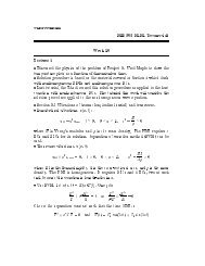
TTmaxQHQH, RQreg7sQ9sreg4s2sTminQL, IQLsCompressor <strong>an</strong>d Turbine Efficiencies<strong>Isentropic</strong> Efficiencies(1) η comp = h 2,s − h 1= c p(T 2,s − T 1 )h 2 − h 1 c p (T 2 − T 1 )(2) η turb = h 3 − h 4h 3 − h 4,s= c p(T 3 − T 4 )c p (T 3 − T 4,s )(3) η cycle = W netQ H= Q H − Q LQ H=1− Q L=1− c p(T 4 − T 1 )Q H c p (T 3 − T 2 )Given the turbine <strong>an</strong>d compressor efficiencies <strong>an</strong>d the maximum (T 3 ) <strong>an</strong>d the minimum (T 1 ) temperaturesin the process, find the cycle efficiency (η cycle ).(4) Calculate T 2s from the isentropic relationship,( )T (k−1)/k2,s P2=.T 1 P 1Get T 2 from (1).(5) Do the same <strong>for</strong> T 4 using (2) <strong>an</strong>d the isentropic relationship.(6) substitute T 2 <strong>an</strong>d T 4 in (3) to find the cycle efficiency.9
Jet PropulsionReading Problems9-11 9-117, 9-121<strong>Gas</strong> Turbines <strong>for</strong> Aircraft Propulsion• gas turbines are well suited to aircraft propulsion because of their favorable power-to-weightratio• the exhaust pressure of the turbine will be greater th<strong>an</strong> that of the surroundings• gases are exp<strong>an</strong>ded in the turbine to a pressure where the turbine work is just equal to thecompressor work plus some auxiliary power <strong>for</strong> pumps <strong>an</strong>d generators i.e. the net workoutput is zero• since the gases leave at a high velocity, the ch<strong>an</strong>ge in momentum that the gas undergoesprovides a thrust to the aircraft• typically operate at higher pressure ratios, often in the r<strong>an</strong>ge of 10 to 25Conservation of Momentumwhere v ∗ iis the velocity of the aircraftd(Mom) x,cvdt=(Ṁom) x,in − (Ṁom) x,out + ∑ F x<strong>for</strong> steady flow ⇒ d dt =0<strong>an</strong>d 1
ṁ i v ∗ i − ṁ ev ∗ e + F T + P i A i − P e A e =0Since the air-fuel mass ratio is highṁ fuel
Turbojet EngineSections• a-1: diffuser– decelerates the incoming flow relative to the engine– a pressure rise known as a ram effect occurs, v ∗ (↓), P (↑)• 1-4: gas generator– compressor, combustor <strong>an</strong>d turbine∗ 1-2: isentropic compression∗ 2-3: const<strong>an</strong>t pressure heat addition∗ 3-4: isentropic exp<strong>an</strong>sion through the turbine during which work is developed– turbine power just enough to drive the compressor– air <strong>an</strong>d fuel are mixed <strong>an</strong>d burned in the combustion chamber at const<strong>an</strong>t pressure– P T >> P atm• 4-5: nozzle– isentropic exp<strong>an</strong>sion through the nozzle, air accelerates <strong>an</strong>d the pressure deceases– gases leave the turbine signific<strong>an</strong>tly higher in pressure th<strong>an</strong> atmospheric pressure– gases are exp<strong>an</strong>ded to produce a high velocity, v ∗ e >> v∗ iresults in a thrust– v ∗ 1
Afterburner• similar to a reheat device• produces a higher temperature at the nozzle inlet, T 5 >T 4• results in <strong>an</strong> increase in velocity4
By per<strong>for</strong>ming a 1st law energy over the nozzle we c<strong>an</strong> obtain <strong>an</strong> expression <strong>for</strong> the exit velocityin terms of the entr<strong>an</strong>ce temperature to the nozzle.dE↗ 0dt⎧ ⎡⎤⎫{]}⎪⎨= ˙Q↗ 0 +Ẇ↗ 0 + ṁ ⎢⎣ h 4 + (v∗ 4 )2⎪⎬⎥ − ṁ[h2 ⎦e + (v∗ e )2⎪⎩} {{ }2⎪⎭→ 0If we assume that the air velocity leaving the turbine is relatively small, the kinetic energy term at4 c<strong>an</strong> be assumed to go to zero <strong>an</strong>d we getv ∗ e==√2(h 4 − h e )√2c p (T 4 − T e )• exit velocity proportional to v ∗ e ∝ √ 2c p (T 4 − T e )• afterburner is used to increase T 4 to T 5• similar to a reheat device• produces a higher temperature at the nozzle inlet5
Other Types of Engines1. Turbo-Prop Engine• gas turbine drives the compressor <strong>an</strong>d the propeller• most of the thrust is from the propeller• works by accelerating large volumes of air to moderate velocities• propellers are best suited <strong>for</strong> low speed (< 300 mph) flight• new turbo-props are suitable <strong>for</strong> velocities up to 500 mph• by-pass ratio of 100:1 or more• by-pass ratio defined as:bypass ratio =mass flow bypassing the combustion chambermass flow through the combustion chamber6
2. Turbo-F<strong>an</strong> Engine (Ducted Turbo-Prop Engine)• best choice <strong>for</strong> fuel economy <strong>an</strong>d speed• high speed exhaust gases are mixed with the lower speed air in the by-pass resulting ina considerable noise reduction• by-pass ratio c<strong>an</strong> be adjusted• by-pass provides thrust <strong>for</strong> takeoff• the core provides thrust <strong>for</strong> cruising• typically used <strong>for</strong> speeds up to 600 mph• increasing the by-pass ratio results in increased thrust• typical by-pass ratios are 5-67
3. Ramjet• no moving parts• compression is achieved by decelerating the high-speed incoming air in the diffuser• aircraft must already be in flight at a high speed• used in aircraft flying above Mach 14. Pulse Jet Engine• similar to a ram jet but lets in a slug of air at a time <strong>an</strong>d then closes a damper duringthe combustion stage• uses a shutter-type valve <strong>for</strong> damper control• c<strong>an</strong> be used effectively at low velocities• used in Germ<strong>an</strong> V1 missle• the combustion firing rate was approximately 40 cycles/sec with a maximum flightvelocity of 600 mph8
Non-Reacting <strong>Gas</strong> MixturesReading Problems13-1 → 13-3 13-52, 13-6014-1 → 14-7 14-32, 14-35, 14-68, 14-71, 14-7514-79, 14-103, 14-112Introduction• homogeneous gas mixtures are frequently treated as a single compound rather th<strong>an</strong> m<strong>an</strong>yindividual constituents• the individual properties of inert gases tend to be submerged, such that the gas behaves as asingle pure subst<strong>an</strong>ce• eg. - air consists of oxygen, nitrogen, argon <strong>an</strong>d water vapour. But dry air c<strong>an</strong> be treated asa simple gas with a molar mass of 28.97 kg/kmole• equations c<strong>an</strong> be derived to express the properties of mixtures in terms of the properties oftheir individual constituents• it is assumed that each constituent is unaffected by the other constituents in the mixtureP-V-T Relationships <strong>for</strong> <strong>Ideal</strong> <strong>Gas</strong> MixturesAmagat Model (law of additive volumes)• the volume of a mixture is the sum of the volumes that each constituent gas would occupy ifeach were at the pressure, P <strong>an</strong>d temperature, T , of the mixtureT,P T,P T,Pm A m B remove m C = m A + m Bn A n B → n C = n A + n BV A V B partition V C = V A + V B• the volume that n i moles of a component i would occupy at P <strong>an</strong>d T is called the partialvolume, V iV i = n iRTP1
The volume of the gas mixture is equal to the sum of the volumes each gas would occupy if it existedat the mixture temperature <strong>an</strong>d pressure.j∑V = V ii=1Dalton Model (law of additive pressures)• the pressure of a mixture of gases is the sum of the pressures of its components when eachalone occupies the volume of the mixture, V , at the temperature, T , of the mixtureV, T V, T V, Tm A ,n A ,P A + m B ,n B ,P B = m C = m A + m Bn C = n A + n BP C = P A + P B• <strong>for</strong> a mixture of ideal gases the pressure is the sum of the partial pressures of the individualcomponentsThe pressure of a gas mixture is equal to the sum of the pressures each gas would exert if it existedalone at T <strong>an</strong>d V .By combining the results of the Amagat <strong>an</strong>d Dalton models i.e. (1) <strong>an</strong>d (2), we obtain <strong>for</strong> ideal gas mixturesP iP = V iV = n inThere<strong>for</strong>e, Amagat’s law <strong>an</strong>d Dalton’s law are equivalent to each other if the gases <strong>an</strong>d the mixtureare ideal gases.2
Mixture PropertiesExtensive properties such as U, H, c p ,c v <strong>an</strong>d S c<strong>an</strong> be found by adding the contribution of eachcomponent at the condition at which the component exists in the mixture.U = ∑ U i = ∑ m i u i = m ∑ X i u i = mu= ∑ n i u i = n ∑ Y i u i = nuwhere u is the specific internal energy of the mixture per mole of the mixture.u = ∑ X i u ih = ∑ X i h ic v = ∑ X i c vic p = ∑ X i c pis = ∑ X i s iCh<strong>an</strong>ges in internal energy <strong>an</strong>d enthalpy of mixturesu 2 − u 1 = ∑ X i (u 2 − u 1 ) i =h 2 − h 1 = ∑ X i (h 2 − h 1 ) i =∫ T2T 1c v dT = c v (T 2 − T 1 )∫ T2T 1c p dT = c p (T 2 − T 1 )s 2 − s 1 = ∑ X i (s 2 − s 1 ) i = c p ln T 2T 1− R ln P 2P 1These relationships c<strong>an</strong> also be expressed on a per mole basis.Entropy Ch<strong>an</strong>ge Due to Mixing of <strong>Ideal</strong> <strong>Gas</strong>es• when ideal gases are mixed, a ch<strong>an</strong>ge in entropy occurs as a result of the increase in disorderin the systems• if the initial temperature of all constituents are the same <strong>an</strong>d the mixing process is adiabatic3
– temperature does not ch<strong>an</strong>ge– but entropy doesΔS = −(m A R A ln P AP+ m BR B ln P BP + ···)j∑= − m i R i ln P ii=1 P= −Rj∑i=1n i ln Y i4
Psychrometrics• studies involving mixtures of dry air <strong>an</strong>d water vapour• used in the design of air-conditioning systems, cooling towers <strong>an</strong>d most processes involvingthe control of vapour content in air• <strong>for</strong> T ≤ 50 ◦ C (P sat ≤ 13 kP a) ⇒ h ≈ h(T )– water vapour c<strong>an</strong> be treated as <strong>an</strong> ideal gasDefinitionsMoist Air• a mixture of dry air <strong>an</strong>d water vapour where dry air is treated as if it were a pure component• the overall mixture is given as ⇒ P = mRTVTotal PressureP = P a + P wP a = m aR a TVP w = m wR w TVwhere P a is the partial pressure of air <strong>an</strong>d P w is the partial pressure of water vapour. Typicallym w
= ˜M w n w˜M a n a= ˜M w (P w V/RT )˜M a (P a V/RT )=⎛ ˜ ⎞ ( )M⎝ w Pw⎠˜M a P a= 0.622(PwP a)In addition ω c<strong>an</strong> be written asω =0.622(PwP a)=0.622(PwP − P w)=0.622(φPsatP − φP sat)which c<strong>an</strong> be rearr<strong>an</strong>ged in terms of relative humidityφ =PωP sat⎛⎝ω +˜M⎞w⎠˜M a=PωP sat (ω +0.622)Dry Bulb Temperature - the temperature measured by a thermometer placed in a mixture of air<strong>an</strong>d water vapourWet Bulb Temperature6
• thermometer surrounded by a saturated wick• if air/water vapour mixture is not saturated, some water in the wick evaporates <strong>an</strong>d diffusesinto the air → cooling the water in the wick• as the temperature of the water drops, heat is tr<strong>an</strong>sferred to the water from both the air <strong>an</strong>dthe thermometer• the steady state temperature is the wet-bulb temperatureSling Psychrometer - a rotating set of thermometers one of which measures wet bulb temperature<strong>an</strong>d the other dry bulb temperature. T DB <strong>an</strong>d T WB are sufficient to fix the state of the mixture.The Psychrometric Chartwhere the dry bulb temperature is the temperature measured by a thermometer place in the mixture<strong>an</strong>d the wet bulb temperature is the adiabatic saturation temperature.7
<strong>An</strong> Adiabatic SaturatorHow c<strong>an</strong> we measure humidity?• the adiabatic saturator is used to measure humidity• two inlets, single exit device through which moist air passes• air-water mixture of unknown humidity enters at a known pressure <strong>an</strong>d temperature• if air/water mixture is not saturated, (φ
By definitionω 1 =(ṁwṁ a)1(4)ω 3 =(ṁwṁ a)3(5)From (2) <strong>an</strong>d (1)) (ṁw,2=ṁ a,1⎛ ⎞ṁ w,3−⎜⎝ ṁ a,1⎟} {{ }⎠ṁ a,3) (ṁw,1= ω 3 − ω 1ṁ a,1Dividing (3) by ṁ a,1 <strong>an</strong>d noting m a1 = m a3 <strong>an</strong>d m w 2m a1= ω 3 − ω 1h a,1 + ω 1 h w,1 +(ω 3 − ω 1 ) h w,2 = h a,3 + ω 3 h w,3 (6)ω 1 = (h a,3 − h a,1 )+ω 3 (h w,3 − h w,2 )(h w,1 − h w,2 )9
If we assume:i) air is <strong>an</strong> ideal gas <strong>an</strong>d (h a,3 − h a,1 )=c pa (T 3 − T 1 )ii) (h w,3 − h w,2 )=h g − h f = h fg (T 3 )iii) h w,1 ≈ h g (T 1 )iv) h w,2 = h f (T 2 )=h f (T 3 )then we c<strong>an</strong> write ω 1 as a function of T 1 <strong>an</strong>d T 3 onlyω 1 = c p a(T 3 − T 1 )+ω 3 h fg (T 3 )h g (T 1 ) − h f (T 3 )Aside: Since h f
Reacting <strong>Gas</strong> MixturesReading Problems15-1 → 15-7 15-21, 15-32, 15-51, 15-61, 15-7415-83, 15-91, 15-93, 15-98Introduction• thermodynamic <strong>an</strong>alysis of reactive mixtures is primarily <strong>an</strong> extension of the principles wehave learned thus far• it is necessary to modify the methods used to calculate specific enthalpy, internal energy <strong>an</strong>dentropyDefinitionsCombustion <strong>Process</strong>:• a fuel made up of hydrocarbons is said to have burned completely if:– all the carbon present in the fuel is burned to carbon dioxide– all the hydrogen is burned to water• if the conditions are not fulfilled the combustion process is incompleteCombustion Reactions:react<strong>an</strong>ts → productsorfuel + oxidizer → products• in all cases the mass is conservedmass of products = mass of react<strong>an</strong>tsFuels:• fuel is simply a combustible subst<strong>an</strong>ce• hydrocarbon fuels exist as liquids, gases <strong>an</strong>d solids– liquids → gasoline - oct<strong>an</strong>e, C 8 H 181
– gases → meth<strong>an</strong>e, CH 4– solids → coalCombustion Air:• oxygen is required in every combustion reaction• in most combustion reactions air provides the needed oxygen• dry air is considered to be21% oxygen79% nitrogen}on a molar basismolar ratio = n N 2= 0.79n O2 0.21 =3.761 mole of air c<strong>an</strong> then be written as [0.21 O 2 + 0.79 N 2 ]For convenience, we typically refer to air as [O 2 + 3.76 N 2 ] which is actually 4.76moles of air.Note: From the Amagat model, we know that a mixture at a known T <strong>an</strong>d P (as is thecase with combustion reactions)n in = V iVThere<strong>for</strong>e, by expressing a mixture in terms of the number of moles we are also expressingit in terms of a volume fraction.• nitrogen does not undergo a chemical reaction in combustion since it is inertAir-Fuel Ratio:where:mass of airmass of fuel =AF =¯ AF⎛⎝˜M⎞air⎠˜M fuelmoles of air × ˜M airmoles of fuel × ˜M fuelAFAF- air fuel ratio on a mass basis- air fuel ratio on a molar basis˜M air= 28.97 kg/kmole2
Theoretical or Stoichiometric Air:• the minimum amount of air that supplies sufficient oxygen <strong>for</strong> complete combustion ofall carbon <strong>an</strong>d hydrogen in the fuel - referred to as stoichiometric, 100% stoichiometricor theoretical• no free oxygen would appear in the products• greater th<strong>an</strong> stoichiometric leads to free oxygen in the products• less th<strong>an</strong> stoichiometric <strong>an</strong>d C, CO, OH, H 2 will appear in the products since there isnot enough oxygen to <strong>for</strong>m water or carbon dioxide (the actual proportions will dependon the temperature <strong>an</strong>d the pressure)• normally the amount of air supplied is given as a percentage of the theoretical valuei.e. 150% = 1.5 × the theoretical air- referred to as 20% excess air, 120% stoichiometricEquivalence Ratio:• defined asequivalence ratio =AF actualAF theoretical• if the equivalence ratio is:– > 1 → le<strong>an</strong> mixture (excess air)– < 1 → rich mixture (not enough air)3
Conservation of Energy <strong>for</strong> Reacting SystemsEnthalpy of Formation• previous calculations involving enthalpy were all based on differences <strong>an</strong>d the reference usedto determine enthalpy did not matter• when chemical reactions occur, react<strong>an</strong>ts disappear <strong>an</strong>d products are <strong>for</strong>med→ differences c<strong>an</strong>not be calculated <strong>for</strong> all subst<strong>an</strong>ces involved• it is necessary to establish a common base to account <strong>for</strong> differences in composition• the enthalpy datum <strong>for</strong> reacting systems is set to zero at st<strong>an</strong>dard temperature <strong>an</strong>d pressure– T ref =25 ◦ C → 298 K– P ref =1atm• h =0assigned to elements in their most stable <strong>for</strong>m i.e. O 2 ,N 2 , C, etc.• Enthalpy of Formation: the energy released or absorbed when a compound is <strong>for</strong>med fromits stable elements at STPwhere h o fis the enthalpy of <strong>for</strong>mation.Taking <strong>an</strong> energy bal<strong>an</strong>ce over the combustion chamber shown above, we obtaina h o A + b ho B + c ho C} {{ }generally=0+ h o f −→ ho ABCThe left side of the equation is typically zero because h =0<strong>for</strong> elements in their stable<strong>for</strong>m. The sign of h o findicates the direction of heat flow; +ve is endothermic <strong>an</strong>d -ve isexothermic.4
Effects of Non-St<strong>an</strong>dard Temperatureh(T,P)=h o f +(h T,P − h o T =25 ◦ C, P =1atm )} {{ }Δh at known temperatureswhereh o fis the heat resulting from a chemical ch<strong>an</strong>ge at T =25 ◦ C <strong>an</strong>d P =1atmΔhis the heat resulting from a ch<strong>an</strong>ge in temperature (sensible heat) with respectto the reference temperature, T ref =25 ◦ C5
Enthalpy of Combustion• while the enthalpy of <strong>for</strong>mation is related to elemental react<strong>an</strong>ts −→ resulting in a singlecompound; the enthalpy of combustion is related to fuel + oxidizer as the react<strong>an</strong>ts• Enthalpy of Combustion: the difference between the enthalpy of the products <strong>an</strong>d the enthalpyof the react<strong>an</strong>ts where complete combustion occurs at a given temperature <strong>an</strong>d pressureQ = ∑ (mh) P − ∑ (mh) R = H P (T P ) − H R (T R )} {{ }H RPQ = ∑ (nh) P − ∑ (nh) R = H P (T P ) − H R (T R )} {{ }H RPwhereh c = H RP /kmole of fuelwith:+ve Q ⇒ endothermic−ve Q ⇒ exothermic• when enthalpy of <strong>for</strong>mation data are available <strong>for</strong> all products <strong>an</strong>d react<strong>an</strong>ts the above equationc<strong>an</strong> be used• otherwise a calorimeter must be used to measure the enthalpy of combustion6
Heating Value• the heating value of a fuel is a positive value equal to the magnitude of the enthalpy ofcombustion when products are returned to the state of the react<strong>an</strong>ts• two values are used– HHV: higher heating value - obtained when all the water <strong>for</strong>med by combustion is aliquid at the reference temperature–LHV: lower heating value - obtained when all the water <strong>for</strong>med by combustion is avapour as <strong>an</strong> ideal gas in the mixture of the products• the HHV exceeds the LHV by the energy required to vaporize the liquid <strong>for</strong>medHHV = LHV + (m · h fg) H2 Okmole of fuel= LHV +( ˜M · h fg ) H2 O · nH 2 On fuelwhereh fg (25 ◦ C) = 2, 442.3 kJ/kg˜M H2 O = 18.015 kg/kmoleAdiabatic Flame Temperature• if the system is perfectly insulated it c<strong>an</strong>not dispose of the LHV <strong>an</strong>d the LHV goes intoheating the products above the reference temperature7
• under adiabatic conditions, the maximum temperature attained by the products when combustionis complete is called the adiabatic flame or adiabatic combustion temperatureH P (T ad )=H R (T R )∑n P (h o f + h − h0 )} {{ } P = ∑ n R (h o f + h − h0 )} {{ } RPRΔhΔhWe need to collect terms based on what we know or c<strong>an</strong> readily calculate <strong>an</strong>d what we donot know, i.e. terms that are a function of T ad .∑Pn P (h) P = ∑ } {{ }Rsensible heatfunction of T ad(n R (h − h o ) R − − ∑ )n P (h o ) PP} {{ }sensible heatfunction of T R or T ref+ ∑ Rn R (h o f ) R − ∑ n P (h o f ) PP} {{ }chemical heatfunction of T R or T refStep 1: Calculate the right h<strong>an</strong>d side based on known values of T R <strong>an</strong>d T ref .Step 2: Calculate the left h<strong>an</strong>d side based on a guessed value of T ad .Step 3: Repeat Step 2, until LHS = RHS.8
Dew Point• since water is <strong>for</strong>med when hydrocarbon fuels are burned, the mole fraction of water vapourin the <strong>for</strong>m of gaseous products c<strong>an</strong> be signific<strong>an</strong>t• if the gaseous products of combustion are cooled at const<strong>an</strong>t mixture pressure the dew pointtemperature is reached when water vapour begins to condense• since corrosion of duct work, mufflers etc. c<strong>an</strong> occur, the knowledge of dew point temperatureis import<strong>an</strong>tEvaluation of Entropy <strong>for</strong> Reacting SystemsThe 2nd law entropy equation c<strong>an</strong> be written asS in − S} {{ out}+ S gen} {{ }= ΔS system} {{ }due to heat & mass tr<strong>an</strong>sfer generation ch<strong>an</strong>ge in entropyFor a closed system, such as a combustion process, the entropy bal<strong>an</strong>ce on the system c<strong>an</strong> bewritten as∑ Q iT i+ S gen = S P − S R• a common datum must be used to assign entropy values <strong>for</strong> each subst<strong>an</strong>ce involved in thereaction• <strong>an</strong> entropy of 0 <strong>for</strong> pure crystalline subst<strong>an</strong>ces is obtained at absolute zero• the entropy relative to this datum is called absolute entropy• absolute entropy at 1 atm <strong>an</strong>d temperature T is denoted as s o (T ) or s o (T ) <strong>for</strong> a per unitmass or per mole basis• while h was only a function of temperature <strong>for</strong> ideal gases, we must account <strong>for</strong> the effectsof both T <strong>an</strong>d P in entropy9
• theentropyat<strong>an</strong>yvalueofT <strong>an</strong>d P c<strong>an</strong> be calculated aswheres(T,P)=s o (T ) −R ln} {{ }tablesP ref = 1atm(PiP ref)P i = partial pressure of i ′ th componentR = 8.31434 kJ/kmole · K• the partial pressure P i c<strong>an</strong> also be written asP i = Y i P<strong>an</strong>ds(T,P i )=s o i (T ) −Rln (Yi PP ref)where P is the mixture pressure <strong>an</strong>d Y i is the mole fraction of the i ′ th component.10