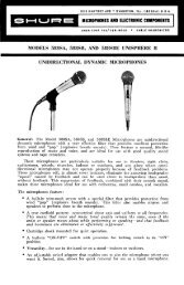
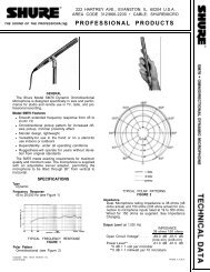
OutputsOutputMicrophoneIMPEDANCEDesigned forUse WithAny low impedancemicrophoneinputActual(Internal)OutputClipping Level0.5 –34 dB(20 mV)Mix Bus 3.5 kΩ 3.5 kΩ –8 dBV(400 mV)Headphones8 - 2000 Ω200 Ωrecommended400 Ω to3 kΩ∗∗+10 dBV(3.3 V)Line 600Ω 150Ω +18 dBm(6.2 V)∗∗Depending on level control settingNoiseEquivalent Input Hum and Noise: –126 dBV (low impedancemicrophone, 150 Ω - 20-20,000 Hz) into a600 Ω load at full gainOutput Noise: –75 dBV (master control fully counterclockwise),–53 dBV (master fully clockwise), (input controlsdown, 300-20,000 Hz)Output Hum and Noise: –70 dBV (master controldown), –51 dBV (master control up) (input controlsdown, 20-20,000 Hz)Distortion0.35% or less THD from 30 to 20,000 Hz at +15 dBmoutput; 0.5% or less IM distortion up to +15 dBm outputlevelCommon Mode Rejection65 dB minimum with input of –20 dBV at 100 HzControl InteractionLess than 1 dB with any control combinationOverload and Shorting ProtectionShorting the outputs, even for prolonged periods, willcause no damage; microphone inputs will not be damagedby signals up to 3 voltsLo-Cut FiltersLimiter6 dB/octave rolloff at 150 HzThreshold: +15 dBm (line output level; adjustablefrom –4 to +18 dBm)Attack Time: 3 msec typicalRecovery Time: 500 msec typicalPeak IndicatorLights 6 dB below clipping or at onset of limiter actionHeadphone Output Clipping Level3.16V (+10 dBV) into 200 ΩTone Oscillator1,000 Hz, 1.5% or less THDPhantom Power30 Vdc open-circuit, 3.3 kΩ series resistance, inputswitches in MIC position onlyOperating VoltageAc Operation: 120 or 240 volts ±10%, 50/60 Hz,9.5W, internally switchableDc Operation: 27 volts nominal at 15 mA typical nosignal,18 mA typical at 0 VU (+4 dBm) output withheadphone load; 21.5 volts minimumBattery life: approximately 20 hours with alkaline batteriesat +4 dBm output in continuous use; three 9-voltbatteries, type NEDA 1604A (Duracell MN1604 recommended)Supplied wired for 120 Vac operation (See Service section for 240Vac operation)Temperature RangeOperating: –18 o to 57 o C (0 o to 135 o F)Storage: –29 o to 71 o C (–20 o to 160 o F)DimensionsWeightSee Figure 1Net:309 mm(12 5 / 32 in.)FIGURE 12.3 kg (5 lb 2 oz)Packaged: 3.2 kg (7 lb 2 oz)Certifications68.8mm(2 23 / 32 in.)6.3 mm( 1 / 4 in. )229 mm(9 in.)Listed by Underwriters’ Laboratories, Inc., and listed byCanadian Standards Association as Certified2
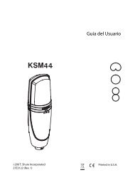
CONTROLS AND CONNECTORSWARNINGThis apparatus must be earthed (grounded)! The<strong>M267</strong> power supply is energized when the unit isconnected to an ac source; disconnect mains(power) plug from supply when not in use.InputsThe four inputs are professional three-pin female XLRaudio connectors located on the rear panel and designatedINPUT 1 through INPUT 4. The inputs are balanced (internaltransformer, MUMETAL shielded); pins 2 and 3 are“hot”, and pin 1 is “ground”. For microphone operation, theswitches labeled LINE/MIC (directly above the input connectors)must be in the MIC position; for line level inputs,the switches must be in the LINE position. For impedance,clipping and operating signal levels, refer to the SPECIFI-CATIONS section.OutputsThe rear-panel connector labeled OUTPUT is a professionalthree-pin male XLR audio connector. With the adjacentLINE/MIC switch in the MIC position, the OUTPUTconnector is used to feed a low-impedance microphoneline or a low-impedance microphone input. With the LINE/MIC switch in the LINE position, the OUTPUT connectorfeeds the line-level input of an amplifier, tape recorder, oranother mixer. The OUTPUT connector is a balanced outputwith the LINE/MIC switch in either position; pin 1 isground, pins 2 and 3 are “hot”, and the connector is inphase with the corresponding pins of the input connectors.The rear-panel binding-post connector designated LINEOUTPUT is in parallel with the OUTPUT connector andcan be used as a line-level output feed simultaneously withthe OUTPUT connector. The terminals are numbered 2and 3 and are in phase with the corresponding pins of theinput connectors. While the line outputs can be used todrive various impedance lines, the VU meter is calibratedfor use with a 600 Ω line.The line output transformer will operate properly with upto 100 mA dc in the line. This feature permits the use ofstandard “dialed-up” telephone lines with dc across them.(Since a slight distortion increase may occur at high outputlevels with maximum dc current, operation with the VURANGE switch at +4 dBm is recommended.)Input Gain ControlsThe front-panel controls designated 1 through 4 are the individualactive gain controls for correspondingly numberedinputs. Note that the input connectors are located on the rearpanel directly behind their corresponding gain control. Thecontrols set the preamplifier gain and provide preamplifieroutput attenuation. As the gain is reduced, the preamplifierinput clipping level is increased for that channel.Input control 1 serves an additional function as the levelcontrol for the tone oscillator when the INPUT 1/OCS 1switch is in the OSC 1 position.IMPORTANT: For optimum signal-to-noise ratio, the individualinput controls should be operated at as high a settingas possible, consistent with maintaining adequatecontrol range and input clipping level.Master Gain ControlThe front-panel control designated MASTER is the mastergain control which sets the overall output level of themixed sources (including signals applied to the MIX BUSinput).LimiterThe front-panel LIMITER IN/OUT switch turns on a fastacting,peak-responding limiter circuit that cuts overloaddistortion during loud program intervals without affectingnormal program levels. When the LIMITER switch is IN(operating), the mixer output is limited to approximately+15dBm. Increasing the individual or MASTER gain controlswill increase the average output and the amount oflimiting. The limiter threshold can be reset to any other outputbetween –4 and +18 dBm if desired. With the limiterswitched OUT and tone oscillator activated, adjust INPUT1 and MASTER level controls to produce an output 0.5 dBhigher than desired. Switch the limiter IN and set the LIM-ITER THRESHOLD ADJUST control (accessible thoughthe bottom of the chassis) for the desired level.The front-panel PEAK LED indicator shows limiter operationwith the limiter in, and operates when program levelsapproach overload with the limiter out. The indicator ismuch faster than a meter and will be activated by the shortesttransient peak, but it remains on long enough to provideeasy recognition.Low-Cut FiltersThe low-cut filters provide a low-frequency rolloff to theresponse curve as shown in Figure 2. The filters are activatedby the LO-CUT IN/OUT switch above each individualinput gain control and can be used individually with eachcontrol to reduce wind noise or undesirable low-frequencysignals such as from condenser microphones or turntablerumble.0–10–202050 100 200LOW-CUT FILTER ACTIONFIGURE 2500 1,0003