Shure M267 User Guide English
Shure M267 User Guide English
Shure M267 User Guide English

Create successful ePaper yourself
Turn your PDF publications into a flip-book with our unique Google optimized e-Paper software.
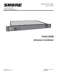
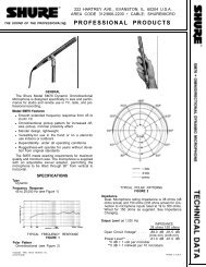
<strong>Shure</strong> Brothers Incorporated222 Hartrey AvenueEvanston IL 60202-3696 U.S.A.Model <strong>M267</strong> <strong>User</strong> <strong>Guide</strong>GENERALThe <strong>Shure</strong> Model <strong>M267</strong> is a microphone mixer-remoteamplifier specifically designed for professional applications.The excellent performance, versatility and features of thiscomplete, compact console make it an ideal choice for studio,remote, or sound reinforcement use, and as an add-onmixer for expanding existing facilities. It is also ideally suitedfor use with audio and video tape recorders to provide multiplemicrophone inputs.Features: Wide, flat frequency response and extremely low distortionup to +18 dBm output Extremely low noise and RF susceptibility Four switchable microphone- or line-level balanced-lineinputs with individual gain controls and low-frequencyrolloff switches. MUMETAL shielding on input transformers Feedback-type input gain controls for maximum clippinglevels and dynamic range Output switchable for line or microphone level Built-in switchable peak limiter cuts output overloaddistortion, adapts to power supply voltage LED indicator shows limiter operation or overload withlimiter defeated Externally adjustable limiter threshold (–4 to +18 dBm) VU meter calibrated for +4 and +8 dBm with rangeswitch. Illuminated with ac operation Ac or built-in battery operation. Noiseless automaticswitchover to battery in case of ac line failure. Batterytest without program interruption Front-panel headphone level control and monitor jackdrives almost any stereo or mono headphones; outputcan be additional unbalanced line feed to drive a taperecorder or power amplifierDirect mix bus for stacking unitsAutomatic muting prevents speaker damage duringturn-on and -offLow distortion, high-stability tone oscillator for line testand level checksAll connections phased. Line output terminals phaseindicatedCompact and lightweight, with rugged, abrasion-resistantcaseInternally selectable 120 or 240 Vac, 50/60 Hz operationUnderwriters’ Laboratories Listed and Canadian StandardsAssociation listed as CertifiedSPECIFICATIONSFrequency Response30 Hz to 20,000 Hz, ±2 dBVoltage Gain (at 1,000 Hz)(Outputs terminated: line 600 microphone 150 mixbus 3.3 k headphone 200 , tip-sleeve and ringsleeve)InputLow-ImpedanceMicrophone (150 Ω)OUTPUTLine Microphone MixBus91 dB 41 dB 24 dBLine 40 dB –9 dB –27 dBMix Bus 55 dB 5 dB – –InputsInputIMPEDANCEDesignedfor UseWithMicrophone 19 to600 ΩLineLessthan10 kΩActual(Internal)1kΩInputClipping Level–32 dBV to–5 dBV∗(25 mV to 0.56 V)66 kΩ +20 dBVMix Bus 3.5 kΩ 3.5 kΩ +7 dBV (2.2 V)∗Depending on input control setting1999, <strong>Shure</strong> Brothers Incorporated27A8376 (SE)Printed in U.S.A.
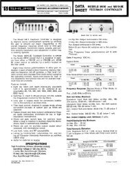
OutputsOutputMicrophoneIMPEDANCEDesigned forUse WithAny low impedancemicrophoneinputActual(Internal)OutputClipping Level0.5 –34 dB(20 mV)Mix Bus 3.5 kΩ 3.5 kΩ –8 dBV(400 mV)Headphones8 - 2000 Ω200 Ωrecommended400 Ω to3 kΩ∗∗+10 dBV(3.3 V)Line 600Ω 150Ω +18 dBm(6.2 V)∗∗Depending on level control settingNoiseEquivalent Input Hum and Noise: –126 dBV (low impedancemicrophone, 150 Ω - 20-20,000 Hz) into a600 Ω load at full gainOutput Noise: –75 dBV (master control fully counterclockwise),–53 dBV (master fully clockwise), (input controlsdown, 300-20,000 Hz)Output Hum and Noise: –70 dBV (master controldown), –51 dBV (master control up) (input controlsdown, 20-20,000 Hz)Distortion0.35% or less THD from 30 to 20,000 Hz at +15 dBmoutput; 0.5% or less IM distortion up to +15 dBm outputlevelCommon Mode Rejection65 dB minimum with input of –20 dBV at 100 HzControl InteractionLess than 1 dB with any control combinationOverload and Shorting ProtectionShorting the outputs, even for prolonged periods, willcause no damage; microphone inputs will not be damagedby signals up to 3 voltsLo-Cut FiltersLimiter6 dB/octave rolloff at 150 HzThreshold: +15 dBm (line output level; adjustablefrom –4 to +18 dBm)Attack Time: 3 msec typicalRecovery Time: 500 msec typicalPeak IndicatorLights 6 dB below clipping or at onset of limiter actionHeadphone Output Clipping Level3.16V (+10 dBV) into 200 ΩTone Oscillator1,000 Hz, 1.5% or less THDPhantom Power30 Vdc open-circuit, 3.3 kΩ series resistance, inputswitches in MIC position onlyOperating VoltageAc Operation: 120 or 240 volts ±10%, 50/60 Hz,9.5W, internally switchableDc Operation: 27 volts nominal at 15 mA typical nosignal,18 mA typical at 0 VU (+4 dBm) output withheadphone load; 21.5 volts minimumBattery life: approximately 20 hours with alkaline batteriesat +4 dBm output in continuous use; three 9-voltbatteries, type NEDA 1604A (Duracell MN1604 recommended)Supplied wired for 120 Vac operation (See Service section for 240Vac operation)Temperature RangeOperating: –18 o to 57 o C (0 o to 135 o F)Storage: –29 o to 71 o C (–20 o to 160 o F)DimensionsWeightSee Figure 1Net:309 mm(12 5 / 32 in.)FIGURE 12.3 kg (5 lb 2 oz)Packaged: 3.2 kg (7 lb 2 oz)Certifications68.8mm(2 23 / 32 in.)6.3 mm( 1 / 4 in. )229 mm(9 in.)Listed by Underwriters’ Laboratories, Inc., and listed byCanadian Standards Association as Certified2
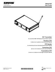
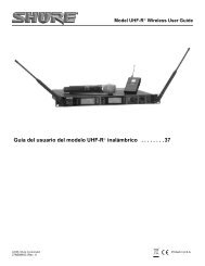
CONTROLS AND CONNECTORSWARNINGThis apparatus must be earthed (grounded)! The<strong>M267</strong> power supply is energized when the unit isconnected to an ac source; disconnect mains(power) plug from supply when not in use.InputsThe four inputs are professional three-pin female XLRaudio connectors located on the rear panel and designatedINPUT 1 through INPUT 4. The inputs are balanced (internaltransformer, MUMETAL shielded); pins 2 and 3 are“hot”, and pin 1 is “ground”. For microphone operation, theswitches labeled LINE/MIC (directly above the input connectors)must be in the MIC position; for line level inputs,the switches must be in the LINE position. For impedance,clipping and operating signal levels, refer to the SPECIFI-CATIONS section.OutputsThe rear-panel connector labeled OUTPUT is a professionalthree-pin male XLR audio connector. With the adjacentLINE/MIC switch in the MIC position, the OUTPUTconnector is used to feed a low-impedance microphoneline or a low-impedance microphone input. With the LINE/MIC switch in the LINE position, the OUTPUT connectorfeeds the line-level input of an amplifier, tape recorder, oranother mixer. The OUTPUT connector is a balanced outputwith the LINE/MIC switch in either position; pin 1 isground, pins 2 and 3 are “hot”, and the connector is inphase with the corresponding pins of the input connectors.The rear-panel binding-post connector designated LINEOUTPUT is in parallel with the OUTPUT connector andcan be used as a line-level output feed simultaneously withthe OUTPUT connector. The terminals are numbered 2and 3 and are in phase with the corresponding pins of theinput connectors. While the line outputs can be used todrive various impedance lines, the VU meter is calibratedfor use with a 600 Ω line.The line output transformer will operate properly with upto 100 mA dc in the line. This feature permits the use ofstandard “dialed-up” telephone lines with dc across them.(Since a slight distortion increase may occur at high outputlevels with maximum dc current, operation with the VURANGE switch at +4 dBm is recommended.)Input Gain ControlsThe front-panel controls designated 1 through 4 are the individualactive gain controls for correspondingly numberedinputs. Note that the input connectors are located on the rearpanel directly behind their corresponding gain control. Thecontrols set the preamplifier gain and provide preamplifieroutput attenuation. As the gain is reduced, the preamplifierinput clipping level is increased for that channel.Input control 1 serves an additional function as the levelcontrol for the tone oscillator when the INPUT 1/OCS 1switch is in the OSC 1 position.IMPORTANT: For optimum signal-to-noise ratio, the individualinput controls should be operated at as high a settingas possible, consistent with maintaining adequatecontrol range and input clipping level.Master Gain ControlThe front-panel control designated MASTER is the mastergain control which sets the overall output level of themixed sources (including signals applied to the MIX BUSinput).LimiterThe front-panel LIMITER IN/OUT switch turns on a fastacting,peak-responding limiter circuit that cuts overloaddistortion during loud program intervals without affectingnormal program levels. When the LIMITER switch is IN(operating), the mixer output is limited to approximately+15dBm. Increasing the individual or MASTER gain controlswill increase the average output and the amount oflimiting. The limiter threshold can be reset to any other outputbetween –4 and +18 dBm if desired. With the limiterswitched OUT and tone oscillator activated, adjust INPUT1 and MASTER level controls to produce an output 0.5 dBhigher than desired. Switch the limiter IN and set the LIM-ITER THRESHOLD ADJUST control (accessible thoughthe bottom of the chassis) for the desired level.The front-panel PEAK LED indicator shows limiter operationwith the limiter in, and operates when program levelsapproach overload with the limiter out. The indicator ismuch faster than a meter and will be activated by the shortesttransient peak, but it remains on long enough to provideeasy recognition.Low-Cut FiltersThe low-cut filters provide a low-frequency rolloff to theresponse curve as shown in Figure 2. The filters are activatedby the LO-CUT IN/OUT switch above each individualinput gain control and can be used individually with eachcontrol to reduce wind noise or undesirable low-frequencysignals such as from condenser microphones or turntablerumble.0–10–202050 100 200LOW-CUT FILTER ACTIONFIGURE 2500 1,0003
Mix BusDirect access to the mixing bus is provided through therear-panel MIX BUS phono pin jack. This provision is madeprimarily to facilitate stacking or “multing” <strong>M267</strong>s toachieve additional input capacity without losing any inputs.With two <strong>M267</strong>s, for example, the two mixing buses are directlyconnected, providing two independent master gaincontrols and two isolated line amplifiers with eight individuallycontrolled inputs. Since the buses are directly paralleled,a 6 dB drop in gain will occur; and the master or inputcontrols must be increased to compensate. Noise specificationsare not adversely affected by this interconnection.Mix bus interconnection can also be made with other<strong>Shure</strong> mixers, such as the M268, FP42. etc.VU MeterThe VU meter is factory-calibrated for use with a 600 Ωterminated line. The VU RANGE switch on the rear panelselects either a +4 or +8 dBm output at 0 VU meter indication.(This switch changes the meter indication but doesnot change the actual output level.) Microphone outputlevels are 50 dB below line output. The +4 range is recommendedfor normal use to provide approximately 14 dB ofheadroom from operating level to clipping level.The VU meter is illuminated by two No. 86 lamps operatingwell under their normal ratings for a life expectancy ofgreater than 10,000 hours. The lamps are only lit duringac operation. Consequently, the illumination serves as avisual alarm if the ac is interrupted and the unit hasswitched to battery.The VU meter is connected on the primary side of theoutput transformer to assure protection from any dc levelon a telephone line.HeadphonesThe headphone outlet appears at the front-panel jackpanel designated PHONES. The two-circuit phone jackwill accommodate most stereo or mono headphones. Theoutput level is sufficient to provide high volume for use innoisy environments.Note that the headphone output level is also highenough to use as an auxiliary unbalanced line feed to drivea tape deck or a power amplifier.The tip and ring connections of the headphone plugs arein phase with pin 3 of all input and output connectors, andwith the tip of the MIX BUS jack.Tone OscillatorThe highly stable, low-distortion tone oscillator providesfor line test and level checks. The oscillator is instantly activatedby the front-panel INPUT 1/OSC 1 switch; its levelcan then be controlled by the INPUT 1 gain control on thefront panel. The tone oscillator frequency is 1,000 Hz, andthe signal appears on both the line and microphone outputs,as well as the headphone and mix bus connectors.The oscillator should be switched off (INPUT 1 position)when not in use.Phantom PowerThe rear-panel PHANTOM OFF/ON switch controls theapplication of phantom power for condenser microphones,such as the <strong>Shure</strong> SM81 and SM87A, to all inputs. Withthe switch on and the rear-panel MIC/LINE switches in theMIC positions, +30 Vdc is applied to pins 2 and 3 of eachinput connection. Series current-limiting resistance is 3.3kΩ for each input. When using other condenser microphoneswith the <strong>M267</strong>, verify that the voltage and resistancerequirements are compatible.Note that the phantom power cannot normally be appliedto the inputs with the MIC/LINE switches in the LINEposition.IMPORTANT: Do not turn the PHANTOM switch on whenusing unbalanced low-impedance microphones; objectionablehum will result. Turn off the PHANTOM switchwhen condenser microphones are not being used.Use only high-quality cable. Intermittent shorts betweenbroken shield wires and balanced conductors will cause offensivenoise transients in the system.BATTERY OPERATION AND EXTERNAL POWERINGIn addition to ac operation, the <strong>M267</strong> can be operatedfrom an internal battery pack. Current drain is typically 17mA at +8 dBm output level and typically 15 mA at + 4 dBm.Battery power is recommended both for remote, on-locationoperation, and as an emergency backup source incase of failure of the ac power.Access to the battery compartment is provided at thebottom of the chassis. Three 9-volt alkaline batteries powerthe <strong>M267</strong> at full rated output. Use alkaline batteries formaximum life. Duracell MN1604A or Eveready 522 arerecommended. Battery life is approximately 20 hours at +4dBm continuos use. Note that battery operation with phantompower loads and high level headphone monitoring willincrease battery drain.With batteries in the battery compartment, the <strong>M267</strong> willautomatically and silently switch to battery operationshould the ac voltage fall below a suitable level. If the acpower fails completely, the VU meter lamps will go out, providinga visual indication of line failure.Battery condition can be determined by using the BATTCHECK switch on the front panel. Activate the BATTCHECK switch and observe the VU meter. A new set ofbatteries will give about a +2 VU indication. Battery conditionis good if the reading is above 0 VU; a lower readingmeans that new batteries are required for proper operation.Note that the <strong>M267</strong> power switch must be turned onto check battery condition.Telephone InterconnectionWhen using the <strong>M267</strong> connected directly to a telephoneline, check to see whether the local telephone company requiresan interface coupler between the <strong>M267</strong> and the telephoneline. If a coupler is required, make certain the couplerselected and the wiring arrangement are incompliance with the telephone company regulations.4
Telephone Line Surge ProtectionWhen using the <strong>M267</strong> connected directly to a telephoneline subject to lightning-induced voltage surges, the followingcommercially available part can be installed across theLINE OUT terminals to provide additional protection foroutput circuit components:Metal Oxide Varistor, General Electric Co., Type No.V22ZA1ACCESSORIESA268R Rack Panel Kit. The Model A268R Rack Panel Kitincludes a 19 in. x 3- 1 / 2 in. (483 mm x 89 mm) precut rackpanel and necessary hardware for rack-mounting the<strong>M267</strong> (with its cover in place and end caps removed) in astandard 19 in. (483 mm) rack panel.RKC169 Rack Panel Bracket Kit. The Model RKC169Rack Panel Bracket Kit enables owners of the <strong>Shure</strong> A68RRack Panel Kit (originally designed for the M67 and M68Mixers) to rack-mount the <strong>M267</strong> with the A68R.SERVICEWARNINGVoltages in this equpment are harzardous!Refer servicing to qualified service personnel.240 Vac OperationTo change the <strong>M267</strong> operating voltage from 120 Vac to240 Vac, follow these steps:1. Disconnect the <strong>M267</strong> from the ac line.2. Remove the end caps and cover.3. Locate the voltage selector switch (S201) at the rightrear of the main printed circuit board (Figure 3). MoveSD201 to the 240V position (toward the front panel).BLKF202T50/250VF201WHT120V240VS201T206240 V WIRINGFIGURE 34. Remove fuse F201 (0.1A, 250V, time lag) and replaceit with the supplied fuse F202 (0.05A, 250V, time lag).Note that the F202 fuse holder is at right angles to theF201 fuse holder.5. Replace the ac line cord (if necessary) with one designedfor the 240 Vac source. If the <strong>M267</strong> is to beused outside the U.S. and Canada, local regulationsmay require replacing the line cord with one havingwire insulation colors as follows:“Live” or“Hot” NeutralEarth orGroundU.S., Canada Black White GreenEurope Brown Blue Green/Yellow6. Replace the cover and end caps, and mark the rearpanel to reflect the new operating voltage.5
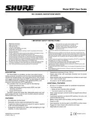
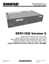
PRINTED CIRUCIT BOARDSCOMPONENT SIDEINPUT TRANSFORMERS T201-T2046
REPLACEMENT PARTS LISTREFERENCEDESIGNATIONC101,C209,C219, C227,C232PARTCOMMERCIALNUMBER DESCRIPTIONALTERNATE86T628 Capacitor, Electrolytic, 5 µF, 25V Sprague TVA 1303C115 86L628 Capacitor, Electrolytic, 250 µF, 50V Sprague501D227F063PRC201, C204-C205, C20886V628 Capacitor, Electrolytic, 22 µF, 6.3V Sprague501D226F016LLC210 86M630 Capacitor, Electrolytic, 10 µF, 25V Sprague TE 1204C212-C213 86R630 Capacitor, Electrolytic, 68 µF, 25V Sprague501D686F025MNC215, C218 86L626 Capacitor, Electrolytic, 470 µF, 35V Sprague503D477F035QEC216, C222 86A630 Capacitor, Electrolytic, 5 µF, 35V Sprague TE1303C221, C229 86N630 Capacitor, Electrolytic, 22 µF, 35V Mallory F226KMC223 86S628 Capacitor, Electrolytic, 1 µF, 50V Sprague TVA1300D209,86A415 Diode, Silicon, Computer, 75V TI 1N4148D211-D214,D222-D223,D226-D229D210, D217, 86A404 Silicon Rectifier, 100V, 1/2A Motorola 1N4002D230-D235D218-D221 86A405 Diode, Germanium, 30V RCA 1N48, 1N60D301 86F422 Diode, Light-Emitting General InstrumentMV5075CF201 80F159 Fuse, Slow–Blow, 3AG, 0.1A, 250V Littlefuse 313000 SeriesF202 80C380 Fuse, Time Lag, 0.05A, 250V Schurter 034.3104J1 95C450 Jack, Phono Switchcraft 3511AJ2A, B 90T2600 Connectors, Binding Post NoneJ101-J104 95B8011 Connector, 3-Pin Female XLR Switchcraft Y3FDPCJ105 95B8012 Connector, 3-Pin Male XLR Switchcraft Y3MPCJ301 90BJ2600 Phone Jack Switchcraft L-1128PCL101-L113 80A365 Ferrite Bead Ring PanasonicExc-ELSA35M1RKC170(95A8214)Meter, 190 µANoneMP1-MP5 90A8028 Knob, MIC 1-4, MASTER NoneMP6 90A8029 Knobs, PHONE NoneMP7 90A8027 Cover, Battery NoneMP8-MP9 65A8008 End Cap NoneREFERENCEDESIGNATIONPARTNUMBERDESCRIPTIONCOMMERCIALALTERNATEPL301-PL302 95A8010 Lamp, 6.3V, 0.2A Sylvania 86Q201 86A350 Transistor, NPN Motorola 2N5210Q202, Q204 86A334 Transistor, NPN Rohm TIS92Q203, Q205 86A348 Transistor, PNP Motorola 2N5087Q206 86A335 Transistor, PNP Rohm TIS93Q207 86A8302 Transistor, PNP Motorola TIP30AR250 46A8016 Potentiometer, 100k NoneR302, R306,R310, R31446B8000 Potentiometer, 100k NoneR317 46C8000 Potentiometer, 200k NoneR322 46D8000 Potentiometer, 5k NoneS101-S104 55B8008 Switch, Slide, 3PDT NoneS105, S302, S306 55B8007 Switch, Slide, DPDT NoneS106-S107, S301,S303-S30555B8001 Switch, Slide, DPDT NoneS201 55A8035 Switch, Slide, DPDT Switchcraft EPS1-PC1S307 90CB2600 Switch, Pushbutton, SPDT Switchcraft 953S308 55A8009 Switch, Slide, 3PDT NoneT201-T204 95B8165 Transformer, Input NoneT205 51E235A Transformer, Output NoneT206 51A8021 Transformer, Power NoneU201 86B808A Integrated Circuit, Quad Op Ampl(Selected for NF)U202 86A8908 Opto-Isolator NoneRaytheon RC4156NU203 86A811A Integrated Circuit, Dual Op Ampl Raytheon RC4559NBU204 86A806A Integrated Circuit, Quad Comparator Raytheon LM339DBU205 86A811A Integrated Circuit, Dual Op Ampl Raytheon RC4559NBU206 86A803 Integrated Circuit, Dual Op Ampl Motorola MC1458C-P1U207 86B8930 Integrated Circuit, Voltage Regulator National SemiconductorLM317ATW1 90A8045 Line Cord, AC NoneParts listed as RKC Kits should be ordered by that kit number.9