Light oil - kerosene burners - Riello Burners
Light oil - kerosene burners - Riello Burners
Light oil - kerosene burners - Riello Burners

Create successful ePaper yourself
Turn your PDF publications into a flip-book with our unique Google optimized e-Paper software.
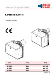
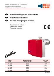
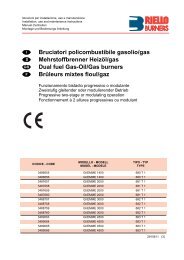
Installation, use and maintenance instructions<strong>Light</strong> <strong>oil</strong> - <strong>kerosene</strong> <strong>burners</strong>One stage operationCODE MODEL TYPE3743751 G3B 437T503743753 G3B 437T503743754 G3B 437T502902380 (5)
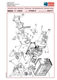
TECHNICAL DATAThermal power – output 19 – 35 kW – 1.6 – 3 kg/hFuel<strong>Light</strong> <strong>oil</strong> 35 sec max. viscosity 6 mm2/s at 20 °CKerosene 28 secElectrical supply Single phase, 230V ± 10% ~ 50HzMotorRun current 0.85A – 2850 rpm – 298 rad/sCapacitor 4 µFIgnition transformerPumpAbsorbed electrical powerSecondary 8 kV – 16 mAMaximum pressure 14 bar (203 psi)0.115 kW■ Burner with CE marking in conformity with EEC directives: EMC89/336/EEC, Low Voltage 73/23/EEC,Machines 89/392/EEC and Efficiency 92/42/EEC.■ The burner meets protection level of IP 40, EN 60529.Fig. 17864693D55062151 – Return line2 – Suction line3 – Gauge connection4 – Pump pressure regulator5 – Vacuum gauge connection6 – Screws fixing air-damper7 – Hydraulic jack with air-damper8 – Lock-out lamp and reset button9 – Flange with insulating gasketBURNER EQUIPMENTQuantity112111DescriptionFlexible pipe with nippleFlange with insulating gasketScrews and nuts for flangeScrew of pump by-passCable glandScrew with two nuts for flange23801
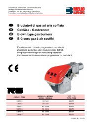
FIRING RATE (as EN 267)Pressure in the combustionchamber – mbar0.80.60.40.201.5 2 2.5 3 Fuel output - kg/hD522320 25 30 35 Thermal power - kWOVERALL DIMENSIONSFlange180=Burner252 93 203=45°45°1175 72215164ø 9013015019D5509MOUNTING THE BURNERIt is necessary that the insulating gasket(9, fig. 1) is placed between the b<strong>oil</strong>er doorand the burner flange.This insulating gasket has six holes,which, if necessary, can be modified asshown on the drawing on the right.Verify that the installedburner is lightly leanedtowards the button.(See figure 2).D5242Fig. 2BURNER FIXINGThe burner is designed toallow entry of the flexible<strong>oil</strong>-lines on either side ofthe burner.S7386D521823802
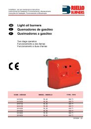
OIL LINESD5219min. 0.1 mHmax. 4 mPRIMING THE PUMPLoosen the plug of the vacuumgauge (5, fig. 1) and wait until thefuel flows out.Hmeters0.511.52L metersI. D.8 mm10204060I.D.10 mm204080100H = Difference of level.L =Max. length of thesuction line.I.D.= Internal diameter of the<strong>oil</strong> pipes.HD5220H max. 4 mHmeters00.511.5233.5L metersI. D.8 mm353025201586I.D.10 mm10010010090703020WARNINGThe pump is supplied for use witha one pipe system. For use on a two pipe system, itis necessary to screw the by-pass screw (A) suppliedas burner’s accessory. (See figure).The pump vacuum should not exceed a maximum of 0.4 bar (30 cm Hg).Beyond this limit gas is released from the <strong>oil</strong>.Oil lines must be completely airtight.The return line should terminate in the <strong>oil</strong> tank at the same levelas the suction line; in this case a non-return valve is not required.Should however the return line arrives over the fuel level, the nonreturnvalve is indispensable.This solution however is less safe than previous one, due to the possibilityof leakage of the valve.AD5199PRIMING THE PUMP:Start the burner and wait for the priming. Should lock-out occur prior to the arrival of the fuel, await atleast 20 seconds before repeating the operation.Warning: before starting the burner make sure that the return pipe-line is not clogged: any obstructionwould cause the pump seals to break.WARNING:■ Check periodically the flexible pipes conditions. Using <strong>kerosene</strong>, they have to be replaced atleast every 2 years.■ A metal bowl filter with replaceable micronic filter must be fitted in the <strong>oil</strong> supply pipe.23803
ELECTRICAL WIRING230V ~ 50HzN LWARNINGDo not exchange the neutral with the phase.Switch with fuse6A max.NeutralTRegulating thermostatTLimit thermostatwith manual resettingNLRemote lock-out lamp(230V - 0.5A max.), if requiredCARRIED-OUT IN THE FACTORYValve1 2 3 4 5 6 7 8 9BlueBlueWhite (50V)BrownBrownBlackBlackCapacitorM~MotorTerminal block ofcontrol-box 530SE*D5228NOTES– Wires of 1 mm 2 section.– The electrical wiring carried out by the installermust be in compliance with the rules in force inthe Country.– To remove the control-box from the burner,loosen screw (A) (see figure) and pulltowards the arrow.– The photoresistance is fitted directly into thecontrol-box (underneath the ignition-transformer)on a plug-in support.A 3 2 1S7026TESTINGCheck the shut-down of the burner by opening thethermostats.RUN OF THE ELECTRICAL CABLE1 - Cable gland N - Neutral2 - Cable-clamp L - Phase3 - Terminal block - Burner-earth23804
COMBUSTION ADJUSTMENTIn conformity with Efficiency Directive 92/42/EEC the application of the burner on the b<strong>oil</strong>er, adjustmentand testing must be carried out observing the instruction manual of the b<strong>oil</strong>er, including verification ofthe CO and CO 2 concentration in the flue gases, their temperatures and the average temperature ofthe water in the b<strong>oil</strong>er.To suit the required appliance output, fit the nozzle then adjust the pump pressure and the air damperopening in accordance with the following schedule.NozzleLIGHT OIL FUELPumppressureBurneroutputAir damperadjustment1 2 3GPH Angle bar kg/h ± 4% Set-point0.40 80°/60° 12 1.72 1.950.50 60° 12 2.15 2.20.60 60° 12 2.58 2.80.65 60° 12 2.79 3.20.65 60° 13 2.91 3.7NozzleKEROSENE FUELPumppressureBurneroutputAir damperadjustment1 2 3GPH Angle bar kg/h ± 4% Set-point0.50 60° 8 1.5 1.50.60 60° 8 1.8 1.750.65 60° 8 1.9 2.10.75 60° 8 2.2 2.50.85 60° 8 2.5 3.01.00 60° 8 3.0 4.01 NOZZLES RECOMMENDED:Monarch type R - NSDelavan type W - A - ESteinen type H - QDanfoss type H - B1 NOZZLES RECOMMENDED:Monarch type R - NSDelavan type W - A - ESteinen type H - QDanfoss type H - BAngle:60° - in most cases.80° - in cases of flame detachment,during ignitions at low temperatures.2 PRESSURE:8 bar: the pump leaves the factory set at thisvalue, which is suitable only for <strong>kerosene</strong>.2 PRESSURE:8 bar: the pump leaves the factory set at thisvalue.10 bar: maximum pressure for <strong>kerosene</strong>.FOR LIGHT OIL INCREASE PRESSURE12 bar: pressure suitable for light <strong>oil</strong> in mostcases.14 bar: improves flame retention; it is thereforesuitable for ignitions at low temperatures.23805
3 AIR DAMPER ADJUSTMENT: The mobile air damper (1) operated by the jack (2) assuresthe complete opening of the air intake.1 2 The regulation of the air-rate is made by adjusting the fixedair damper (3), after loosing the screws (4). When theoptimal regulation is reached, screw tight the screws (4)to assure a free movement of the mobile air damper (1).4D555034The settings indicated in the schedule refer to the burnerwith its metal cover fitted and the combustion chamber with“zero” depression.These regulations are purely indicative.Each installation however, has its own unpredictableworking conditions: actual nozzle output; positive ornegative pressure in the combustion-chamber, the need ofexcess air, etc. All these conditions may require a differentair damper setting.It is important to take account of the fact that the air output of the fan differs according towhether the burner has its metal cover fitted or not.Therefore we recommended to proceed as follows:– adjust the air damper as indicated in the schedule (3);– mount the cover, simply by means of the upper screw;– check smoke number;– should it become necessary to modify the air output, remove the cover by loosening the screw,adjust the air damper, remount the cover and finally recheck the smoke number.ELECTRODE SETTINGAttention:Before assembling or removingthe nozzle, loosen the screw (A)and move the electrodes ahead4 ± 0.3 mmIMPORTANT:THESE DIMENSIONSMUST BE OBSERVEDD5230A2 – 2.5 mmBURNER START-UP CYCLEThermostatMotorIgnition transformerValveFlameLock-out lampNormal~ 12sLock-out, due to light-failure~ 12s ~ 5sD522923806
SAFETY WARNINGSThe dimension of the b<strong>oil</strong>er’s combustion chamber must respond to specific values, in order toguarantee a combustion with the lowest polluting emissions rate.The Technical Service Personnel will be glad to give you all the imformation for a correct matchingof this burner to the b<strong>oil</strong>er.This burner must only be used for the application it was designed for.The manufacturer accepts no liability within or without the contract for any damage caused topeople, animals and property due to installation, adjustment and maintenance errors or toimproper use.BURNER IDENTIFICATIONThe Identification Plate on the product gives the serial number, model and main technical andperformance data.If the Identification Plate is tampered with, removed or missing, the product cannot be clearlyidentified thus making any installation or maintenance work potentially dangerous.BASIC SAFETY RULES➤ Children or inexpert persons must not use the appliance.➤➤➤➤➤➤➤➤Under no circumstances must the intake grids, dissipation grids and ventilation vents in theinstallation room be covered up with cloths, paper or any other material.Unauthorised persons must not attempt to repair the appliance.It is dangerous to pull or twist the electric leads.Cleaning operations must not be performed if the appliance is not disconnected from themain power supply.Do not clean the burner or its parts with inflammable substances (e.g. petrol, alcohol, etc.).The cover must be cleaned with soapy water.Do not place anything on the burner.Do not block or reduce the size of the ventilation vents in the installation room.Do not leave containers and inflammable products in the installation room.23807