Electrical Shorting In Multilayer Ceramic Capacitors - ECA Digital ...
Electrical Shorting In Multilayer Ceramic Capacitors - ECA Digital ...
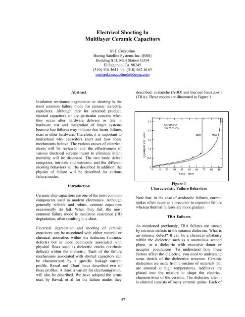
Electrical Shorting In Multilayer Ceramic Capacitors - ECA Digital ...

Create successful ePaper yourself
Turn your PDF publications into a flip-book with our unique Google optimized e-Paper software.
Figure 9 illustrates the temperature verses IRcharacteristic for a capacitor that failed due to thismechanism. This response was higher erratic andexhibited a slightly negative TC that is typical ofneither a dielectric nor the electrode metallization.Capacitor and DF were measured in the recoveredstate and were indicate to behave normally over bothfrequency and temperature.capacitor was verified to have approximately a onemegohm short. <strong>In</strong>sulation resistance was measuredboth under forward and reverse bias as a function ofvoltage (Figure 10) and found to be slightly offset.1.6<strong>In</strong>itial value<strong>In</strong>sulation Resistance verses Voltage1.4IR verses Temperature1.230025020015010 050010 10 0 10 0 0Temperature (C)IR (megohm)10.80.60.40.200 5 10 15 20 25 30VoltageForward ReverseFigure 9IR Characteristic for a Low Voltage FailureThis mechanism was hypothesized to be due tovarious causes such as ionic contamination withinthe dielectric, second phases, etc. However, directisolation of the failure site(s) was not successful.Chittick and Alexander 6 solved this conundrum bydemonstrating through the effect of moisture onanomalous capacitors that this mechanism was theresult of electromigration of the electrode materialsalong cracks within the dielectric. (Electromigrationis a complex phenomena that depends on thehumidity, the metals involved, the nature of thesurface, etc. This mechanism will be discussed inmore detail below.) Therefore, the cause of failurewas dielectric cracking. <strong>Capacitors</strong> would fail andrecover suddenly as dendrites spanned the distancebetween electrodes and then melted open. The factthat capacitor failure would be accelerated bymoisture is well established for electromigration.However, the mechanism for failure under ‘dry’conditions is less well established as will bediscussed below.Example 3 Cracked DielectricThe following example failed during a qualificationlife test in which the current available during failurewas limited to milliamperes due to a high in circuitresistance. <strong>In</strong> this case, there were no visualindications of failure. The capacitor was a X7Rdielectric, high reliability chip capacitor. TheFigure 10V/I CharacteristicsWires were soldered to the capacitorterminations and the capacitor was encapsulatedsuch that it could be cross-sectioned through itsside. Cross-sectioning is a wet process.Therefore, insulation resistance during thesectioning process could not be monitoredbecause of the conductivity of the sectioningmedia and the water that cools the sample. Thecross-sectioning process was frequently haltedand the sample was dried such that ameasurement could be made and the part couldbe visually inspected. It was noted that therewas a large crack under the capacitors'termination (Figure 11).Figure 11Radiograph of Cracked Capacitor61
Cross-sectioning was continued until theinsulation resistance was noted to be increasing.Dark field inspection of the device revealed thatpart of the crack was discolored (Figure 12).The termination was removed from one end ofthe capacitor and the electrodes were exposedand electrically probed. The short was isolatedto the area of the discoloration. Energydispersive analysis of X-rays (EDAX) revealedthat the discolored area of the crack was filledwith electrode material. Failure was caused byelectro-migration of the electrical metallizationalong a crack in the dielectric. (The initialmicrocrack was created during capacitorfabrication at the manufacturer. It extendedduring reflow soldering to the printed wiringboard and during thermal cycling.)<strong>In</strong> many of these examples failure is caused oraccompanied by movement of electrode materialbetween the two electrodes. One cause formovement is heat. That is, a locally overheateddielectric will draw the adjacent metallization into it.This is commonly seen in cases of severe failure.The second cause for metal movement iselectromigration. Electromigration is the movementof a metal across a non-metallic medium under theinfluence of an applied electrical field. Figure 13illustrates a classic example of surface migration andFigure 14 indicates a “melt” zone where someelectrode material has migrated into a failure site.Surface migration of ions, in the above case- silverin the presence of moisture, has been extensivelystudied. However, many of the details of its physicsremain in question. We will present one view of thesubject herein. Electromigration can be divided intotwo classes. Electrolytic and solid state migration.Electrolytic migration requires an electrolyte whilesolid state migration requires heat and current..ElectromigrationFigure 12Metal filled crackFigure 14Failure ‘Melt’ SiteElectrolytic ElectromigrationElectrolytic migration is an electrochemicalphenomenon that can occur under ambient moistureand temperature conditions. (Ambient conditions aredefined as a temperature of less than 100C andcurrent density less than 100 ma/cm 2 .) Thisphenomenon requires 3 stages for completion:Figure 13Surface Electromigrationa) Oxidation or dissolution of a metal at theanode,b) Migration across an insulator, and62
c) Reduction and deposition of the metal ionsat the cathode.Typically electromigration is seen to occur across asurface. However, in the case of a multiplayerceramic capacitor, a path is typically requiredbetween two internal electrodes. This path comes inthe form of a crack or a void. The positively chargedelectrode becomes the source of the migrating metalthat is deposited at the cathode. Since cracks incapacitors are narrow, dendrites tend to be narrowand relatively high resistance. Silver, a commonmaterial in electrode formulations, dissociates andmigrates under ambient humidity. Therefore, all thatis required for migration are several monolayers ofwater. (As an example of how easy dielectricsabsorb water, Figure 15 illustrates a cracked ceramicsurface which was found to undergo electrolysis inan ambient environment when a bias was appliedacross a cracked metallization. There was no watervisible prior to testing.)Wet migration is a bulk phenomenon that occurs at arate that is proportional to the voltage gradient andinversely proportional to the electrode spacing. Itstemperature dependence is given by the temperaturedependence of the ionic mobility of the migratingmetal. <strong>In</strong> the case of humid electromigration in acracked capacitor the physics becomes morecomplex than the wet case. For humid migration, themovement of metal is also governed by the nature ofthe cracked surface, the viscosity and dielectricconstant of the liquid (including any contaminates).Another difference is that wet migration can occurvery rapidly. AMP reported that dendrite formationtook a week to occur at 90RH and 45C for a samplewith 15 millinch spacing and a 10 volt applied bias.The same experiment under ‘wet’ conditionsrequired less than 1 minute for bridging of the gap.Another difference between humid and wetmigration is the range of materials affected. Humidmigration occurs for silver and few other materials.Wet migration affects a wider range of materialsincluding gold, palladium, and nickel.Solid State ElectromigrationFigure 15Electrolysis across a cracked dielectric<strong>In</strong> the case of an internally cracked capacitor, it isbelieved that the required water enters the capacitorthrough the capacitor terminations and travels alongthe electrode plane. Other metals, includingpalladium, require a visible layer of water for wetmigration to occur. (Since electrodes generallyconsist of silver and palladium as well as othermetals, it is thought that internal electromigration issomewhat inhibited in most capacitors by this mix ofmaterials.) Because of the fact that some metalsrequire less moisture than others for migration,Krumbein 8 further classifies migration into twoclasses: ‘wet’ and ‘humid’.Figure 13 depicted a failed capacitor where therewas a metal filled crack without the melted regionsnormally associated with failure. <strong>In</strong> the case of thisfailure, failure occurred after hundreds of hours at125C and twice rated voltage. Therefore, metalobviously migrated but there would have been nomoisture available. <strong>In</strong> this case, failure was causedby solid state migration. (This is also termed dryelectromigration.) Largely associated withmovement of silver through solid electrolytes suchas glass, it is a phenomenon that, as far as commonelectrode materials are concerned, is unique to silver.Silver can grow in the absence of moisture if thetemperature is high (>150C) and the current densityis high (>10 4 amp/cm 2 ). Wet, humid and dryelectromigration all have the same physicalappearance. For dry electromigration to occur in amultilayer capacitor, several conditions are required.First, the silver needs to be oxidized such that it canbe easily dissociated. This will generally occurduring the dielectric sintering process. It also needs apath. A physical flaw such as a crack provides thispath. Next, a high temperature and a high currentdensity are required. This is created during theprocess of thermal runaway along the crack front.The increased temperature increases the mobility ofthe silver and the high current value creates pressureon the silver due to momentum transfer fromelectron collisions..63
This phenomenon is believed to be the cause offailures that occur in dry environments wherefailures may occur after hundreds of hours onaccelerated test. This slow time to failure is afunction of the slow buildup of heat as thermalrunaway develops along a flaw. As the local areaheats silver will begin to move along the electricalgradient from the grain boundaries. As heatincreases to 50% of silvers melting point or 480C,silver will begin to flow from the bulk of the silvergrains. As mentioned this can be a very slowmechanism. Experiments performed under dryconditions revealed no migration after 700 hoursacross 15 mil gaps at 600 volts whereas capacitorswith 1 mil gaps can fail after less than 200 hours at200 volts. <strong>In</strong> either case, this can represent yearsunder normal derated bias and operationaltemperatures.positives. That is, artifacts may be identified forwhich no defect can be later found during crosssectioning. (There are various reasons given for thiseffect including: water bubbles, porous electrodelaydowns, and the presence of terminations andrough capacitor surfaces.) Therefore, this techniqueis at its best when used for high reliabilityapplications when it is acceptable to reject a numberof questionable, possibly defect free parts in order toeliminate the defective samples within the lot. Thistechnique is also best accomplished prior tocapacitor termination since the terminations canmask anomalies. (A delaminated part is illustrated inFigure .)Defect Detection and EliminationVarious capacitor specifications attempt to eliminatecomponent defects by the use of techniques such asenvironmental conditioning, inspection andscreening operations. A listing of these techniquescan be found in Table I. Each of these operations hasstrengths and weaknesses and each will be describedand discussed below. Use of these techniques willdetect and eliminate all but the rare exceptionaldefect. (Several techniques, such as dye penetrateinspection, which are more commonly used forfailure analysis will not be discussed.)Ultrasonic inspection.This technique utilizes focused ultrasound to imageanomalies within a capacitor. <strong>Ceramic</strong> capacitormanufacturers employ both home brewed andcommercial systems to perform inspection. Twogeneral modes are utilized, through transmission andpulse echo. The transmission mode measures howmuch ultrasound penetrates the ceramic. Any defectin the path of the sound will reflect the sound andreduce transmission. The amplitude of the a falsecolor scale on a CRT screen. Pulse echotransmissions are focused through a lens into thebody of the dielectric to a predetermined level. Thistechnique displays the amount of reflected energy asa gray scale or false color image. The resolution ofthe technique and the amount of sample penetrationwill be a function of the frequency utilized.When properly performed ultrasonic screeningexcels at identifying capacitors with cracks anddelaminations. However, it can also generate ‘false’Biased Humidity TestingFigure 16Delaminated CapacitorBiased high humidity testing was increasinglyincorporated into specifications in the early 1980’swhen it was identified as an excellent technique toinspect capacitors for dielectric cracks. <strong>In</strong> thistechnique, moisture penetrates the ceramic to thecrack site and either enhances surface conductionalong the crack surfaces or migration of theelectrode material. (This test is performed at 65%RH or greater and 85C. Since the dielectric itself isnot porous, moisture is believed to enter thecapacitor though the termination and electrodeinterfaces.) This remains an excellent technique toidentify systemic cracking. However, it can only beused as a lot sample test since it is considereddestructive and therefore will not always identifyproblems affecting small subpopulations of a lot.64
Voltage ConditioningVoltage conditioning is the most common techniqueused to eliminate infant mortality from capacitorlots. Voltage conditioning is performed by exposingcapacitors to a minimum of the parts rated voltageand the capacitors’ maximum rated temperature.This process accelerates degradation in defectivecapacitors and enhances lot reliability. (Test circuitimpedance is minimized to assure that enoughcurrent is available to cause catastrophic failure ofdefective parts.) Testing is simple andstraightforward and is universally referenced inmilitary and OEM specifications.While voltage conditioning is recommended as anessential element of screening for all high reliabilityapplications, it does have limitations. For example, itwill not identify anomalous lots, which have highsteady state failure rates. Also, the reliability of thespecific lots following testing is generally notknown. These weaknesses can be minimized in twoways. First, create a failure free period. That is, donot allow more than X failures in the last Y hours oftesting. <strong>In</strong> this way you gain some assurance thatyou have achieved some level of statistical assurancethat you have no worst than a given failure rate. Asecond technique is the use of a percent defectiveallowable (PDA). That is, you do not accept lotswith more than a given percentage of failures duringscreening. A PDA is a standard feature of manymilitary specifications. These documents do have aweakness in that they allow a percentage of failuresthat may be an order of a magnitude greater than thattypically expected for a specific product. Thisreduces the sensitivity of this technique toanomalous lots which are atypical but still within thePDA for a given product.Thermal CyclingA minimum number of thermal cycles havetraditionally been a part of many ceramic capacitorspecifications. Cycling has been effective indetecting weaknesses in molded and leadedcapacitors by stressing the different interfaces withinthe part. However, thermal cycling will have littleeffect on modern surface mount capacitors even ifthey contain flaws unless they are mounted onto asubstrate.Dielectric Withstanding Voltage (DWV) TestingA DWV test exposes a capacitor to a higher thanrated voltage for a short time to test the dielectric forweaknesses. DWV testing consists of applying amultiple of the part’s rated voltage to the part forseveral seconds. The resultant leakage current ismonitored and is specified by a not to exceed value.(Normally 2.5X rated voltage is used for a typicallow voltage capacitor.) <strong>Capacitors</strong> with physicalflaws will tend to catastrophically fail or leakexcessively.The danger in a DWV test is that not all defectivecapacitors will always fail after a single exposure.That is, there can be capacitors that have rupturestrengths slightly above the test bias. These may notfail upon first test and may require repeated testingto fail. When this occurs the lot is either highlydefective or the test voltage is too high in relation tothe true rating of the capacitor. Table II and theassociated Figure 18 illustrate the appearance andtest results for a lot of capacitors that had laminatecracks that failed during qualification testing afterrepeated DWV tests. Note that IR was acceptableuntil the time of failure.<strong>In</strong> another example, several lots from a total of 6defect free lots that were tested were found toconsistently fail DWV testing at excessively lowvoltage levels. (These parts were rated at 1,500volts) These parts were found to have overlyoptimistic margins that could not withstand theDWV test conditions. This would be a good exampleof an optimistically rated capacitor. (See Figure 17)DPADPA or destructive physical analysis is the mostcommon destructive technique used to monitor thedesign and quality of a ceramic capacitor. It is usedby both manufacturers and OEM’s and isaccomplished by grinding a small number ofcapacitors from a lot to their midpoints andexamining them under high magnification. Itsadvantage is that it allows users to verify productdesign and obtain a measure of how well themanufacturing process was controlled. It does nothowever provide anything but a low-resolution viewof the part quality. That is, sectioning a smallnumber of samples to a single level will only providean overview of product quality.References1. "Conduction and Failure Mechanisms in BariumTitanate based <strong>Ceramic</strong>s under HighlyAccelerated Conditions", B. S. Rawal and N. H.Chan, AVX Technical Publication65
Figure 18Cracked Capacitor68