TILT-UP CONSTRUCTION - Brock White
TILT-UP CONSTRUCTION - Brock White TILT-UP CONSTRUCTION - Brock White
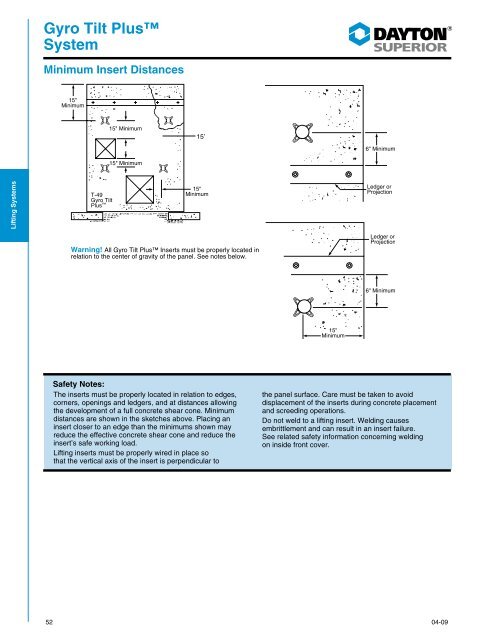
Gyro Tilt PlusSystemMinimum Insert Distances15"Minimum15" Minimum15’15" MinimumLifting SystemsCoil InsertsT-49Gyro TiltPlus 15"MinimumWarning! All Gyro Tilt Plus Inserts must be properly located inrelation to the center of gravity of the panel. See notes below.Safety Notes:The inserts must be properly located in relation to edges,corners, openings and ledgers, and at distances allowingthe development of a full concrete shear cone. Minimumdistances are shown in the sketches above. Placing aninsert closer to an edge than the minimums shown mayreduce the effective concrete shear cone and reduce theinsert’s safe working load.Lifting inserts must be properly wired in place sothat the vertical axis of the insert is perpendicular tothe panel surface. Care must be taken to avoiddisplacement of the inserts during concrete placementand screeding operations.Do not weld to a lifting insert. Welding causesembrittlement and can result in an insert failure.See related safety information concerning weldingon inside front cover.52 04-09
Tilt-Up 3Lifting SystemTILT-UP 3 LIFTING SYSTEMThe Dayton Superior Tilt-Up 3 Lifting System is a quality high strength, economical method for lifting, handling and placingconcrete tilt-up wall panels. The System features hardware applicable to face lift and edge lift applications.T-90-F Face Lift InsertThe Dayton Superior T-90-F Face Lift Insert is furnishedas an assembly, complete with a strong forged-foot anchor,wide-spread stable plastic base and plastic locator setting plug.The T-90-F insert is easy to position and tie into the rebar mat,plus an optional rebar clip is available to facilitate tying the insertto the mat.To Order:Specify: (1) quantity, (2) name,(3) panel structural thickness.Example:150 T-90-F Tilt-Up 3 Face Lift Inserts,7” panel structural thickness.Lifting SystemsCoil InsertsT-90-F Face Lift Insert Selection ChartT-90-F Face Lift Insert AssemblyStructuralPanelThicknessInsertSafe WorkingLoad5" 5-1/2" 6" 6-1/4"8,000 lbs. 10,000 lbs. 12,000 lbs. 12,500 lbs.6-1/2" 7" 7-1/4" 7-1/2" 8"13,000 lbs. 15,000 lbs. 15,000 lbs. 15,000 lbs. 15,000 lbs.Safe working load provides a safety factor of approximately 2 to 1 in 2,500 psi normal weight concrete.DO NOT use with top seeded aggregate 1/2” or larger as aggregate may “pop out” during the erection process, resulting in a reduced insertsafe working load.T-90-C Tilt-Up 3 Rebar ClipThe T-90-C Tilt-Up 3 Rebar Clip is available to provide aquick, positive method of fastening the T-90-F insert to therebar mat. The clip slips onto the body of the anchor where it“floats” with any movement of the rebar mat. Thus, preventingmisalignment of the insert due to fluctuations of the rebar mat.T-90-C Rebar Clips should be included when ordering T-90-FFace Lift Inserts.T-90-C Rebar ClipTo Order:Specify: (1) quantity, (2) name,(3) panel structural thickness.Example:150 T-90-F Tilt-Up 3 Face Lift Insertswith T-90-C Rebar Clip, 7” panelstructural thickness.04-0953
- Page 4 and 5: 2 02-09
- Page 6: General and TechnicalInformationGen
- Page 11 and 12: General andTechnical InformationThr
- Page 15 and 16: General andTechnical InformationBon
- Page 17 and 18: Panel ErectionInformationPanel Anal
- Page 19 and 20: Panel ErectionInformationStress Tab
- Page 21 and 22: Panel ErectionInformationStrongback
- Page 23 and 24: Panel ErectionInformationonto the s
- Page 25 and 26: Panel ErectionInformationStandard R
- Page 27 and 28: Panel ErectionInformationBrace and
- Page 29 and 30: Dayton SuperiorLifting SystemsDayto
- Page 31 and 32: SuperiorLifting SystemMinimum Inser
- Page 33 and 34: SuperiorLifting SystemT-110 Superio
- Page 35 and 36: Ground Release IISystemT-41 Ground
- Page 37 and 38: Ground Release IISystemHow to use t
- Page 39 and 40: Ground Release IISystemT-42 Double
- Page 41 and 42: Ground Release IISystemHow to use t
- Page 43 and 44: Ground Release IISystemP-52 Swift L
- Page 45 and 46: Ground Release IISystemHow To Insta
- Page 47 and 48: Ground Release IISystemP-60 Swift L
- Page 49 and 50: Gyro Tilt PlusSystemGyro Tilt Plus
- Page 51 and 52: Gyro Tilt PlusSystemT-50 Gyro Tilt
- Page 53: Gyro Tilt PlusSystemHow to Remove t
- Page 57 and 58: Tilt-Up 3Lifting SystemHow to Remov
- Page 59 and 60: Tilt-Up 3Lifting SystemMinimum Inse
- Page 61 and 62: Coil InsertsT-2 Double Pick-up Inse
- Page 63 and 64: Coil InsertsHow to use Coil Face In
- Page 65 and 66: Coil InsertsTotal System and Safe W
- Page 67 and 68: Coil InsertsT-8 Lifting Angle• De
- Page 69 and 70: Strongback SystemStrongbacksWhen op
- Page 71 and 72: Strongback SystemT-13-D Strongback
- Page 73 and 74: Strongback SystemT-63 Aluminum Stro
- Page 75 and 76: Bracing InformationBrace LoadingBra
- Page 77 and 78: Bracing InformationBrace to Floor S
- Page 79 and 80: Bracing InformationKnee, Lateral an
- Page 81 and 82: Bracing InformationBracing to Cylin
- Page 83 and 84: Bracing InformationT-13 COIL-ANCHOR
- Page 85 and 86: Bracing InformationT-4 Brace Anchor
- Page 87 and 88: Bracing InformationBrace Length and
- Page 89 and 90: Sandwich PanelConnectorsP-24 Delta
- Page 91 and 92: Sandwich PanelConnectorsDelta Tie I
- Page 93 and 94: Form LinersWhen it is time to choos
- Page 95 and 96: Form LinersWood Patterns4" Wide Age
- Page 97 and 98: Form LinersBlock PatternsBrick Patt
- Page 99 and 100: Form LinersStone PatternsRugged Fla
- Page 101 and 102: Form LinersVinyltite1.500" 1.500"0.
- Page 103 and 104: Form LinersApplication GuideTilt-Up
Gyro Tilt PlusSystemMinimum Insert Distances15"Minimum15" Minimum15’15" MinimumLifting SystemsCoil InsertsT-49Gyro TiltPlus 15"MinimumWarning! All Gyro Tilt Plus Inserts must be properly located inrelation to the center of gravity of the panel. See notes below.Safety Notes:The inserts must be properly located in relation to edges,corners, openings and ledgers, and at distances allowingthe development of a full concrete shear cone. Minimumdistances are shown in the sketches above. Placing aninsert closer to an edge than the minimums shown mayreduce the effective concrete shear cone and reduce theinsert’s safe working load.Lifting inserts must be properly wired in place sothat the vertical axis of the insert is perpendicular tothe panel surface. Care must be taken to avoiddisplacement of the inserts during concrete placementand screeding operations.Do not weld to a lifting insert. Welding causesembrittlement and can result in an insert failure.See related safety information concerning weldingon inside front cover.52 04-09


