

BT 80 100 Series 300 301 Commercial Gas Manual 197569-000 ...
BT 80 100 Series 300 301 Commercial Gas Manual 197569-000 ...
BT 80 100 Series 300 301 Commercial Gas Manual 197569-000 ...

You also want an ePaper? Increase the reach of your titles
YUMPU automatically turns print PDFs into web optimized ePapers that Google loves.
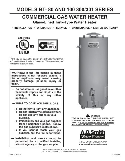
MODELS <strong>BT</strong>- <strong>80</strong> AND <strong>100</strong> <strong>300</strong>/<strong>301</strong> SERIESCOMMERCIAL GAS WATER HEATERGlass-Lined Tank-Type Water Heater• INSTALLATION • OPERATION • SERVICE • MAINTENANCE • LIMITED WARRANTYThank you for buying this energy efficient water heater fromA.O. Smith Water Products Company. We appreciate yourconfidence in our products.CAUTIONTEXT IN BLACK BOLD TYPE OR UNDERLINEDCONTAINS INFORMATION RELATIVE TO YOURSAFETY. PLEASE READ THOROUGHLY BEFOREINSTALLING AND USING THIS APPLIANCE.McBEE, SOUTH CAROLINA, USAwww.aosmithwaterheaters.comPLACE THESE INSTRUCTIONS ADJACENT TO HEATERAND NOTIFY OWNER TO KEEP FOR FUTURE REFERENCE.PRINTED 0107 <strong>197569</strong>-<strong>000</strong>1
ROUGH-IN DIMENSIONSFIGURE 1.DIMENSIONSModel Units A B C D E F G H J K L M<strong>BT</strong>-<strong>80</strong> Inches 61 1/8 58 1/2 29 11/16 26 1/2 15 3/16 4 14 1/2 16 1 1/4 1 1/2 11 15/16Natural & LP C M 155.25 148.6 75.4 67.3 38.6 10.2 39.4 40.6 3.2 NPT NPT 30.3<strong>BT</strong>-<strong>100</strong> Inches 68 5/8 66 1/2 30 15/16 27 3/4 15 3/16 4 15 3/4 16 1 1/4 1 1/4 1/2 11 15/16Natural & LP CM 174.3 168.9 78.59 70.5 38.6 10.2 40.0 40.6 3.2 NPT NPT 30.3RECOVERY RATINGSInput Approx. Approx.Model Rating Rating Gal. Liter Temp. C° 17 22 28 33 39 44 50 56 61 67 72 78Btu/Hr kW Cap. Cap. Rise F° 30 40 50 60 70 <strong>80</strong> 90 <strong>100</strong> 110 120 130 140<strong>BT</strong>- <strong>80</strong> 75,<strong>100</strong> 22.0 74 2<strong>80</strong> GPH 243 182 146 121 104 91 81 73 66 61 56 52LPH 916 686 550 456 392 343 305 275 249 230 211 196<strong>BT</strong> -<strong>100</strong> 75,<strong>100</strong> 22.0 98 371 GPH 243 182 146 121 104 91 81 73 66 61 56 52LPH 916 686 550 456 392 343 305 275 249 230 211 196Recovery ratings based on <strong>80</strong>% thermal efficiency.FOREWORDThe design of models <strong>BT</strong>-<strong>80</strong> and <strong>100</strong> comply with the current editionof ANSI Z21.10.3-CSA 4.3 as automatic storage or automaticcirculating tank type water heaters.Installation diagrams are found in this manual. These diagramswill serve to provide the installer with a reference for the materialsand method of piping necessary. It is highly essential that all waterand gas piping be installed as shown on the diagrams.In addition to these instructions, the equipment shall be installed inaccordance with those installation regulations in force in the localarea where the installation is to be made. These shall be carefullyfollowed in all cases. Authorities having jurisdiction should beconsulted before installations are made.In the absence of local codes, the installation must comply with thecurrent edition of the National Fuel <strong>Gas</strong> Code, ANSI Z223.1/NFPA 54or the Natural <strong>Gas</strong> and Propane Installation Code CAN/CSA-B149.1.These documents are available from the Canadian StandardsAssociation, 8501 East Pleasant Valley Road, Cleveland, OH 44131.2
TABLE OF CONTENTSPageROUGH-IN DIMENSIONS ................................................................... 2FOREWORD ........................................................................................ 2GENERAL SAFETY INFORMATION ................................................... 3-4Precautions ....................................................................................... 3Chemical Vapor Corrosion ............................................................... 3Improper Combustion ....................................................................... 3Liquid Petroleum Models .................................................................. 3-4Extended Non-use Periods .............................................................. 4Insulation Blankets ........................................................................... 4Circulating Pump .............................................................................. 4INSTALLATION INSTRUCTIONS ........................................................ 4-9Required Ability ................................................................................. 4Locating The Heater ......................................................................... 4-5High Altitude Installations ................................................................. 5Clearances ....................................................................................... 5Hard Water ....................................................................................... 5Air Requirements .............................................................................. 5-6Water (Potable) Heating and Space Heating ................................... 6Venting .............................................................................................. 6-7Thermometers (Not Supplied) .......................................................... 7Relief Valve ....................................................................................... 7<strong>Gas</strong> Piping ........................................................................................ 8-9<strong>Gas</strong> Pressure Regulator ................................................................... 9GENERAL SAFETYINFORMATIONPRECAUTIONSDO NOT USE THIS APPLIANCE IF ANY PART HAS BEEN UNDERWATER. Immediately call a qualified service technician to inspectthe appliance and to replace any part of the control system and anygas control which has been under water.IF THE UNIT IS EXPOSED TO THE FOLLOWING, DO NOTOPERATE HEATER UNTIL ALL CORRECTIVE STEPS HAVE BEENMADE BY A QUALIFIED SERVICEMAN.1. EXTERNAL FIRE.2. DAMAGE.3. FIRING WITHOUT WATER.4. SOOTINGCHEMICAL VAPOR CORROSIONWARNINGCORROSION OF THE FLUEWAYS AND VENT SYSTEM MAYOCCUR IF AIR FOR COMBUSTION CONTAINS CERTAINCHEMICAL VAPORS. SUCH CORROSION MAY RESULT INFAILURE AND RISK OF ASPHYXIATION.Spray can propellants, cleaning solvents, refrigerator and airconditioning refrigerants, swimming pool chemicals, calcium andsodium chloride (water softener salt), waxes, and process chemicalsare typical compounds which are potentially corrosive. Do not storeproducts of this sort near the heater. Also, air which is brought incontact with the heater should not contain any of these chemicals.If necessary, uncontaminated air should be obtained from remoteor outside sources. The limited warranty is voided when failure ofwater heater is due to a corrosive atmosphere. (Refer to the limitedwarranty for complete terms and conditions.)PageOPERATION ........................................................................................ 9-13To Operate The Water Heater ......................................................... 9Purging ............................................................................................ 9Lighting Instructions ........................................................................ 10-11Temperature Regulation .................................................................. 12Check Venting ................................................................................. 12-13High Temperature Limit Switch ....................................................... 13SERVICE INFORMATION ................................................................... 13-14Pilot and Main Burner ...................................................................... 13Checking <strong>Gas</strong> Input ......................................................................... 13-14Vent System .................................................................................... 14Relief Valve ...................................................................................... 14Hot Water Odor ............................................................................... 14Anode Rod Inspection ..................................................................... 14Winter Protection ............................................................................. 14Replacement Parts .......................................................................... 14PREVENTIVE MAINTENANCE ..........................................................15-16Recommended Procedure For Periodic Removal Of LimeDeposits From Tank Type <strong>Commercial</strong> Water Heaters .................. 15Deliming Solvents ............................................................................ 15Tank Cleanout Procedure ................................................................15-16CHECKLIST......................................................................................... 16-17LIMITED WARRANTY .......................................................................... 18IMPROPER COMBUSTIONWARNINGATTIC AND/OR EXHAUST FANS OPERATING ON THE PREMISESWITH A WATER HEATER CAN RESULT IN CARBON MONOXIDEPOISONING AND DEATH.OPERATION OF THESE FANS CAN PRODUCE A NEGATIVEDRAFT IN THE AREA OF THE WATER HEATER PREVENTINGTHE PRODUCTS OF COMBUSTION FROM EXHAUSTINGTHROUGH THE CHIMNEY OR VENT PIPE.The venting of the water heater should be inspected by a qualifiedservice technician at the time of installation and periodically thereafterto ensure a down-draft condition does not exist.DO NOT OBSTRUCT THE FLOW OF COMBUSTION ANDVENTILATING AIR. ADEQUATE AIR FOR COMBUSTION ANDVENTILATION MUST BE PROVIDED FOR SAFE OPERATION.LIQUID PETROLEUM MODELSWater heaters for propane or liquefied petroleum gas (LPG)are different from natural gas models. A natural gas heater willnot function safely on LP gas and no attempt should be madeto convert a heater from natural gas to LP gas.LP gas must be used with great caution. It is highly explosiveand heavier than air. It collects first in the low areas making itsodor difficult to detect at nose level. If LP gas is present oreven suspected, do not attempt to find the cause yourself. Goto a neighbor's house, leaving your doors open to ventilate thehouse, then call your gas supplier or service agent. Keep areaclear until a service call has been made.At times you may not be able to smell an LP gas leak. Onecause is odor fade, which is a loss of the chemical odorant thatgives LP gas its distinctive smell. Another cause can be yourphysical condition, such as having a cold or diminishing senseof smell with age. For these reasons, the use of a propane gasdetector is recommended.3
IF YOU EXPERIENCE AN OUT-OF-GAS SITUATION, DO NOT TRYTO RELIGHT APPLIANCES YOURSELF, ask your LP delivery personto relight pilots for you. Only trained LP professionals should conductthe required safety checks in accordance with industry standards.EXTENDED NON-USE PERIODSWARNINGHYDROGEN GAS CAN BE PRODUCED IN A HOT WATERSYSTEM SERVED BY THIS HEATER THAT HAS NOT BEEN USEDFOR A LONG PERIOD OF TIME (GENERALLY TWO WEEKS ORMORE). HYDROGEN GAS IS EXTREMELY FLAMMABLE. Toreduce the risk of injury under these conditions, it is recommendedthat the hot water faucet be opened for several minutes at the kitchensink before using any electrical appliance connected to the hot watersystem. If hydrogen is present, there will probably be an unusualsound such as air escaping through the pipe as the water begins toflow. THERE SHOULD BE NO SMOKING OR OPEN FLAME NEARTHE FAUCET AT THE TIME IT IS OPEN.INSULATION BLANKETSInsulation blankets available to the general public for external useon gas water heaters are not approved for use on your A.O. Smithwater heater. The purpose of an insulation blanket is to reducethe standby heat loss encountered with storage tank waterheaters. Your A.O. Smith water heater meets or exceeds theASHRAE/IES 90.1b-1999 standards with respect to insulation andstandby loss requirement making an insulation blanket unnecessary.WARNINGShould you choose to apply an insulation blanket to this heater,you should follow these instructions. Failure to follow theseinstructions can result in fire, asphyxiation , serious personalinjury or death.• Do not apply insulation to the top of the water heater, asthis will interfere with safe operation of the draft hood.• Do not cover the outer door, thermostat or temperature &pressure relief valve.• Do not allow insulation to come within 2" (5cm) of the floorto prevent blockage of combustion air flow to the burner.• Do not cover the instruction manual. Keep it on the side ofthe water heater or nearby for future reference.• Do obtain new warning and instruction labels from A.O. Smithfor placement on the blanket directly over the existing labels.• Do inspect the insulation blanket frequently to make certainit does not sag, thereby obstructing combustion air flow.CIRCULATING PUMPA circulating pump is used when a system requires a circulatingloop or there is a storage tank used in conjunction with the heater.Install the system in accordance with the current edition of theNational Electrical Code ANSI/NFPA No. 70 or the CanadianElectrical Code CSA C22.1.Only all bronze circulators are used with commercial water heaters.Although circulators are oiled and operated by the manufacturersome circulators must be oiled again before operating. Please referto manufacturer’s instructions.INSTALLATION INSTRUCTIONSREQUIRED ABILITYINSTALLATION OR SERVICE OF THIS WATER HEATERREQUIRES ABILITY EQUIVALENT TO THAT OF A LICENSEDTRADESMAN IN THE FIELD INVOLVED. PLUMBING, AIR SUPPLY,VENTING AND GAS SUPPLY WORK ARE REQUIRED.GENERALThe heater is designed to operate on natural or propane gases.HOWEVER, MAKE SURE the gas on which the heater will operateis the same as that specified on the heater model and rating plate.LOCATING THE HEATERWhen installing the heater, consideration must be given to properlocation. Location selected should be as close to the stack orchimney as practicable, with adequate air supply and as centralizedwith the piping system as possible.WARNINGTHERE IS A RISK IN USING FUEL BURNING APPLIANCES SUCHAS GAS WATER HEATERS IN ROOMS, GARAGES OR OTHERAREAS WHERE GASOLINE, OTHER FLAMMABLE LIQUIDS ORENGINE DRIVEN EQUIPMENT OR VEHICLES ARE STORED,OPERATED OR REPAIRED. FLAMMABLE VAPORS ARE HEAVYAND TRAVEL ALONG THE FLOOR AND MAY BE IGNITED BY THEHEATER’S PILOT OR MAIN BURNER FLAMES CAUSING FIREOR EXPLOSION. SOME LOCAL CODES PERMIT OPERATIONOF GAS APPLIANCES IF INSTALLED 18" (46CM) OR MOREABOVE THE FLOOR. THIS MAY REDUCE THE RISK IF LOCATIONIN SUCH AN AREA CANNOT BE AVOIDED.DO NOT INSTALL THIS WATER HEATER DIRECTLY ON ACARPETED FLOOR. A FIRE HAZARD MAY RESULT. Instead thewater heater must be placed on a metal or wood panel extendingbeyond the full width and depth by at least 3" (76.2mm) in anydirection. If the heater is installed in a carpeted alcove or closet, theentire floor shall be covered by the panel. Also, see the drainrequirements.THIS HEATER SHALL BE LOCATED OR PROTECTED SO IT ISNOT SUBJECT TO PHYSICAL DAMAGE BY A MOVING VEHICLE.WARNINGFLAMMABLE ITEMS, PRESSURIZED CONTAINERS OR ANYOTHER POTENTIAL FIRE HAZARDOUS ARTICLES MUSTNEVER BE PLACED ON OR ADJACENT TO THE HEATER. OPENCONTAINERS OF FLAMMABLE MATERIAL SHOULD NOT BESTORED OR USED IN THE SAME ROOM WITH THE HEATER.THE HEATER MUST NOT BE LOCATED IN AN AREA WHERE ITWILL BE SUBJECT TO FREEZING.THE HEATER SHOULD BE LOCATED IN AN AREA WHERELEAKAGE FROM THE HEATER OR CONNECTIONS WILL NOTRESULT IN DAMAGE TO THE ADJACENT AREA OR TO LOWERFLOORS OF THE STRUCTURE.WHEN SUCH LOCATIONS CANNOT BE AVOIDED, A SUITABLEDRAIN PAN SHOULD BE INSTALLED UNDER THE HEATER.Such pans should be fabricated with sides at least 2" (5cm) deep,with length and width at least 2" (5cm) greater than the diameter ofthe heater and must be piped to an adequate drain. The pan mustnot restrict combustion air flow.4
Drain pans suitable for these heaters are available from yourdistributor or A. O. Smith Water Products Company, 500 TennesseeWaltz Parkway, Ashland City, TN 37015.Water heater life depends upon water quality, water pressure and theenvironment in which the water heater is installed. Water heaters aresometimes installed in locations where leakage may result in propertydamage, even with the use of a drain pan piped to a drain. However,unanticipated damage can be reduced or prevented by a leak detectoror water shutoff device used in conjunction with a piped drain pan.These devices are available from some plumbing supply wholesalersand retailers, and detect and react to leakage in various ways:• Sensors mounted in the drain pan that trigger an alarm or turn offthe incoming water to the water heater when leakage is detected.• Sensors mounted in the drain pan that turn off the water supplyto the entire home when water is detected in the drain pan.• Water supply shutoff devices that activate based on the waterpressure differential between the cold water and hot water pipesconnected to the water heater.• Devices that will turn off the gas supply to a gas water heaterwhile at the same time shutting off its water supply.For appliance installation locations with elevations above 2<strong>000</strong>'(610m), refer to HIGH ALTITUDE INSTALLATIONS section of thismanual for input reduction procedure.HIGH ALTITUDE INSTALLATIONSWARNINGINSTALLATIONS ABOVE 2<strong>000</strong>' (610m) REQUIRE REPLACEMENTOF THE BURNER ORIFICE IN ACCORDANCE WITH SECTION8.1.2 OF THE NATIONAL FUEL GAS CODE (ANSI Z223.1). FORCANADIAN INSTALLATIONS CONSULT THE NATURAL GAS ANDPROPANE INSTALLATION CODE CAN/CSA-B149.1. FAILURE TOREPLACE THE ORIFICE WILL RESULT IN IMPROPER ANDINEFFICIENT OPERATION OF THE APPLIANCE RESULTING INTHE PRODUCTION OF INCREASED LEVELS OF CARBONMONOXIDE GAS IN EXCESS OF SAFE LIMITS WHICH COULDRESULT IN SERIOUS PERSONAL INJURY OR DEATH.specified on the heater rating plate is not permitted.The input reduction is primarily achieved by reducing the size ofthe main burner orifices. To do this, the main burner orifices requirereplacement with orifices sized for the particular installationelevation. Correct orifice sizing and parts may be obtained fromA.O. Smith Water Products Company. When ordering, be sure tostate the model number and the altitude of the location where thewater heater is being installed.Upon completion of derating of the heater, adjustment to the gaspressure regulator may be required. See CHECKING THE INPUTsection in this manual for inlet and manifold pressure requirements.Also due to the input rating reduction required at high altitudes, therecovery rating of the appliance is also reduced and should becompensated for in the sizing of the equipment for application.CLEARANCESThese heaters are approved for installation on combustible flooringin a closet having a ceiling 12" (30.5cm) above top cover and withclearances to combustible construction of 6" (15.2cm) from flue orvent connector, 0" (0cm) at the sides and rear and 4" (10.1cm) tofront to prevent a possible fire hazard condition. A minimum of 4"(10.1cm) shall be allowed for installation of serviceable parts.HARD WATERWhere hard water conditions exist, water softening or the threshold typeof water treatment is recommended. This will protect the dishwashers,coffee urns, water heaters, water piping and other equipment.See PREVENTIVE MAINTENANCE section for details of tankcleanout procedure.AIR REQUIREMENTSREFER TO THE CURRENT EDITION OF THE NATIONAL FUELGAS CODE ANSI Z223.1/NFPA 54.You should contact your gas supplier for any specific changes whichmay be required in your area.As elevation above sea level is increased, there is less oxygen percubic foot of air. Therefore, the heater input rate should be reducedat high altitudes for satisfactory operation with the reduced oxygensupply. Failure to make this reduction would result in an overfiringof the heater causing sooting, poor combustion and/or unsatisfactoryheater performance.U.S. REQUIREMENTSRatings specified by manufacturers for most appliances apply forelevations up to 2<strong>000</strong> feet (610m). For elevations above 2<strong>000</strong> feet(610m), ratings must be reduced at the rate of 4% for each <strong>100</strong>0 feet(305m) above sea level. For example, if a heater is rated at 75,<strong>100</strong>Btu/Hr (22.0 kW) at sea level, to rate the heater at 4<strong>000</strong> feet (1219m),you subtract 4 (once for each thousand feet) x 0.04 (4% inputreduction) x 75,<strong>100</strong> Btu/Hr (original rating) from the original rating.Therefore, to calculate the input rating at 4<strong>000</strong> feet (1219m): 4 x 0.04x 75,<strong>100</strong> Btu/Hr = 12,016 Btu/Hr (3.5 kW); 75,<strong>100</strong> Btu/Hr (22.0 kW) -12,016 Btu/Hr (3.5 kW) = 63,084 Btu/Hr (18.5 kW). At 6<strong>000</strong> feet(1829m) the correct input rating should be 57,076 Btu/Hr (16.7 kW).CANADIAN REQUIREMENTSAppliances with inputs up to and including 400,<strong>000</strong> <strong>BT</strong>U (117.1 kwh)must be factory equipped with orifices for operation at specificelevations. Standard (sea level) orifices permit operation up to 2<strong>000</strong>'(610m) elevation. For operation between 2<strong>000</strong>' (610m) and 4500'(1370m) specify "HIGH ALTITUDE OPERATION" when ordering theheater(s). For operation above 4500' (1370m) consult factory beforeordering. Field conversion for operation at altitudes other than that5KEEP APPLIANCE AREA CLEAR AND FREE OF COMBUSTIBLEMATERIALS, GASOLINE AND OTHER FLAMMABLES, VAPORSAND LIQUIDS.DO NOT OBSTRUCT THE FLOW OF COMBUSTION ORVENTILATING AIR.WARNINGFOR SAFE OPERATION PROVIDE ADEQUATE AIR FORCOMBUSTION AND VENTILATION. AN INSUFFICIENT SUPPLY OFAIR WILL CAUSE RECIRCULATION OF COMBUSTION PRODUCTSRESULTING IN AIR CONTAMINATION THAT MAY BE HAZARDOUSTO LIFE. SUCH A CONDITION OFTEN WILL RESULT IN A YELLOW,LUMINOUS BURNER FLAME, CAUSING CARBONING OR SOOTINGOF THE COMBUSTION CHAMBER, BURNERS AND FLUE TUBESAND CREATES A RISK OF ASPHYXIATION.Where an exhaust fan is supplied in the same room with a heater,sufficient openings for air must be provided in the walls.UNDERSIZED OPENINGS WILL CAUSE AIR TO BE DRAWN INTOTHE ROOM THROUGH THE CHIMNEY, CAUSING POORCOMBUSTION. SOOTING MAY RESULT IN SERIOUS DAMAGETO THE HEATER AND RISK OF FIRE OR EXPLOSION.UNCONFINED SPACEIn buildings of conventional frame, brick, or stone construction,unconfined spaces may provide adequate air for combustion,ventilation and draft hood dilution.If the unconfined space is within a building of tight construction(buildings using the following construction: weather stripping, heavy
insulation, caulking, vapor barrier, etc.), air for combustion, ventilationand draft hood dilution must be obtained from outdoors. Theinstallation instructions for confined spaces in tightly constructedbuildings must be followed to ensure adequate air supply.CONFINED SPACEWhen drawing combustion and dilution air from inside aconventionally constructed building to a confined space, such aspace shall be provided with two permanent openings, ONE IN ORWITHIN 12 " (305mm) OF THE ENCLOSURE TOP AND ONE INOR WITHIN 12" (305mm) OF THE ENCLOSURE BOTTOM. Eachopening shall have a free area of at least one square inch per <strong>100</strong>0Btu/Hr (2203mm 2 /kW) of the total input of all appliances in theenclosure, but not less than <strong>100</strong> square inches (645cm 2 ).If the confined space is within a building of tight construction, airfor combustion, ventilation, and draft hood dilution must be obtainedfrom outdoors. When directly communicating with the outdoors orcommunicating with the outdoors through vertical ducts, twopermanent openings, located in the above manner, shall beprovided. Each opening shall have a free area of not less thanone square inch per 4<strong>000</strong> Btu/Hr (551mm 2 /kW) of the total input ofall appliances in the enclosure. If horizontal ducts are used, eachopening shall have a free area of not less than one square inchper 2<strong>000</strong> Btu/Hr (1102mm 2 /kW) of the total input of all appliancesin the enclosure.WATER (POTABLE) HEATING AND SPACEHEATING1. All piping components connected to this unit for space heatingapplications shall be suitable for use with potable water.2. Toxic chemicals, such as those used for boiler treatment, shallNEVER be introduced into this system.3. This unit may NEVER be connected to any existing heatingsystem or component(s) previously used with a non-potablewater heating appliance.4. When the system requires water for space heating attemperatures higher than required for domestic water purposes,a tempering valve must be installed, see Figure 4.CAUTIONA closed system will exist if a check valve (without bypass),pressure reducing valve (without bypass), or a water meter(without bypass) is installed in the cold water line between thewater heater and street main (or well).Excessive pressure may develop in such closed systems,causing premature tank failure or intermittent relief valveoperation. This is not a warranty failure. An expansion tank ora similar device is required in the inlet supply line between theappliance and the meter or valve to compensate for the thermalexpansion of the water.Heater must be protected from freezing downdrafts.Remove all soot or other obstructions from the chimney that willretard a free draft.Type B venting is recommended with these heaters.This water heater must be vented in compliance with all local codes,the current edition of the National Fuel <strong>Gas</strong> Code ANSI-Z223.1 orthe Natural <strong>Gas</strong> and Propane Installation Code CAN/CSA-B149.1.If any part of the vent system is exposed to ambient temperaturesbelow 35° F (2° C) it must be insulated to prevent condensation.• Do not connect the heater to a common vent or chimney with anyoil-fired or solid fuel burning equipment. This practice is prohibitedby many local building codes as is the practice of venting gasfired equipment to the duct work of ventilation systems.DRAFT HOODFIGURE 2.The draft hood furnished with this heater must be installed withoutalteration. Provision must be made if it is installed in confined spaceor a small room to accommodate draft hood spillage and avoid risksdescribed in previous steps. The upper air opening called for in theAIR REQUIREMENTS section of this manual is for this purpose.Locate the 3 brackets and 6 screws in the installation instruction bag.Secure each bracket to the draft hood leg with the screws furnished.Place the draft hood on the water heater so that legs of the draft hoodfit into the slots on the jacket top, see Figure 3. Once the draft hood(with brackets attached) is in place, drill a small pilot hole throughbracket hole into the jacket top. WARNING, DO NOT PENETRATETHE JACKET TOP BY MORE THAN 1/4". Secure the brackets tothe jacket top with the screws furnished, see Figure 3.SYSTEM CONNECTIONSThe system installation must conform to these instructions and tothe local code authority having jurisdiction. Good practice requiresthat all heavy piping be supported.VENTINGWARNINGTHE INSTRUCTIONS IN THIS SECTION ON VENTING MUSTBE FOLLOWED TO AVOID CHOKED COMBUSTION ORRECIRCULATION OF FLUE GASES. SUCH CONDITIONS CAUSESOOTING OR RISKS OF FIRE AND ASPHYXIATION.FIGURE 3.6
VENT CONNECTIONVent connections must be made to an adequate stack or chimney.Size and install proper size vent pipe. Do not reduce pipe size toless than that of the draft hood outlet.Horizontal runs of vent pipe must have a minimum upward slopetoward the chimney of 1/4 inch per foot. Dampers or otherobstructions must not be installed in between the heater and thedraft hood. Be sure that the vent pipe does not extend beyond theinside wall of the chimney.Where a continuous or intermittent back draft is found to exist, thecause must be determined and corrected. A special vent cap maybe required. If the back draft cannot be corrected by the normalmethods or if a suitable draft cannot be obtained, a blower type fluegas exhauster must be employed to assure proper venting andcorrect combustion.THERMOMETERS (Not Supplied)Thermometers should be obtained and field installed as shown,see Figure 4.Thermometers are installed in the system as a means of detectingthe temperature of the outlet water supply.RELIEF VALVEThis water heater is equipped with a combination temperaturepressurerelief valve that complies with the standard for relief valvesfor hot water supply system, ANSI Z21.22/CSA 4.4. FOR SAFEOPERATION OF THE WATER HEATER, THE RELIEF VALVE(S)MUST NOT BE REMOVED OR PLUGGED.ASME ratings cover pressure relief capacities. ANSI ratings coverrelease rate with temperature actuation.In addition to the appliance relief valve, each remote storage tankwhich may be used in conjunction with this appliance shall also beinstalled with a properly sized, rated and approved combinationtemperature (ANSI) and pressure (ASME) relief valve(s).WARNINGTHE PURPOSE OF RELIEF VALVE IS TO AVOID EXCESSIVEPRESSURE OR TEMPERATURE INTO THE STEAM RANGE,WHICH MAY CAUSE SCALDING AT FIXTURES, TANKEXPLOSION, SYSTEM OR HEATER DAMAGE. NO VALVE IS TOBE PLACED BETWEEN THE RELIEF VALVE AND TANK.Your local code authority may have other specific relief valverequirements.A DRAIN LINE MUST BE CONNECTED TO THE RELIEF VALVETO DIRECT DISCHARGE TO A SAFE LOCATION TO AVOIDSCALDING OR WATER DAMAGE. THIS LINE MUST NOT BEREDUCED FROM THE SIZE OF THE VALVE OUTLET AND MUSTNOT CONTAIN VALVES, RESTRICTIONS NOR SHOULD IT BELOCATED IN FREEZING AREAS. DO NOT THREAD OR CAP THEEND OF THIS LINE. RESTRICTED OR BLOCKED DISCHARGEWILL DEFEAT THE PURPOSE OF THE VALVE AND IS UNSAFE.DISCHARGE LINE SHALL BE INSTALLED TO ALLOW COMPLETEDRAINAGE OF BOTH THE VALVE AND LINE.See SERVICE INFORMATION section for procedure andprecautions.The type, size and location of the relief valves must be in accordancewith local codes. The locations of the relief valves shown in theinstallation diagrams are typical. The heater has a factory installedhigh temperature limit switch.For circulating heaters, the separate storage vessel must have atemperature and pressure relief valve installed. This valve shallcomply with the standard for relief valves and automatic gas shutoffdevices for hot water supply systems.Cold water inlet lines to heater should be installed as shown inorder to minimize gravity circulation of hot water to building coldwater lines.MIXING VALVE APPLICATIONFOR TWO TEMPERATURE WATERSINGLE TEMPERATUREINSERT B - VACUUMRELIEF VALVE*INSTALL PERLOCAL CODESCIRCULATING RETURN LINE CONNECTIONSTEMPERED WATER LOOP, IF USED, CONNECT TO POINT"A". STORED TEMPERATURE WATER LOOP, IF USED,CONNECT TO COLD WATER INLET.CAUTION: IF BUILDING COLD WATER SUPPLY HAS A BACK-FLOW PREVENTER, CHECK VALVE OR WATER METERWITH CHECK VALVE, PROVISIONS FOR THERMALEXPANSION OF WATER IN THE HOT WATER SYSTEM MUSTBE PROVIDED.FIGURE 47INSTALL THERMAL EXPANSIONTANK OR DEVICE IF CHECK VALVEOR PRESSURE REDUCINGVALVE IS USED IN SUPPLYWARNINGTEMPERATURE SETTING SHOULD NOT EXCEED SAFEUSE TEMPERATURE AT FIXTURES, SEETEMPERATURE REGULATION ON PAGE 12. IF HIGHERPREHEAT TEMPERATURES ARE NECESSARY TOO<strong>BT</strong>AIN ADEQUATE BOOSTER OUTPUT, ADD AN ANTI-SCALD VALVE FOR HOT WATER SUPPLIED TOFIXTURES.
GAS PIPINGContact your local gas service company to ensure that adequategas service is available and to review applicable installation codesfor your area.Size the main gas line in accordance with Table 1. The figures shownare for straight lengths of pipe at 0.5 in. W.C. pressure drop, whichis considered normal for low pressure systems. Note: Fittings suchas elbows, tees and line regulators will add to the pipe pressuredrop. Also refer to the current editions of the National Fuel <strong>Gas</strong>Code or Natural <strong>Gas</strong> and Propane Installation Code.WARNINGTHE HEATER IS NOT INTENDED FOR OPERATION AT HIGHERTHAN 14.0" W.C.(3.48 kPa) - NATURAL GAS OR 14.0" W.C. (3.48kPa) PROPANE GAS SUPPLY PRESSURE. EXPOSURE TOHIGHER SUPPLY PRESSURE MAY CAUSE DAMAGE TO THE GASVALVE WHICH COULD RESULT IN FIRE OR EXPLOSION. IFOVERPRESSURE HAS OCCURRED SUCH AS THROUGHIMPROPER TESTING OF GAS LINES OR EMERGENCYMALFUNCTION OF THE SUPPLY SYSTEM, THE GAS VALVEMUST BE CHECKED FOR SAFE OPERATION. MAKE SURE THATTHE OUTSIDE VENTS ON THE SUPPLY REGULATORS AND THESAFETY VENT VALVES ARE PROTECTED AGAINST BLOCKAGE.THESE ARE PARTS OF THE GAS SUPPLY SYSTEM, NOT THEHEATER. VENT BLOCKAGE MAY OCCUR DURING ICE STORMS.TABLE 1 - GAS SUPPLY LINE SIZES (IN INCHES)*MAXIMUM CAPACITY OF PIPE INCUBIC FEET PER HOURLENGTH NOMINAL IRON PIPE SIZES (INCHES)ININPUT IN THOUSANDS (<strong>BT</strong>U/HR)FEET 1/2" 3/4" 1" 1 1/4" 1 1/2" 2" 2 1/2" 3" 4"10 175 360 6<strong>80</strong> 1400 2<strong>100</strong> 3960 6<strong>300</strong> 1<strong>100</strong>0 2<strong>300</strong>020 120 250 465 950 1460 2750 4360 7700 15<strong>80</strong>030 97 200 375 770 11<strong>80</strong> 2200 3520 6250 12<strong>80</strong>040 82 170 320 660 990 1900 <strong>300</strong>0 5<strong>300</strong> 1090050 73 151 285 5<strong>80</strong> 900 16<strong>80</strong> 2650 4750 970060 66 138 260 530 810 1520 2400 4<strong>300</strong> 8<strong>80</strong>070 61 125 240 490 750 1400 2250 3900 8<strong>100</strong><strong>80</strong> 57 118 220 460 690 1<strong>300</strong> 2050 3700 750090 53 110 205 430 650 1220 1950 3450 7200<strong>100</strong> 50 103 195 400 620 1150 1850 3250 6700125 44 93 175 360 550 1020 1650 2950 6<strong>000</strong>150 40 84 160 325 500 950 1500 2650 5500175 37 77 145 <strong>300</strong> 460 850 1370 2450 5<strong>000</strong>200 35 72 135 2<strong>80</strong> 430 <strong>80</strong>0 12<strong>80</strong> 22<strong>80</strong> 4600LENGTH NOMINAL IRON PIPE SIZES (INCHES)ININPUT IN KWMETERS 1/2" 3/4" 1" 1 1/4" 1 1/2" 2" 2 1/2" 3" 4"3 51 105 199 410 615 1160 1845 3221 67356 35 73 142 278 428 <strong>80</strong>5 1277 2255 46269 28 59 110 225 346 644 1031 1830 374812 24 50 94 193 290 556 878 1552 319215 21 44 83 170 264 492 776 1391 284018 19 40 76 155 237 445 703 1259 257721 18 37 70 143 220 410 659 1142 237224 17 35 64 135 202 381 600 1083 219627 16 32 60 126 190 357 571 1010 210831 15 30 57 117 182 337 542 952 196238 13 27 51 105 161 299 483 864 175746 12 25 47 95 146 278 439 776 161053 11 23 42 88 135 249 401 717 146461 10 21 40 82 126 234 375 688 1347IT IS IMPORTANT TO GUARD AGAINST GAS VALVE FOULINGFROM CONTAMINANTS IN THE GAS WAYS. SUCH FOULINGMAY CAUSE IMPROPER OPERATION, FIRE OR EXPLOSION.IF COPPER SUPPLY LINES ARE USED THEY MUST BEINTERNALLY TINNED AND CERTIFIED FOR GAS SERVICE.BEFORE ATTACHING THE GAS LINE, BE SURE THAT ALL GASPIPE IS CLEAN ON THE INSIDE.TO TRAP ANY DIRT OR FOREIGN MATERIAL IN THE GAS SUPPLYLINE, A DIRT LEG (SOMETIMES CALLED SEDIMENT TRAP OR DRIPLEG) MUST BE INCORPORATED IN THE PIPING (SEE FIG. 5). THEDIRT LEG MUST BE READILY ACCESSIBLE AND NOT SUBJECTTO FREEZING CONDITIONS. INSTALL IN ACCORDANCE WITHRECOMMENDATIONS OF SERVING GAS SUPPLIERS. REFER TOTHE CURRENT EDITION OF THE NATIONAL FUEL GAS CODE ORNATURAL GAS AND PROPANE INSTALLATION CODE.To prevent damage, care must be taken not to apply too much torquewhen attaching gas supply pipe to gas valve inlet.Apply joint compounds (pipe dope) sparingly and only to the malethreads of pipe joints. Do not apply compounds to the first twothreads. Use compounds resistant to the action of liquefiedpetroleum gases.BEFORE PLACING THE HEATER IN OPERATION, CHECK FORGAS LEAKAGE. Use soap and water solution or other materialacceptable for the purpose in locating the leaks. DO NOT USEMATCHES, CANDLES, FLAME OR OTHER SOURCES OFIGNITION FOR THIS PURPOSE.DISCONNECT THE HEATER AND ITS MANUAL GAS SHUTOFFVALVE FROM THE GAS SUPPLY PIPING SYSTEM DURING ANYSUPPLY PRESSURE TESTING EXCEEDING 1/2 PSIG (3.45 kPa).GAS SUPPLY LINE MUST BE CAPPED WHEN DISCONNECTEDFROM THE HEATER FOR TEST PRESSURES OF 1/2 PSIG (3.45kPa) OR LESS. THE APPLIANCE NEED NOT BE DISCONNECTED,BUT MUST BE ISOLATED FROM THE SUPPLY PRESSURE TESTBY CLOSING THE MANUAL GAS SHUTOFF VALVE.FIGURE 5 - GAS PIPING AND DIRT LEG INSTALLATIONGAS METER SIZEBe sure the gas meter has sufficient capacity to supply the fullrated gas input of the water heater as well as the requirements ofall other gas fired equipment supplied by the meter. If gas meteris too small, ask the gas company to install a larger meter havingadequate capacity.8
individual any questions which he may have in regard to theoperation and maintenance of the unit.WARNINGDO NOT ATTEMPT TO OPERATE WATER HEATER WITH COLDWATER INLET VALVE CLOSED.NEVER OPERATE THE HEATER WITHOUT FIRST BEINGCERTAIN IT IS FILLED WITH WATER AND A TEMPERATURE ANDPRESSURE RELIEF VALVE IS INSTALLED IN THE RELIEF VALVEOPENING OF THE HEATER. DO NOT ATTEMPT TO OPERATEHEATER WITH COLD WATER INLET VALVE CLOSED.TO OPERATE THE WATER HEATER1. Close the heater drain valve by turning handle clockwise .2. Open a nearby hot water faucet to permit the air in the systemto escape.FIGURE 6-THERMOSTAT FOR NATURAL ANDPROPANE GASESGAS PRESSURE REGULATORThe gas pressure regulator is built into the gas valve and is equippedto operate on the gas specified on model and rating plate. Theregulator is factory adjusted to deliver gas to burner at correct watercolumn pressure allowing for a nominal pressure drop through thecontrols.The minimum gas supply pressure for input adjustment must not beless than 5.0" W.C. (1.24 kPa) for natural gas and 11.0" W.C. (2.74kPa) for propane gas.Do not subject the combination gas valve to inlet gaspressures of more than 14.0" w.c. (3.48 kPa). A service regulator isnecessary if higher gas pressures are encountered.<strong>Gas</strong> pressure specified in Table 2, refer to flow pressure taken atpressure tap of automatic gas valve while heater is operating.OPERATIONIt is recommended that a qualified person perform the initial firing ofthe heater. At this time the user should not hesitate to ask the3. Fully open the cold water inlet pipe valve allowing the heaterand piping to be filled.4. Close the hot water faucet as water starts to flow.5. The heater is ready to be operated.A checklist is included in the SERVICE INFORMATION section ofthis manual. By using this checklist the user may be able to makeminor operational adjustments and save himself unnecessaryservice calls. However, the user should not attempt repairs whichare not listed in this section.PURGING<strong>Gas</strong> line purging is required with new piping or systems in which airhas entered.CAUTIONPURGING SHOULD BE PERFORMED BY PERSONSEXPERIENCED IN THIS TYPE GAS SERVICE. TO AVOID RISKOF FIRE OR EXPLOSION, PURGE DISCHARGE MUST NOTENTER CONFINED AREAS OR SPACES WHERE IGNITION CANOCCUR. THE AREA MUST BE WELL VENTILATED AND ALLSOURCES OF IGNITION MUST BE INACTIVATED OR REMOVED.TABLE 2.MANIFOLD PRESSURE SETTINGModel Type of ManifoldNumber <strong>Gas</strong> Input Pressure<strong>BT</strong>-<strong>80</strong> Natural 75,<strong>100</strong> Btu/Hr 22 kW 4.0 in. W.C. 1.0 kPa<strong>BT</strong>-<strong>80</strong> Propane 75,<strong>100</strong> Btu/Hr 22 kW 10.0 in. W.C. 2.5 kPa<strong>BT</strong>-<strong>100</strong> Natural 75,<strong>100</strong> Btu/Hr 22 kW 4.0 in. W.C. 1.0 kPa<strong>BT</strong>-<strong>100</strong> Propane 75,<strong>100</strong> Btu/Hr 22 kW 10.0 in. W.C. 2.5 kPa9
FOR YOUR SAFETY READ BEFORE LIGHTINGWARNING: If you do not follow these instructions exactly, a fire orexplosion may result causing property damage, personal injury or loss of life.BEFORE LIGHTING: ENTIRE SYSTEM MUST BE FILLED WITH WATER AND AIR PURGED AT FAUCETS.A. This appliance has a pilot which must be lighted byhand. When lighting the pilot, follow theseinstructions exactly.B. BEFORE LIGHTING: smell all around the appliancearea for gas. Be sure to smell next to the floor becausesome gas is heavier than air and will settle on the floor.WHAT TO DO IF YOU SMELL GAS• Do not try to light any appliance.• Do not touch any electric switch; do not use anyphone in your building.• Immediately call your gas supplier from aneighbor’s phone. Follow the gas supplier’sinstructions.• If you cannot reach your gas supplier, call thefire department.C. Use only your hand to push down or turn the gascontrol knob. Never use tools. If the knob will notpush down or turn by hand, don’t try to repair it, calla qualified service technician. Force or attemptedrepair may result in a fire or explosion.D. Do not use this appliance if any part has been underwater. Immediately contact a qualified installer orservice agency to replace a flooded water heater.Do not attempt to repair the unit! It must be replaced!LIGHTING INSTRUCTIONSGAS CONTROLTOP VIEWFIGURE “D”1. STOP! Read the safety information above onthis label.2. Set the thermostat to the lowest setting by turningthermostat dial fully clockwise until it stops.3. Push the gas control knob down slightly and turnclockwise to "OFF". (Figure A).NOTE: <strong>Gas</strong> control knob CANNOT be turned from"PILOT" to "OFF" unless it is pushed down slightly.Do not force.4. Remove the inner and outer burner doors locatedbelow and behind the gas control unit.5. Wait five (5) minutes to clear out any gas. If you thensmell gas STOP! Follow "B" in the safetyinformation above on this label. If you do notsmell gas, go to the next step.6. Find Pilot: Follow metal tube from the bottom , rightof the gas control to the pilot burner. (Figure D).7. Turn gas control knob counterclockwise to"PILOT". (Figure B).8. Push gas control knob down all the way and hold itdown. Immediately light the pilot with a match.Continue to hold the gas control knob down for aboutone (1) minute after the pilot is lit. Release the gascontrol knob and it will pop back up. Pilot shouldremain lit. If it goes out, repeat Steps 3 through 8. Itmay take several minutes for air to clear the lines,before the pilot will light.• If knob does not pop up when released, stopand immediately call your service technicianor gas supplier.• If the pilot will not stay lit after several tries, turnthe gas control knob to "OFF" (Figure A) and callyour service technician or gas supplier.9. Replace inner and outer burner doors.10. At arm's length away, turn gas control knobcounterclockwise to on. (Figure C).11. Set thermostat to desired setting (See Figure).CAUTION: Hotter water increases the riskof scald injury. Consult the instructionmanual before changing temperature.TO TURN OFF GAS TO APPLIANCE1. Set the thermostat to lowest setting. 2. Push the gas control knob down slightly and turnclockwise to "OFF". (Figure A). Do not force.11
TEMPERATURE REGULATIONDANGERTHIS WATER HEATER IS EQUIPPED WITH AN ADJUSTABLETHERMOSTAT TO CONTROL WATER TEMPERATURE. HOTWATER TEMPERATURES REQUIRED FOR AUTOMATICDISHWASHER AND LAUNDRY USE CAN CAUSE PAINFULSCALDING WITH POSSIBLE SERIOUS AND PERMANENT INJURY.THE TEMPERATURE AT WHICH INJURY OCCURS VARIES WITHTHE PERSON’S AGE AND THE TIME OF THE EXPOSURE. THESLOWER RESPONSE TIME OF CHILDREN, AGED OR DISABLEDPERSONS INCREASES THE HAZARDS TO THEM. NEVER ALLOWSMALL CHILDREN TO USE A HOT WATER TAP, OR TO DRAWTHEIR OWN BATH WATER. NEVER LEAVE A CHILD OR DISABLEDPERSON UNATTENDED IN A BATHTUB OR SHOWER.THE WATER HEATER SHOULD BE LOCATED IN AN AREAWHERE THE GENERAL PUBLIC DOES NOT HAVE ACCESS. IFA SUITABLE AREA IS NOT AVAILABLE, A COVER SHOULD BEINSTALLED OVER THE THERMOSTAT TO PREVENTTAMPERING. Suitable covers are available through A.O. SmithWater Products Company.It is recommended that lower water temperatures be used to avoidthe risk of scalding. It is further recommended, in all cases, that thewater temperature dial be set for the lowest temperature whichsatisfies your hot water needs. This will also provide the most energyefficient operation of the water heater. The water temperatureadjusting dial was factory set at the lowest temperature; all the wayclockwise to the mechanical stop. Turning the dial counterclockwiseincreases temperature and clockwise reduces temperature.SETTING THE WATER HEATER TEMPERATURE AT 120°F (49°C)(APPROX. " " MARK ON FACE OF THERMOSTAT) WILL REDUCETHE RISK OF SCALDS. Some states require settings at specificlower temperatures.Figure 7 shows the approximate water temperatures produced atvarious thermostat dial settings. Short repeated heating cyclescaused by small hot water uses can cause temperatures at the pointof use to exceed the thermostat setting by up to 20°F (11°C). If youexperience this type of use you should consider using lowertemperature settings to reduce scald hazards.Valves for reducing point of use temperature by mixing cold and hotwater are available. Also available are inexpensive devices thatattach to faucets to limit hot water temperatures. Contact a licensedplumber or the local plumbing authority.CHECK VENTINGThe following steps shall be followed with each applianceconnected to the venting system placed in operation, while anyother appliances connected to the venting system are not inoperation.Temperature SettingTime to Produce 2nd & 3rdDegree Burns on Adult Skin1. Seal any unused openings in the venting system.2. Inspect the venting system for proper size and horizontal pitch,as required in the National Fuel <strong>Gas</strong> Code, ANSI Z223.1 or theNatural <strong>Gas</strong> and Propane Installation Code CAN/CSA-B149.1and these instructions. Determine that there is no blockage orrestriction, leakage, corrosion and other deficiencies which couldcause an unsafe condition.3. So far as is practical, close all building doors and windows andall doors between the space in which the water heater(s)connected to the venting system are located and other spacesof the building. Turn on all appliances not connected to theventing system. Turn on all exhaust fans, such as range hoodsand bathroom exhausts, so they shall operate at maximumspeed. Close fireplace dampers.4. Follow the lighting instruction. Place the water heater beinginspected in operation. Adjust thermostat so appliance shalloperate continuously.VERY HOT = APPROX.1<strong>80</strong>°F (82°C) Nearly instantaneousD = APPROX.160°F (71°C)About 1/2 secondC = APPROX.150°F (65°C) About 1-1/2 secondsB = APPROX.140°F (60°C) Less than 5 secondsA = APPROX.130°F (54°C)About 30 seconds= APPROX.120°F (49°C) More than 5 minutesLOW = APPROX.<strong>100</strong>°F (37.8°C) - - - - - - - -FIGURE 75. Test for draft hood spillage at the relief opening after 5 minutesof main burner operation.6. After it has been determined that each appliance connectedto the venting system properly vents when tested as outlinedabove, return doors, windows, exhaust fans, fireplace dampersand any other gas burning appliance to their previousconditions of use.7. If improper venting is observed during any of the above tests,the venting system must be corrected.12
WARNINGFAILURE TO CORRECT BACK DRAFTS MAY CAUSE AIRCONTAMINATION AND UNSAFE CONDITIONS.ignite rapidly; give reasonably quiet operation; cause noexcessive flame lifting from the burner ports. Make sure that theflow of combustion and ventilation air is not blocked.• If the back draft cannot be corrected by the normal method or ifa suitable draft cannot be obtained, a blower type flue gasexhauster must be employed to assure proper venting andcorrect combustion.HIGH TEMPERATURE LIMIT SWITCH(Auto Reset Type Energy Cut Off)TO RESET AUTOMATIC GAS SHUTOFFThis water heater is equipped with a automatic reset type high limit(Energy Cutoff) sensor. The high limit switch interrupts the pilot andmain burner gas flow should the water temperature reach205°F(96°C). The high limit will automatically reset when thewater temperature drops below 140°F (60°C).WARNINGTHE GAS VALVE MUST HAVE BEEN IN THE OFF POSITION FORAT LEAST 5 MINUTES. This waiting period is an important safetystep. Its purpose is to permit gas that may have accumulatedin the combustion chamber to clear. IF YOU DETECT GASODOR AT THE END OF THIS PERIOD DO NOT PROCEED WITHLIGHTING. RECOGNIZE THAT GAS ODOR, EVEN IF IT SEEMSWEAK, MAY INDICATE PRESENCE OF ACCUMULATED GASSOMEPLACE IN THE AREA WITH RISK OF FIRE OR EXPLOSION.SEE THE FRONT PAGE FOR STEPS TO BE TAKEN.Before lighting the pilot and operating the heater, the followingconditions must exist:• Entire system filled with water.• Air purged from all lines and no leaks (gas and water).• All gas and water lines open.SHOULD OVERHEATING OCCUR OR THE GAS SUPPLY FAILTO SHUT OFF, TURN OFF THE MANUAL GAS CONTROL VALVETO THE APPLIANCE.SERVICE INFORMATIONThe installer may be able to observe and correct certain problemswhich may arise when the unit is put into operation. HOWEVER, itis recommended that only qualified servicemen, using appropriatetest equipment, be allowed to service the heater.FOR YOUR SAFETY AND SATISFACTORY OPERATION, IT ISRECOMMENDED THAT THIS HEATER BE CHECKED ONCE AYEAR BY A COMPETENT SERVICE PERSON.USERS OF THIS APPLIANCE SHOULD BE AWARE THAT GASCOMPONENTS WEAR OUT OVER A PERIOD OF TIME. THEGAS CARRYING COMPONENTS OF THIS APPLIANCE SHOULDBE INSPECTED FOR PROPER OPERATION PERIODICALLY BYA QUALIFIED SERVICE TECHNICIAN.PILOT AND MAIN BURNERCheck pilot and main burner (figure 8) every 12 months for properflame characteristics. This is done by removing door(s) on heater.The main burner should provide complete combustion of gas;PROPANENATURALFIGURE 8If proper flame characteristics are not evident, check foraccumulation of lint or other foreign material that restricts or blocksthe air openings in the heater or burner.WARNINGSOOT BUILD-UP INDICATES A PROBLEM THAT REQUIRESCORRECTION BEFORE FURTHER USE. CONSULT WITH AQUALIFIED SERVICE TECHNICIAN.Should the main burner or burner air openings require cleaning,turn off the gas to the water heater. Follow "to turn off gas toappliance" on pages 10 and 11 and allow the burner to cool. Removethe burner and clean with a soft brush. Clean main burner orificewith a suitable soft material. Follow lighting instructions on pages10 and 11 to put the water heater back in operation.CHECK FOR GOOD FLOW OF COMBUSTION AND VENTILATINGAIR TO THE UNIT. MAINTAIN A CLEAR OPEN AREA AROUNDTHE HEATER AT ALL TIMES. DO NOT STORE COMBUSTIBLESOR FLAMMABLE LIQUIDS NEAR OR AROUND AN APPLIANCE.CHECKING GAS INPUTFor appliance installation locations with elevation above 2<strong>000</strong>ft.(610m) refer to HIGH ALTITUDE INSTALLATIONS section of thismanual for input reduction procedure.With this heater in operation, determine whether it is receiving thefull rated input of gas. This may be done by timing the gas meterand measuring gas pressure with a gauge or manometer. Whenthe heater is operating at full capacity (full gas input) it shouldconsume approximately 1 cubic foot of gas in the time shown intable 3.13
TABLE 3INPUT CHECK TIME REQUIRED TOCONSUME 1 CU. FT. OF GASType of <strong>BT</strong>U Per Approx. Time Required ToModel <strong>Gas</strong> Cu. Ft. Consume 1 Cu. Ft. of <strong>Gas</strong><strong>BT</strong>-<strong>80</strong> Natural 1050 50.3 sec.Propane 2500 119.8 sec.<strong>BT</strong>-<strong>100</strong> Natural 1050 50.3 sec.Propane 2500 119.8 sec.Use this formula to “clock” the meter. Be sure that other gasconsuming appliances are not operating during this interval.3,600 X H = Btu/HrTT = Time in seconds needed to burn one cubic foot of gas.H = Heating value of gas in Btu’s per cubic foot of gas.Btu/Hr = Actual heater input rate.Example: (Using <strong>BT</strong>-<strong>80</strong> heater)T = 50.3 seconds/ft 3H = 1,050 Btu/ft 3 (natural gas)Btu/Hr = ?3,600 X 1,050 = 75,<strong>100</strong> Btu/Hr (22.0 kW)50.3Compare the actual input rate to that given on the heater’s ratingplate. In the example, the <strong>BT</strong>-<strong>80</strong>’s full input rate should be 75,<strong>100</strong>Btu/Hr for natural gas.VENT SYSTEMExamine the venting system every 6 months for obstructions and/or deterioration of vent piping.RELIEF VALVEAt least once a year the temperature and pressure relief valve shouldbe checked to ensure that it is in operating condition. (During manualoperation of this valve, avoid any contact with hot water and takepreventive steps for water damage). Lift the lever at the top of thevalve several times until the valve seats properly and operates freely.WARNINGTHE WATER PASSING OUT OF THE VALVE DURING THISCHECKING OPERATION MAY BE EXTREMELY HOT. AVOIDCONTACT AND DISCHARGE SAFELY TO PREVENT WATERDAMAGE.If the temperature and pressure relief valve on the heater dischargesperiodically or continuously, a problem exists. This may be due tounusually high water temperatures or pressures in the system, or toa faulty relief valve. Contact your dealer or a qualified servicetechnician to find the cause of the problem and to correct it. Thismay also be due to thermal expansion in a closed water supplysystem. Contact the water supplier or local plumbing inspectoron how to correct this situation. DO NOT PLUG THETEMPERATURE AND PRESSURE RELIEF VALVE.WARNINGSHOULD OVERHEATING OCCUR OR THE GAS SUPPLY FAILTO SHUT OFF, TURN OFF THE MANUAL GAS CONTROL VALVETO THE APPLIANCE.HOT WATER ODOROn occasion, hot water may develop a strong odor. If this occurs drainthe heater completely, flush thoroughly, and refill. If the problem persists,chlorination of the heater and replacement of the factory installedmagnesium anodes with aluminum anodes may correct the condition.Occasionally water softener companies recommend removal ofheater anodes for odor reasons.CAUTIONUnauthorized removal of heater anode(s) will void the warranty.Replace the anode as necessary to maintain corrosionprotection. For further information contact your dealer.ANODE ROD INSPECTIONThe heater tank is equipped with anode rods to provide corrosioncontrol. At least once a year the anode rods should be checked todetermine if replacement is necessary. Initially the anode rods areapproximately 7/8" (22mm) in diameter with a 1/8" (3mm) diametersteel core wire running down the center of the anode material. THEANODES SHOULD BE REPLACED when the 1/8" (3mm) diametercore wire is visible as this means that the anode material has beenexpended in the control of corrosion.NOTE: Anode rod inspection may need to be made morefrequently in areas subject to acid rain that obtains their watersupply from surface water as the low pH will accelerate anodeactivity.CAUTION: Close cold water inlet valve serving heater and opennearby hot water faucet to relieve the pressure in the heaterbefore attempting to remove anode(s) for inspection.WINTER PROTECTIONIn regions where freezing weather is encountered, all water mustbe drained from unit and piping when out of service (water shut off).Drain valve must be left open until unit is returned to service.REPLACEMENT PARTSReplacement parts may be ordered through A. O. Smith dealers,authorized servicers or distributors. Refer to the Yellow Pages forwhere to call or contact the A. O. Smith Water Products Company,125 Southeast Parkway, Franklin, TN 37068 (1-<strong>80</strong>0-433-2545). ForCanada call or contact A.O. Smith Water Products Company, 768Erie Street Stratford, ON N5A 6T3 (519-271-5<strong>80</strong>0 x 401, or visit ourwebsite: www.aosmithwaterheaters.com. When ordering parts, besure to state the quantity, part number and description of the itemincluding the complete model and serial number as it appears onthe product. Refer to the parts list for more information.14
PREVENTIVE MAINTENANCERECOMMENDED PROCEDURE FOR PERIODICREMOVAL OF LIME DEPOSITS FROM TANK TYPECOMMERCIAL WATER HEATERSThe amount of calcium carbonate (lime) released from water is indirect proportion to water temperature and usage, see chart. Thehigher the water temperature or water usage, the more lime depositsare dropped out of the water. This is the lime scale which forms inpipes, heaters and on cooking utensils.Lime accumulation not only reduces the life of the equipment butalso reduces efficiency of the heater and increases fuelconsumption.The usage of water softening equipment greatly reduces thehardness of the water. However, this equipment does not alwaysremove all of the hardness (lime). For this reason it is recommendedthat a regular schedule for deliming be maintained.TANK CLEANOUT PROCEDUREThe following practices will ensure longer life and enable the unit tooperate at its designed efficiency:1. Once a month the heater should be flushed. Open the drainvalve and allow two gallons of water to drain from the heater.Inlet water valve should remain open to maintain pressure intank.2. A cleanout opening is provided for periodic cleaning of the tank.<strong>Gas</strong> must be shut off and heater drained before openingcleanout.To clean heater through cleanout opening, proceed as follows:1. Drain heater.2. Remove outer cover plate from lower side of heater jacket.3. Remove six (6) hex head screws securing tank cleanout plateand remove plate.4. Remove lime, scale, or sediment using care not to damage theglass lining.5. Inspect cleanout plate gasket, if new gasket is required, seereplacement parts list for item number.6. Install cleanout plate. Be sure to draw plate up tight by tighteningscrews securely.7. Replace outer jacket cover plate.The time between cleaning will vary from weeks to monthsdepending upon water conditions and usage.Refer to A. O. Smith booklet, Form No. 4<strong>80</strong>0, entitled “Why? Whenand How” for detailed description on tank inspection and cleanout.UN•LIME ® and the booklet may be obtained through yourA. O. Smith dealer or distributor.DELIMING SOLVENTSA. O. Smith recommends the use of UN•LIME for deliming. UN•LIMEis a patented food grade acid which is safe to handle and does notcreate the harmful fumes which are associated with other products.UN•LIME may be obtained from your dealer, distributor or theA. O. Smith Product Service Division. Order part no. 4763 (1 gal),packed 4 gallons per case or part no. 4813 (5 gallon container).Hydrochloric base acids are not recommended for use on glasslinedtanks.CAUTIONObserve handling instructions on label of product being used.FIGURE 9In some water areas the sediment might not be removed by thismethod and may result in the water heater making rumbling orboiling noises. To dissolve and remove these more stubbornmineral deposits, A. O. Smith UN•LIME Professional Delimer shouldbe used.15
DELIMING USING FLO-JUG METHODUN•LIME in the 5 gallon size is recommended for deliming of the<strong>BT</strong>-<strong>80</strong> and <strong>100</strong> models. UN•LIME with the necessary hoses andfittings to delime your heater is also available as a kit: Up-N-DownTransfer Kit. Contact your local A.O. Smith dealer, distributor or,A.O. Smith Water Products Company, Telephone: (<strong>80</strong>0) 433-2545,Fax: (<strong>80</strong>0) 433-2515 or Website: www.hotwater.com.Prepare the Water HeaterTo delime the water heater using the Flo-Jug method, first preparethe heater for deliming as described in the "Why? When? and How?"booklet, Form No. 4<strong>80</strong>0. Then install the long plastic male adapterfitting into the drain valve opening of the water heater. Use teflontape and hand tighten only. Do not overtighten.Prepare the Up-N-Down Transfer KitThe next step is the preparation on the Up-N-Down Transfer Kit, ifyou have not already done so:1. With the 5 gallon Up-N-Down container in the vertical position,unscrew the plastic vent cap in the handle and pierce the plasticmembrane over the vent boss under the cap to allow thecontainer to vent.Note: If your container does not have the vent cap and ventboss, drill a 3/16" (4.76mm) hole in the handle. When you havefinished deliming you will be able to plug this drilled vent withthe stainless steel screw that is supplied with the kit.2. Remove the container's cap and cut the plastic membranelocated in the 3/4" IPT opening in the cap. Take care to notdamage the threads.3. Find the 3/4" male adapter, apply teflon tape to the threadedend and screw it into the 3/4" IPT opening in the cap.4. Put cap with male adapter back on the container and slide 3/4"hose over end of male adapter and fasten in place using hoseclamp provided.Delime using Flo-Jug Method5. Slide the hose clamp over end of hose and slide hose over themale adapter in the water heater drain opening and secure inplace using hose clamp.6. Lift container to the "Pour" Position, see Figure 9, being carefulto keep the vent in the handle above the liquid level and pourthe UN•LIME into the heater.7. Lower container, you may have to place the container on itsempty carton to prevent the UN•LIME from flowing back into thecontainer.8. Let UN•LIME remain in the heater for 5 minutes and then lowerthe container to the "Drain" Position, see Figure 9.9. Deliming activity is indicated by foaming on the surface of theUN•LIME. If there is deliming activity, repeat steps 6 thru 8.Normally, lime removal will be completed within one hour. Severebuild-up of lime may take longer than an hour to complete descaling.Note: To check UN•LIME for continued use, place some scale orwhite chalk in a glass with a small amount of UN•LIME. If the materialis vigorously dissolved by the UN•LIME, it can be reused; if not, theUN•LIME should be replaced.CHECKLISTBefore contacting your dealer, check the water heater to see if theapparent malfunction is caused by some external fault. Consultingthis checklist may eliminate the need for a repair call and restorehot water service.NOT ENOUGH OR NO HOT WATER1. Check to see if the pilot flame is lit.• To relight the pilot, follow the instructions on the heater or inthis manual.• Check to see if the main gas shutoff valve in the gas supplypipe is partially closed or the water temperature dial is settoo low.2. Look for leaking or open hot water faucets. Check for excessiveusage.3. Your gas company can check the gas input to the heater to seethat it is correct. An underfired heater will not produce hot waterat its normal recovery rate.4. If the heater was installed when incoming water temperatureswere warm, colder incoming temperatures will create the effectof less hot water.5. The thermostat water temperature adjusting dial may be set toolow.6. If you cannot determine the cause of the problems, contact yourdealer.WATER TEMPERATURE IS TOO HOT1. The thermostat water temperature adjusting dial may be set toohigh.2. If lowering control setting does not reduce the water temperaturecontact your dealer.GAS SMELL AT THE HEATER1. Close the main shutoff valve in the gas supply pipe near theheater, see fig. 4 on page 7. The thermostat includes a gascontrol (top knob) which can also be closed.2. Call your gas company.WATER LEAKAGE IS SUSPECTED1. Check to see if the heater drain valve is tightly closed.2. The apparent leakage might be condensation. In warm or humidlocations, condensation can accumulate and run from withinthe heater or its piping.• When a water heater is first installed and filled, the bottomof the tank might condense water. The water accumulation,16
if excessive, can drip into the floor shield. Also, during normaloperation there may be occasions when large quantities ofwater are drawn, chilling the tank bottom. This too can resultin condensation.• Condensation, appearing in the vent pipe (water drippingfrom draft diverter) during heater operation is evidence ofpoor vent action. Possible causes are too long a vent pipeor improper chimney operation.3. If the leakage is from the temperature and pressure relief valveor its discharge pipe, it may represent a normal condition.However, see RELIEF VALVE section on page 14. DO NOTPLUG THE TEMPERATURE AND PRESSURE RELIEF VALVE.Also, the leakage could be due to unusually high water pressuresor temperatures in the system, or to a faulty relief valve. Yourdealer or a qualified service technician should be called todetermine the cause of the problem and to correct it.4. If you cannot identify or correct the source of water leakage:• Close the main shutoff valve in the gas supply pipe at theheater. See fig. 4, page 7.• Close the valve which feeds water to the cold water inlet atthe top of the heater.• Contact your dealer.WATER HEATER MAKES SOUNDS1. Occasional excessive condensation, as explained under WATERLEAKAGE IS SUSPECTED, can cause a sizzling sound as themoisture is vaporized by the gas flame. This is a normal soundand may be disregarded.2. Sediment and water scale accumulations may cause rumblingnoises. See PREVENTIVE MAINTENANCE or contact yourdealer for details of flushing the heater.3. If you cannot identify or remedy the condition, contact yourdealer.17
Model <strong>BT</strong> Limited WarrantyA. O. Smith Corporation, the warrantor, extends the following LIMITED WARRANTY to the owner of this water heater.1. THE TANKIf the glass-lined tank in this water heater shall prove upon examination by the warrantor to have leaked due to natural corrosion from potable watertherein, during the first THREE years after initial installation, the warrantor will supply a complete new A. O. Smith water heater of equivalent size andcurrent model. Some government agencies are requiring energy efficient standards for water heaters. In the event regulations prohibit sale of amodel of equivalent size and construction, A. O. Smith will provide a model which complies with the regulations of your area, in which case theconsumer will be charged the difference in price between the like replacement and the energy efficient model required. The warranty on thereplacement water heater will be limited to the unexpired term of the original warranty.2. ALL OTHER PARTSIf within ONE year after initial installation of this water heater, any part or portion shall prove upon examination by the warrantor to be defective inmaterial or workmanship, the warrantor will repair or replace such part or portion at its option.3. CONDITIONS AND EXCEPTIONSThis warranty shall apply only when the water heater is installed in accordance with local plumbing and building codes, ordinances and regulations,the printed instructions provided with it and good industry practices. In addition, a temperature and pressure relief valve, certified by and officiallysanctioned and recognized independent testing agency and approved by the American Society of Mechanical Engineers, must have been installed.a. This warranty shall apply only when the heater is:(1) used at temperatures not exceeding the maximum calibrated setting of its thermostat;(2) used at water pressure not exceeding the working pressure shown on the heater;(3) filled with potable water, free to circulate at all times and with the tank free of damaging water sediment or scale deposits;(4) used in a non-corrosive and non-contaminated atmosphere;(5) used with factory approved anode(s) installed;(6) in its original installation location;(7) in the United States, its territories or possessions;(8) sized in accordance with proper sizing techniques for commercial and/or residential water heaters;(9) bearing a rating plate which has not been altered, defaced or removed, except as required by the warrantor;(10) used in an open system or in a closed system with properly sized and installed thermal expansion tank;(11) operated with properly installed dirt leg;(12) fired with the fuel for which it was factory built;(13) fired at the factory rated input;(14) operated with the inner and outer combustion chamber doors in place.b. Any accident to the water heater, any misuse, abuse (including freezing or thermal expansion damage) or alteration of, any operation in amodified form, or any attempt to repair tank leaks will void this warranty.c. This warranty is void if a device acting as a backflow prevention device (check valves etc.) is installed in the cold water supply the heater isconnected to, unless an effective method of controlling thermal expansion is also installed at the heater(s) and operational at all times. The reliefvalve installed on the heater is not an acceptable method.4. SERVICE AND REPAIR EXPENSESUnder the limited warranty the warrantor will provide only a replacement water heater or part thereof. The owner is responsible for all other costs.Such costs may include but are not limited to:a. Labor charges for service removal, repair or reinstallation of the water heater or any component part;b. Shipping, delivery, handling, and administrative charges for forwarding the new heater or replacement part from the nearest distributor andreturning the claimed defective heater or part to such distributor.c. All cost necessary or incidental for any material and/or permits required for installation of the replacement heater or part.5. LIMITATIONS ON IMPLIED WARRANTIESImplied warranties, including the warranty of merchantability imposed on the sale of this heater under state law are limited to one (1) year durationfor the heater or any of its parts. Some states do not allow limitation on how long an implied warranty lasts, so the above limitation may not applyto you.6. CLAIM PROCEDUREAny claim under the warranty should be initiated with the dealer who sold the heater, or with any other dealer handling the warrantor’s products. If thisis not practicable, the owner should contact:U.S. CustomersCanadian CustomersA. O. Smith Water Products Company A. O. Smith Enterprises Ltd.500 Tennessee Waltz Parkway 768 Erie StreetAshland City, TN 37015Stratford (Ontario) N5A 6T3Telephone: (<strong>80</strong>0) 527-1953 Telephone:(<strong>80</strong>0) 265-8520a. The warrantor will only honor replacement with identical or similar water heater or parts thereof which are manufactured or distributed by thewarrantor.b. Dealer replacements are made subject to in-warranty validation by warrantor.7. DISCLAIMERSNO OTHER EXPRESS WARRANTY HAS BEEN OR WILL BE MADE IN BEHALF OF THE WARRANTOR WITH RESPECT TO THE MERCHANTABIL-ITY OF THE HEATER OR THE INSTALLATION, OPERATION, REPAIR OR REPLACEMENT OF THE HEATER. THE WARRANTOR SHALL NOT BERESPONSIBLE FOR WATER DAMAGE, LOSS OF USE OF THE UNIT, INCONVENIENCE, LOSS OR DAMAGE TO PERSONAL PROPERTY OROTHER CONSEQUENTIAL DAMAGE. THE WARRANTOR SHALL NOT BE LIABLE BY VIRTUE OF THIS WARRANTY OR OTHERWISE FORDAMAGE TO ANY PERSONS OR PROPERTY, WHETHER DIRECT OR INDIRECT, AND WHETHER ARISING IN CONTRACT OR IN TORT.a. Some states do not allow the exclusion or limitation of the incidental or consequential damage, so the above limitations or exclusions may notapply to you.b. This warranty gives you specific legal rights, and you may also have other rights which vary from state to state.Fill in the following for your own reference. Keep it. Registration is not a condition of warranty. The model and serial number are found on the heater’srating plate.Model No. ____________________Serial No. _____________________________________________Date Installed___________________________Dealer’sName____________________________________________________________________________________________________________Dealer’s Address ________________________________________________________________________ Phone No.________________________City and State __________________________________________________________________________ Zip ______________________________KEEP THIS WARRANTY POSTED ADJACENT TO THE HEATER FOR FUTURE REFERENCE.18
A.O. SMITH WATER PRODUCTS COMPANY500 Tennessee Waltz Parkway • Ashland City, TN 37015PHONE: 1-<strong>80</strong>0-527-1953www.aosmithwaterheaters.com • E-MAIL: parts@hotwater.com20


