INSTALLATION AND OPERATION MANUAL
INSTALLATION AND OPERATION MANUAL
INSTALLATION AND OPERATION MANUAL

You also want an ePaper? Increase the reach of your titles
YUMPU automatically turns print PDFs into web optimized ePapers that Google loves.
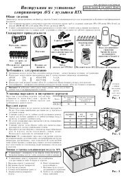
RGCAIR COOLED WATER CHILLERS <strong>AND</strong> HEAT PUMPSWITH CENTRIFUGAL FANS53.5 ÷ 200 kW IN COOLING MODE53.2 ÷ 202 kW IN HEATING MODEFERROLI adheres to theEUROVENT certificationprogramme.The products concernedappear in the productsguide to www.euroventcertification.com<strong>INSTALLATION</strong> <strong>AND</strong> <strong>OPERATION</strong> <strong>MANUAL</strong>
Dear Customer,Thank you for having purchased a FERROLI Idustrial coolers. It is the result of many years experience, particularresearch and has been made with top quality materials and higlly advanced technologies.The CE mark guaranteedthats the appliances meets European Machine Directive requirements regarding safety.The qualitative level is kept under constant surveillance. FERROLI products therefore offer SAFETY, QUALITY andRELIABILITY.Due to the continuous improvements in technologies and materials, the product specification as well as performancesare subject to variations without prior notice.Thank you once again for your preference.FERROLI S.p.AGB“CE” DECLARATION OF CONFORMITYWe, the undersigned, hereby declare under ourresponsibility, that the machine in question complieswith the provisions established by Directives :DK“CE” OVERENSSTEMMELSESERKLERINGUnderfegnede forsikrer under eget ansvar al denovennævnte maskine er i overensstemmelse medvilkårene i.direktiveme :DE“EG” KONFORMITÄTSERKLÄRUNGWir, die Unterzeichner dies er Erklärung, erklären unterunseren ausschlie ßlichen Verantworfung, daß diegenannte Maschine den Bestimmungen der folgendenEG-Richtlinien entspricht :SEFÖRSÄKRAN OM “CE” ÖVERENSSTÄMMELSEUnderfecknade försäkrar under eget ansvar altovannämnda maskinskinen er i overensstemmelsemed vilkarene i direktivene :FRDECLARATION “CE” DE CONFORMITENous soussignés déclarons, sous notre entièreresponsabilité, que la machine en objet est conformeaux prescriptions des Directives :NOBEKREFTELSE OM ÆCEØ OVERENSSTEMMELSEUnderfegnede forsikrer under eget ansvar al denovennevnte maskinen er i overensstemmelse medvilkarene i direktivene :ITDICHIARAZIONE “CE” DI CONFORMITÀNoi sottoscritti dichiariamo, sotto la nostra responsabilità,che la macchina in questione è conforme alleprescrizioni delle Direttive :FI“CE” VAATIMUSTENMUKAISUUSVAKUUTUSAllekirjoittaneet vakuutamme omalla vastuullammeettä yllämainittu kone noudattaa ehtoja direktiiveissä:ESDECLARACION “CE” DE CONFORMIDADQuienes subscribimos la presente declaracion,declaramos, baio nuestra exclusiva responsabilidad,que la maquina en objeto respeta lo prescrito par lasDirectivas :GRΔΗΛΩΣΗ ΣΥΜΒΑΤΟΤΗΤΑΣ “EE”Εμετς που υπογραϕουμε την παρουσα, δηλωνουμε υποτην αποκλειστικη μας ευθυνη, οτι το μηχανημασυμμορϕουται οτα οσ α ορτζουν οι Οδηγιες :PTDECLARAÇÃO “CE” DE CONFORMIDADENós, signatários da presente, declaramos sob anassa exclusiva responsabilidade, que a má quinaem questão está em conformidade com asprescrições das Directrizes :HRIZJAVA O “CE” SUGLASNOSTIMi niže potpisani izjavljujemo, pod našomodgovornošu, da ova Mašina odgovara zahtijevima izDirektiva :NL“EG” CONFORMITEITSVERKLARINGWij ondergetekenden verklaren hierbij op uitsluitendeigen verantwoording dat de bovengenoemde machineconform de voorschriften is van de Richtlijnen:PLDEKLARACJA ZGODNOŚCI “CE”My niżej podpisani oświadczamy z pełnąodpowiedzialnością, że niżej wymienione urządzenie wpełni odpowiada postanowieniom przyjętym wnastępujących Dyrektywach:2006/42/EC97/23/EC2004/108/EC2006/95/EC3QE22170 rev.032
TABLE OF CONTENTSTHIS <strong>MANUAL</strong> IS DIVIDED INTO SECTIONS. THEIR NAMES APPEAR IN THE HEADING OF EACH PAGE.GENERAL SPECIFICATIONS . . . . . . . . . . . . . . . . . . . . . . . . . .4GENERAL SPECIFICATIONS . . . . . . . . . . . . . . . . . . . . . . .4EUROPEAN DIRECTIVES . . . . . . . . . . . . . . . . . . . . . . . . . .4UNIT IDENTIFICATION PLATE . . . . . . . . . . . . . . . . . . . . . .4PRESENTATION OF THE UNIT . . . . . . . . . . . . . . . . . . . . . .5IDENTIFICATION CODE OF THE UNIT . . . . . . . . . . . . . . .5DESCRIPTION OF THE COMPONENTS . . . . . . . . . . . . . .6HYDRAULIC <strong>AND</strong> COOLING CIRCUIT COMPONENTS . . .8VERSION WITH DESUPERHEATER(AVAILABLE FOR BOTH IR UNITS <strong>AND</strong> IP UNITS) . . . . . .9ACCESSORIES <strong>AND</strong> OPTIONAL EQUIPMENT . . . . . . . . . . . .10MECHANICAL ACCESSORIES . . . . . . . . . . . . . . . . . . . . . .10ELECTRICAL ACCESSORIES . . . . . . . . . . . . . . . . . . . . . . .12MECHANICAL OPTIONS . . . . . . . . . . . . . . . . . . . . . . . . . . .12ELECTRICAL OPTIONS . . . . . . . . . . . . . . . . . . . . . . . . . . . .12ACCESSORIES - MODEL COMBINATIONS . . . . . . . . . . . .13TECHNICAL SPECIFICATIONS <strong>AND</strong> ST<strong>AND</strong>ARDPERFORMANCES - IR COOLING UNIT ONLY . . . . . . . . . . . . .15TECHNICAL SPECIFICATIONS OF UNIT AB ST<strong>AND</strong>ARDUNIT / AB ST<strong>AND</strong>ARD UNIT + KS SILENCER KIT . . . . . .15ST<strong>AND</strong>ARD PERFORMANCES AB ST<strong>AND</strong>ARD UNIT/ AB ST<strong>AND</strong>ARD UNIT + KS SILENCER KIT . . . . . . . . . . .16VERSION WITH DESUPERHEATER (VD) . . . . . . . . . . . . .18RECOVERED HEATING CAPACITYIN VERSION WITH DESUPERHEATER (VD) . . . . . . . . . .18SPECIFIC DATA FOT BRINE VERSION (VI) . . . . . . . . . . . .19TECHNICAL SPECIFICATIONS <strong>AND</strong> ST<strong>AND</strong>ARDPERFORMANCES - IP HEAT PUMP UNITS . . . . . . . . . . . . . . .20TECHNICAL SPECIFICATIONS OF UNIT AB ST<strong>AND</strong>ARDUNIT / AB ST<strong>AND</strong>ARD UNIT + KS SILENCER KIT . . . . . . .20ST<strong>AND</strong>ARD PERFORMANCES IN COOLING MODE AB . . . .ST<strong>AND</strong>ARD UNIT / AB ST<strong>AND</strong>ARD UNIT + KS SILENCER KIT .21ST<strong>AND</strong>ARD PERFORMANCES IN HEATING MODE ABST<strong>AND</strong>ARD UNIT / AB ST<strong>AND</strong>ARD UNIT + KS SILENCER KIT .23VERSION WITH DESUPERHEATER (VD) . . . . . . . . . . . . .24RECOVERED HEATING CAPACITYIN VERSION WITH DESUPERHEATER (VD) . . . . . . . . . .24NOISE LEVELS . . . . . . . . . . . . . . . . . . . . . . . . . . . . . . . . . . . . .25ST<strong>AND</strong>ARD AB VERSION . . . . . . . . . . . . . . . . . . . . . . . . . .25AB VERSION + LOW NOISE KIT KS . . . . . . . . . . . . . . . . . .25OPERATING RANG . . . . . . . . . . . . . . . . . . . . . . . . . . . . . . . . . .26OPERATING RANGE . . . . . . . . . . . . . . . . . . . . . . . . . . . . . .26WATER PRESSURE DROP PLATE HEAT EXCHANGER . . . .27WATER PRESSURE DROP OF THE DESUPERHEATER . . . .28WORKING HEAD OF THEPUMPING MODULE MP-AM <strong>AND</strong> MP-SS . . . . . . . . . . . . .29WORKING HEAD OF THEPUMPING MODULE MP-AM AP <strong>AND</strong> MP-SS AP . . . . . . .30MAXIMUM VOLUME OF WATER . . . . . . . . . . . . . . . . . . . . . . . .31MAXIMUM WATER VOLUME OF THE SYSTEMWITH HYDRONIC KIT . . . . . . . . . . . . . . . . . . . . . . . . . . . . .31VENTILATION UNIT CALIBRATION . . . . . . . . . . . . . . . . . . . . .32DIMENSIONAL DATA . . . . . . . . . . . . . . . . . . . . . . . . . . . . . . . . .33OVERALL DIMENSIONS . . . . . . . . . . . . . . . . . . . . . . . . . . .33DESCRIPTION OF THE COMPONENTS . . . . . . . . . . . . . .34POSITION OF CONDENSATE DRAIN . . . . . . . . . . . . . . . . .34MINIMUM OPERATIVE SPACE . . . . . . . . . . . . . . . . . . . . . .34CONFIGURATIONS FOR CHANNEL <strong>INSTALLATION</strong> . . . . .35WEIGHT DURING <strong>OPERATION</strong> <strong>AND</strong> TRANSPORT . . . . . . . .36VIBRATION-DAMPER <strong>INSTALLATION</strong> . . . . . . . . . . . . . . . .36AREA OF SUPPORT . . . . . . . . . . . . . . . . . . . . . . . . . . . . . .36WEIGHT DURING <strong>OPERATION</strong> <strong>AND</strong> TRANSPORT . . . . . .36MOD. 50 . . . . . . . . . . . . . . . . . . . . . . . . . . . . . . . . . . . . . . . .37MOD. 60 . . . . . . . . . . . . . . . . . . . . . . . . . . . . . . . . . . . . . . . .37MOD. 70 . . . . . . . . . . . . . . . . . . . . . . . . . . . . . . . . . . . . . . . .38MOD. 80 . . . . . . . . . . . . . . . . . . . . . . . . . . . . . . . . . . . . . . . .38MOD. 90 . . . . . . . . . . . . . . . . . . . . . . . . . . . . . . . . . . . . . . . .39MOD. 100 . . . . . . . . . . . . . . . . . . . . . . . . . . . . . . . . . . . . . . .39MOD. 115 . . . . . . . . . . . . . . . . . . . . . . . . . . . . . . . . . . . . . . .40MOD. 130 . . . . . . . . . . . . . . . . . . . . . . . . . . . . . . . . . . . . . . .40MOD. 145 . . . . . . . . . . . . . . . . . . . . . . . . . . . . . . . . . . . . . . .41MOD. 160 . . . . . . . . . . . . . . . . . . . . . . . . . . . . . . . . . . . . . . .41MOD. 180 . . . . . . . . . . . . . . . . . . . . . . . . . . . . . . . . . . . . . . .42MOD. 200 . . . . . . . . . . . . . . . . . . . . . . . . . . . . . . . . . . . . . . .42RECEPTION <strong>AND</strong> POSITIONING . . . . . . . . . . . . . . . . . . . . . . .43INSPECTIONS ON ARRIVA . . . . . . . . . . . . . . . . . . . . . . . . .43SAFETY PRESCRIPTIONS . . . . . . . . . . . . . . . . . . . . . . . . .43H<strong>AND</strong>LING . . . . . . . . . . . . . . . . . . . . . . . . . . . . . . . . . . . . . .43STORAGE . . . . . . . . . . . . . . . . . . . . . . . . . . . . . . . . . . . . . . .43ELECTRICAL CONNECTIONS . . . . . . . . . . . . . . . . . . . . . . . . .44GENERAL RULES . . . . . . . . . . . . . . . . . . . . . . . . . . . . . . . .44STRUCTURE OF THE ELECTRIC PANEL . . . . . . . . . . . . .44COMPOSITION OF THE SYSTEM . . . . . . . . . . . . . . . . . . .44ELECTRICAL CONNECTIONS . . . . . . . . . . . . . . . . . . . . . .44WET CONNECTIONS . . . . . . . . . . . . . . . . . . . . . . . . . . . . . . . . .47GENERAL RULES . . . . . . . . . . . . . . . . . . . . . . . . . . . . . . . .47HYDRAULIC LAYOUT OF THE SYSTEM . . . . . . . . . . . . . .47PRECAUTIONS FOR THE WINTER . . . . . . . . . . . . . . . . . .47BASIC DIAGRAM ST<strong>AND</strong>ARD UNIT VB[COLD WATER CIRCUIT] . . . . . . . . . . . . . . . . . . . . . . . . . . .48AIR VENT <strong>AND</strong> WATER DRAIN . . . . . . . . . . . . . . . . . . . . . .48PLUMBING CONNECTION WITH VICTAULIC COUPLINGS . .48BASIC DIAGRAM FOR UNITS WITH DESUPERHEATER[HOT WATER CIRCUIT] . . . . . . . . . . . . . . . . . . . . . . . . . . . .49VALVE REGULATING DIAGRAM VALVE . . . . . . . . . . . . . . . . . . . .49REFRIGERANT FLOW DIAGRAM BASIC VERSIONIN COOLING MODE IR . . . . . . . . . . . . . . . . . . . . . . . . . . . .51REFRIGERANT FLOW DIAGRAM BASIC VERSIONIN HEATING MODE IP . . . . . . . . . . . . . . . . . . . . . . . . . . . . . .52ADJUSTMENT <strong>AND</strong> CONTROL . . . . . . . . . . . . . . . . . . . . . . . .53CONTROL SYSTEM . . . . . . . . . . . . . . . . . . . . . . . . . . . . . . .53MENU STRUCTURE . . . . . . . . . . . . . . . . . . . . . . . . . . . . . .55INPUTS <strong>AND</strong> OUTPUTS . . . . . . . . . . . . . . . . . . . . . . . . . . .58CONTROLLER TECHNICAL DATA . . . . . . . . . . . . . . . . . . .59ALARMS . . . . . . . . . . . . . . . . . . . . . . . . . . . . . . . . . . . . . . . .60FUNCTIONS AVAILABLE FOR THE USER . . . . . . . . . . . . .62PROBE CHARACTERISTICS . . . . . . . . . . . . . . . . . . . . . . .64SERIAL COMMUNICATION . . . . . . . . . . . . . . . . . . . . . . . . .65SETTING AT WORK . . . . . . . . . . . . . . . . . . . . . . . . . . . . . . . . . .67GENERAL RULES . . . . . . . . . . . . . . . . . . . . . . . . . . . . . . . .67MAINTENACE . . . . . . . . . . . . . . . . . . . . . . . . . . . . . . . . . . . . . . .67MAINTENACE . . . . . . . . . . . . . . . . . . . . . . . . . . . . . . . . . . .67VENTILATING UNIT MAINTENANCE . . . . . . . . . . . . . . . . .68SAFETY <strong>AND</strong> PULLON . . . . . . . . . . . . . . . . . . . . . . . . . . . . . . .69GENERAL CONSIDERATIONS . . . . . . . . . . . . . . . . . . . . . .69REFRIGERANT SAFETY CARD . . . . . . . . . . . . . . . . . . . . .70FIRST AID . . . . . . . . . . . . . . . . . . . . . . . . . . . . . . . . . . . . . . .713
GENERAL SPECIFICATIONSGeneral specificationsThis manual and the wiring diagram supplied with the unit must be kept in a dry place for possible future consultation.The manual provides information on installation and correct use and maintenance of the unit. Before carrying out installation,please carefully read all the information contained in this manual, which describes the procedures necessary for correctinstallation and use of the unit.Carefully follow the instructions contained in this manual and comply with the current safety regulations. The unit must be installedin conformity with the laws in force in the country of use. Unauthorised tampering with the electrical and mechanical equipmentINVALIDATES THE WARRANTY.Check the electrical specifications given on the dataplate before making the electrical connections. Read the instructions givenin the specific section on electrical connections.Deactivate the equipment in case of a fault or poor operation.If the unit requires repairs, only contact a specialised service centre recognised by the manufacturer and use original replacementparts.The unit must be installed outside and connected to a hydronic cooling and/or heating system. Any use different from that permittedor outside the operating limits given in this manual is prohibited (unless previously agreed on with the firm).The manufacturer declines any liability for damage or injury due to non-compliance with the information given in this manual.European DirectivesThe company hereby declares that the machine in question complies with the matters prescribed by the following Directives:• Machinery directive 2006/42/EC• Pressurised equipment directive (PED) 97/23/EC• Electromagnetic compatibility directive (EMC) 2004/108/EC• Low voltage directive (LVD) 2006/95/ECUnit identification plateThe figure on the left illustrates the identification plate of the unit:Basic versionsA - TrademarkB- ModelC-Serial numberD-Cooling CapacityE-Heating CapacityF-Power input in COOLING modeG- Power input in HEATING modeH- Reference standardI - Electric power supplyL- Maximum current absorptionM- Type of refrigerant and weight of chargeN-Shipping weight of the unitO-Sound pressureP-IP Level ProtectionQ- Maximum pressure - High SideR- Maximum pressure - Low SideS- PED certification authoritySpecial versionsA - TrademarkB - ModelC - Serial numberD - Useful cooling output (same as Standard Version of the unit)E - Useful heating outputfor IR unit, VD version, same as the recovered Heat ratingfor IP unit, VD version, same as the Heat rating / recoveredHeat ratingF - Electric power draw in the COOLING mode (same asStandard version of the unit)G- Electric power draw in the HEATING modeH - Reference standardI - Electric power supplyL - Maximum electric current requirementM- Type of refrigerant and weight of chargeN - Shipping weight of the unitO - Acoustic pressureP - IP Protection degreeQ - Maximum pressure on top sideR - Maximum pressure on bottom sideS - PED certification authorityNOTE: The identification plate of the Brine Version (VI) is filledout as shown in the diagram for the Basic Version of theunit (VB).4
GENERAL SPECIFICATIONSPresentation of the unitThis new series of industrial chillers and heat pumps has been designed to meet the demands of globalmarkets in the small-medium power industrial and commercial plants. Units are compact and highlyconfigurable, built to fit different types of plants so to meet the needs of highly qualified engineers.Units are water chillers and heat pumps air condensed with centrifugal fans suitable for outdoor andindoor installation: the structure and panels are robust, made of galvanized and painted steel; all fastenersare made of stainless steel or galvanized steel, the frame containing the electrical equipment andall the components exposed to weather have a minimum IP54 degree of protection.This series is composed of 12 models divided in four sizes with nominal cooling capacity from 53.5 to200 kW and heating capacity from 53.2 to 202 kW.The units product cold water from 5 to 20°C (in summer) and hot water from 30 to 53°C (in winter) andthey can be equipped with continuous adjustment of centrifugal fans speed in order to allow the unitsto operate both with low outdoor temperature in cooling mode and with high outdoor temperature inheating mode as well as to reduce noise emissions (IMV accessory).All the units are equipped with 2 scroll compressors arranged in pairs (tandem) on 1 circuit operatingwith environmental friendly R410A gas, brazed plate heat exchanger completely insulated and protectedby water side with a differential pressure control and with an antifreeze electrical heater, coilheat exchanger made of louver aluminum fins and copper tubes, double inlet centrifugal fans with forwardcurved blades and transmission with belts and pulleys by a thermal protected motor, on-boardelectrical control panel equipped with control system to manage the main functions.Hydronic group (MP) composed of fittings and connections is available as an accessory with 1 or 2pumps and also with high available head pumps; the accessory Water Storage Tank (SAA) is completelyinsulated and available on delivery side or for primary-secondary hydraulic circuit (Victaulicconnections already in place) depending on the kind of plants to serve.A variety of other accessories are available to extend the capabilities of the units.During the design of the units particular attention has been given to achieve high system efficiency, toreduce overall energy consumptions and sound levels in order to meet the increasingly restrictive lawsin terms of noise. Upon request, you can choose for a Standard Unit (AB) or a Low Noise Kit (KS)which provides sound attenuation thanks to sound absorbing insulation in compressors area andsound jackets on compressors.All units are accurately build in compliance with the existing standards and are individually tested infactory. Only electrical and hydraulic connections are required for installation.Identification code of the unitThe codes that identify the units are listed below and include the sequences of letters that determinethe meanings for the various versions and set-ups.SeriesUnit typeIR- units suitable forhydronic plant installationoperating as chillers.IP- units suitable forhydronic plant installationoperating as heatpumps.RGC IP - 50.2 - VB - AB - 0 - M - 5Unit modelN° CompressorUnit versionVB - Standard unitVD- Desuperheater unitVI - Brine unitType of Refrigerant0 - R410AAcoustic VersionAB - Standard unitPower Supply5 - 400V - 3ph+N - 50HzOperating climateM - Medium temperature.Units are suitable to beinstalled in temperate climatesites.The available special versions are described below:VB: Basic version.VD: Version with Desuperheater (available forboth IR units and IP units)Produces cold water in the same way as the standard version plus hot water from 40 to 70°C at the same time. Thisis achieved by installing a water-refrigerant gas heat exchanger between the compressor and coils in order to recover15 to 20% of the heating capacity that would otherwise be dispersed in the air.VI: Version that produces water at a low temperature (BRINE) (available for IR units only)The unit can produce cold water with brine at a temperature of -8 to 5°C.5
GENERAL SPECIFICATIONSDescription of the componentsThe complete series of industrial chillers and heat pumps for use in hydronic systems includes 12 constructional sizes rangfrom 53.5 to 200 kW in the cooling mode and from 53.2 to 202 kW in the heating mode.Main components:1. Fans. It is composed of single and/or twin dual-intake centrifugal fans with forwards blades curved, balanced both staticallyand dynamically in compliance with ISO 1940 class 6.3 standards. The screw conveyor, rotor and frame are made of galvanizedplate, while the shaft is made of C40 steel. The fan is coupled via belt and pulley to a 4-pole, three-phase, asynchronousmotor secured on a special tightener slide, with protection class IP55, insulation class F and suitable for continuous service(S1) with sufficient thermal margin in the event of overloads of limited duration. The pulley fitted on the motor has a variablediameter and, within certain limits, enables adjusting the speed of rotation of the fan in order to obtain the desired air flowrate and useful static head.2. Electric control and monitoring panel. This is housed in a metal casing in which the various electrical components are positionedon one metal plate.2a. The power section includes:• Main door-locking circuit-breaker.• Fuse-holder that can be isolated with protection fuse triad for each compressor.• Fuse-holder that can be isolated with protection fuse for compressor oil heaters and antifreeze (if installed).• Control contactor for each compressor.• Protection fuse for the ventilation unit.• Fan speed regulating board.• Contactor and magnetothermic switch to protect the pump (if the Hydronic Kit accessory is installed).• Pump contactor (if the Hydronic Kit accessory is installed).• Phase presence and sequence monitoring device on power supply2b. The auxiliary section includes:• Fuses on the auxiliary transformer.• Fuses for fans protection• Electromagnetic noise filterMODE• Adjusting fan speed board• Insulating and safety transformer to power the auxiliary circuit.2c. The microprocessor monitoring section includes:°C• User interfacing terminal with display.• On-off key.• Operating mode selector key.• Compressor on-off display LED.• Operational mode LED• Antifreeze heaters activated indicator LED.• Fans on-off dislay LED• Pumps on-off display LED• Check-control with fault code display• Defrosting, alarm, economy, stand-by LED.• Remote ON/OFF functions - Summer/Winter (E/I) remote selection (IP unit only).Control system main functions: temperature control of the water produced by the unit, smart defrosting control, compressorand pump operating hour counter, timing and cycling of start-ups, input parameters by keyboard, alarms management, operatingmode change (only IP unit), dynamic set-point (climatic control), “Adaptive” function for better temperature control for unit withoutstorage tank.Digital input functions: low pressure, high pressure, high temperature on compressor supply, phase presence and sequencemonitoring device on power supply, differential water pressure control, compressors thermal protection, fans thermal protection,pumps thermal protection (only if installed MP accessory), remote ON/OFF and remote operating mode change (only IP unit).Digital output functions: compressor start-up, pump start-up (only with MP accessory), plate heat exchanger electrical heater,remote general alarm, 4-way valve (only IP unit).Analogic input functions: in and out water temperature, coil temperature probe, external air temperature probe (if present).Analogic output functions: continuous adjustment of centrifugal fans rotating speed by inverter (only if installed IMV accessory).6
GENERAL SPECIFICATIONS71625433. Compressors. They are the SCROLL type with orbiting coil equipped with built-in thermal protection and oil heater. The KSkit includes: a soundproofing jacket for the compressors and acoustic cladding for the entire compressor compartment to reducethe noise level. All units are equipped with two compressors connected in parallel (1 single cooling circuit) which can operateat the same time (100% cooling power) or individually (50% of the cooling power), thus adapting to the different thermalloads of the system supplied.4. Frame structure made of galvanized sheet metal panels coated with polyurethane powder paint to ensure maximun protectionagainst adverse weather conditions.5. Evaporator made of brazed stainless steel plates (AISI 316). It is installed in a shell of heat-insulating material to preventthe formation of condensation and heat exchanges towards the outside. Standard supply also includes antifreeze heater a differentialpressure switch on the water circuit to avoid the risk of freezing if the water flow is shut off for some reason.6. Condensing coils, the aluminium finned pack type with shaped profile to increase the heat exchange coefficient and withcopper pipes arranged in staggered rows. A sub-cooling section is integrated into the lower part.7. Covering panels, made of galvanized sheet metal coated with polyurethane powder paint to ensure maximun protectionagainst adverse weather conditions8.One-way valves (IP unit only), allowing the coolant to pass into the appropriate exchangers, depending on the operatingcycle.4-way cycle reversal valve (IP unit only), reverses the flow direction of the coolant as the summer/winter operating mode ischanged.7
GENERAL SPECIFICATIONSHydraulic and cooling circuit components10. Drain Pan Kit (standard for IP version). Provides a pan under the coil to drain the condensing water, fitted with 1/2" outletconnection positioned opposite the electric control panel.11. Fluid cock. Ball type, this allows the gas flow on the fluid line to be turned on and off. Along with the cock on the compressordelivery, it allows the components of the fluid line to be subjected to extraordinary maintenance work and the compressorsto be replaced if necessary (without discharging the coolant from the unit).12. Compressor delivery cock. Ball type, allows the gas delivered to the compressors to be turned on and off.13. Dehydrator filter. Mechanical type. Retains impurities and traces of moisture in the circuit. Hermetic type for models 50÷80;cartridge type for models 90÷160.14. Fluid and humidity indicator. Signals when fluid passes through the circuit, indicating that the coolant charge is correct.The fluid indicator light also indicates the amount of moisture in the coolant by changing colour.15. Low pressure switch (N°1 of series IR version, N°2 of series IP version). With fixed setting. It is installed on the suctionpipe and blocks the compressors if the operating pressures drop below the tolerated values. Automatically resets as the pressureincreases. If it activates frequently, the unit will block and can only be restarted by resetting via the user interface terminal.16. High pressure switch (n°2). With fixed setting. Are is installed on the delivery pipe and blocks the compressors if the operatingpressures exceed the tolerated values. If it activates, the unit will block and can only be restarted by resetting via the userinterface terminal.17. Thermostatic valve. With external equalizer, this supplies the evaporator correctly, keeping the selected overheating degreeat a steady level.18. Water differential pressure switch. This is standard supply and is installed on the connections between the water inlet andoutlet of the exchanger. It stops the unit if it activates.19. Pressure taps: 1/4 " SAE (7/16" UNF) type with flow regulator. Allow the operating pressure of the system to be measured:compressor delivery, lamination component inlet, compressor intake.20. Pressure taps: 5/16 " SAE type with flow regulator. Allow the charge/discharge of the gas from the system, precisely fromcompressor outlet an expansion valve inlet.21. Electrical heating elements to heat the compressor oil. "Belt" type. These activate when the compressor turns off andkeep the temperature of the oil sufficiently high so as to prevent coolant from migrating during these pauses.Safety valve. Installed on the delivery pipe of the compressors, this operates if extreme faults should occur in the plant.Fluid receiver (IP unit only), this is a plenum tank that accounts for variations to the coolant charge the machine must supplyas the summer/winter operating mode varies.Fluid separator (IP unit only), on the compressor intake to protect against possible fluid back-flows.12118151820171916211310148
GENERAL SPECIFICATIONSVersion with Desuperheater VD (available for both IR units and IP units)Hydraulic and chilling circuit components:1. Desuperheater. Specially designed for the specific version. Plate type, made of stainless steel (AISI 316).It is installed within a shell of thermal barrier insulating material to prevent heat exchanges towards the outside. Standard supplyalso includes an electric antifreeze heater to prevent the parts from freezing during the winter, when the system remains at a standstill(if not drained).2. Water safety valve.On the heat recovery inlet pipe. It acts whenever faulty service leads to an operating pressure in the plumbingsystem that exceeds the valve opening value (Fig.1).3. Water drain cock for emptying the exchangers and pipes of the machine dedicated to heat recovery (Fig. 1).4. Air vent. Accessed by removing the front panels. It consists of a manually operated valve installed in the highest part of thewater pipes. To use in conjunction with the water drain cocks situated in the rear part of the unit, for emptying the exchangersand pipes dedicated to heat recovery.24319
ACCESSORIES <strong>AND</strong> OPTIONAL EQUIPMENTMechanical optionsAVG - Rubber vibration dampers. Consisting of 4/6 rubber vibration dampers to fit under the unit. Reduce the extent to whichthe mechanical vibrations created by the compressors and fans during normal operation are transmitted to the bearing surfaceof the machine. The insulating degree of the vibration dampers is about 85%.GM - Pressure gauge unit. Consisting of 2 pressure gauges that display the pressure values of the refrigerating fluid on thecompressor suction and delivery sides.GP - Protective grilles. These are metal grilles installed to protect the finned banks.SAA - Water storage tank. Made of adequately thick painted sheet metal, this reduces the number of compressor start-ups and fluctuations inthe temperature of the water conveyed to the users. It is insulated with thermal barrier material to prevent the formation of condensation and heatexchanges towards the outside.Water storage tank. It consists of:Water draining. On-off action by means of a cock that can be accessed by removing the rear panel, positioned on the side of the unit oppositeto the electric panel.Air vent. Accessed by removing the rear panel positioned on the side of the unit opposite to the electric panel. It consists of a manually operatedvalve installed on the highest part of the wet pipes.Water safety valve, on the rear part of the tank. It acts whenever faulty service leads to an operating pressure in the hydraulic circuit thatexceeds the valve opening value.Antifreeze heater connection. 1”1/4 female threaded connection pre-engineered for installation of the antifreeze heater (RAG accessory).KS- Low noise kit (M). Provides sound attenuation thanks to sound absorbing insulation in compressors area and sound jackets on compressors.KB- KB- Drain Pan Kit (standard for IP version) (M). Provides a pan under the coil to drain the condensing water, fitted with 1/2" outlet connectionpositioned opposite the electric control panel.KT - the following kits are available (this accessory is mandatory if the Hydronic Kit is not installed).- Basic pipe kit. This accessory consists of steel pipes insulated with thermal barrier material and allows the water inlet/outlet to be connectedstraight inside the unit.- Complete pipe kit. This accessory consists of steel pipes insulated with thermal barrier material and allows the water inlet/outlet connectionto be routed to the machine.- Water storage tank pipe kit. This accessory consists of steel pipes insulated with thermal barrier material and allows the water inlet/outletconnection to be routed to the machine.NB: YOU CAN CHOOSE ONLY ONE KIT.• MP. Hydronic Kit (M). Consists of:1 On-off ball valves. Turn components such as the water filter, surge chamber and pump on and off when they require routine or extraordinarymaintenance.2 Metal gauze water filter. Can be turned on and off and inspected. It is installed on the pump delivery side. Prevents machining residues(dust, swarf, etc.) in the water pipes from entering the plate-type heat exchanger.3 Hydraulic pump. Circulates water around the system. The pumps have a low/high head and suit the majority of installation requirements.The pumps are safeguarded by a magnetothermics installed in the chiller’s electric panel.4 Surge chamber. This is a closed, diaphragm type chamber. It absorbs the variations in the volumes of water in the system caused by temperaturevariations.5 Water filling. Manual function with control positioned on the side of the unit opposite the electric panel and turned on and off by a cock thatcan be accessed by removing the rear panel.6 Water pressure gauge. Connected to the water fill pipe. Displays the pressure of the water in the system.7 Water safety valve.8 Water outlet.9 Air vent.10 Antifreeze heater connection (RAG accessory).MP. Hydronic Kit.MP : Hydronic Kit with 1 o 2 Pumps: Besides the pumps, this accessory is equipped with all the hydraulic components (water filter, expansiontank, on-off valves, water pressure gauge, air vent, water outlet) required for complete installation and easy maintenance.Different water accumulation tank configurations are therefore available in combination with the Hydronic Kit accessory:MP - AM: Accumulation on the Plant Delivery side (Standard) (A) : The pump draws water from the system, sends it to the plate exchangerand from thence to the inertial accumulation tank. During normal operating conditions, the pump in this configuration is able to providea residue head from 86 to 150 kPa (from 9 to 15 m.w.c.) for the circulating water.MP - AM AP: Accumulation on the Plant Delivery side (High) (B) .: The pump draws water from the system, sends it to the plate exchangerand from thence to the inertial accumulation tank. During normal operating conditions, the pump in this configuration is able to providea residue head from 198 to 255 kPa (from 20 to 25 m.w.c.) for the circulating water.MP - PS: Accumulation pre-engineered for the primary and secondary circuit : The sole function of the pump is to circulate the wateraround the primary circuit: this circuit includes the accumulation tank and plate exchanger (chiller water circuit). The installer must mount thepumping section relative to the secondary circuit formed by the accumulation tank (with the pre-engineered wet connections) and the systemserved. No high working head version available.MP-SS: Hydronic Kit without Water Storage Tank (Standard) (A) . The pump draws water from the system, sends it to the plate heatexchanger and returns it to the system. During normal operating conditions, the pump in this configurations can provide a residue head from86 to 150 kPa (from 9 to 15 m w.c.).MP-SS AP: Hydronic Kit without Water Storage Tank (High Working Head) (B) . The pump draws water from the system, sends it to theplate heat exchanger and returns it to the system. During normal operating conditions, the pump in this configurations can provide a residuehead from 198 to 255 kPa (from 20 to 25 m w.c.).(A): For the working head values depending on the water flow rate, consult the Standard Working Head MP-AM graph.(B): For the working head values depending on the water flow rate, consult the High Working Head MP-AM graph.NOTE: (M): Installed (F): To be installed by customersNOTE: It is essential to purchase the units with either the KT or MP accessory described previously.The choice of one automatically excludes the other.10
ACCESSORIES <strong>AND</strong> OPTIONAL EQUIPMENTKT - BASIC PIPE KIT KT - COMPLETE PIPE KIT WATER STORAGE TANK PIPE KITMP - 1P AMMP - 1P AM APMP - 1P PSMP - 2P AMMP - 2P AM APMP - 2P PSMP - 1P SSMP - 1P SS APMP - 2P SSMP - 2P SS AP11
ACCESSORIES <strong>AND</strong> OPTIONAL EQUIPMENTElectrical optionsCR - Remote control (F). This can be used to select all the monitoring and display functions of the control unit onthe machine at a maximum distance of 100 meters away. It must be installed by using a cable with three strandsor three wires in PVC of the N07-VK type with a 1mm 2 section. The transmission line must be installed in a racewayseparate from any electric powering wires (230/400 V).The control unit has the following buttons:MODE key : used to select the operating modeMODEON/OFF key : used to turn the unit ON/OFF and to reset the alarms°CMode + ON/OFF keys : used to access and quit the various menu levelsUP key: scrolls forwards through the menu items or increases the value of a parameterTasto DOWN: scrolls backwards through the menu items or decreases the value of a parameter.KOP - Programmer clock (F). Allows the unit to be turned on and off depending on the programmed time setting (up to 14switching actions can be programmed as required throughout the 7 days of the week).RAG: Antifreeze heating element for the accumulation tank (M/F). Plug type. This activates in parallel with the evaporator’santifreeze heating element and keeps the water at a temperature able to prevent ice from forming when the unit remains idleduring the winter.TAT- High Temperature Thermostat (M). Two thermostats in series on compressors outlet pipes preserve operation not allowingtemperature to rise up than a specified non adjustable value.SND- External Air Probe (M). External air probe mounted near coil allows smart defrosting and climatic variation of setpointINT - Serial interface (F). Allows serial communication on RS485 by MODBUS protocolIMV- Fan motor inverter(M). Adjusts continuously centrifugal fan speed in order to allow the units to operate both with lowoutdoor temperature in cooling mode and with high outdoor temperature in heating modeNOTE: (M): Factory mounted(F): To be installed by customersMechanical optionsSpecial finned heat exchangers• Coils with copper fins• Coils with tin-coated copper fins• Coils with aluminium fins with acrylic coatingElectrical optionsOther power source voltage rating (contact our technical department).12
ACCESSORIES <strong>AND</strong> OPTIONAL EQUIPMENTAccessories - Model CombinationsMechanical AccessoriesMODEL / ACCESSORY CODE M / F 50 60 70 80 90 100 115 130 145 160 180 200With TankAVG13 F • • • •AVG15 F • • • • • • • •Rubber vibrationdampersAVG12 F • • • •Without Tank AVG14 F • • • • • •AVG16 F • •Gas pressure gauges GM12 M • • • • • • • • • • • •GP49 M • • • •Protective grillesGP50 M • •GP51 M • • • •GP66 M • •BCN3 M • • • •Drain pan kit (1)BCN4 M • • • • • •BCN12 M • •KS5 M • • • •KS6 M •Low noise kitKS7 M •KS8 M •KS9 M • • •KS15 M • •Basic pipe kitKT30 M • • • •KT29 M • • • • • • • •KT31 M • • • •Copmplete pipe kitKT33 M • • • • • •KT40 M • •KT34 M • • • •Tank pipe kitKT35 M • • • • • •KT41 M • •SAA29 M • • • •Water storage tankSAA30 M • • • • • •SAA39 M • •NOTE:(M): factory mounted(F): to be installed by customer(1): standard for IP versionTable Continued on next page.13
ACCESSORIES <strong>AND</strong> OPTIONAL EQUIPMENTMechanical AccessoriesElectrical AccessoriesHydronic kitMODEL / ACCESSORY CODE M / F 50 60 70 80 90 100 115 130 145 160 180 200MP105 M • • • •1 PumpMP106 M • • • •MP113 M • •With tank on delivery(StandardMP147 M • •Head)MP122 M • • • •2 PumpsMP124 M • • • •MP133 M • •MP152 M • •MP107 M • • • •1 PumpMP108 M • •MP109 M • • • •With tank on deliveryMP148 M • •(High Head)MP125 M • • • •2 PumpsMP126 M • •MP127 M • • • •MP153 M • •MP111 M • • • •1 PumpMP112 M • • • •MP113 M • •With tank for primary- SecondaryMP149 M • •circuitMP128 M • • • •2 PumpsMP129 M • • • •MP130 M • •MP154 M • •MP117 M • • • •1 PumpMP118 M • • • •MP131 M • •Without tankMP150 M • •(Standard Head)MP134 M • • • •2 PumpsMP135 M • • • •MP136 M • •MP155 M • •MP119 M • • • •1 Pump1 MP120 M • •Pump MP121 M • • • •Without tank (HighMP151 M • •Head)MP137 M • • • •2 PumpsMP138 M • •MP139 M • • • •MP156 M • •MODEL / ACCESSORY CODE M / F 50 60 70 80 90 100 115 130 145 160 180 200External air probe SND3 M • • • • • • • • • • • •Programming clock kit KOP1 F • • • • • • • • • • • •Storage tank electrical heater kitRAG13 M • • • • • • • • • • • •RAG14 F • • • • • • • • • • • •High temperature thermostat kit (2) TAT8 M • • • • • • • • • • • •Remote control kit CR6 F • • • • • • • • • • • •Serial interface kit INT2 M • • • • • • • • • • • •VRT5 M • • • •Kit InverterVRT6 M • •VRT7 M • •VRT8 M • • • •NOTE:(M): factory mounted(F): to be installed by customer(2): standard for VI version14
TECHNICAL SPECIFICATIONS <strong>AND</strong> ST<strong>AND</strong>ARD PERFORMANCES - IR COOLING UNIT ONLYTechnical specifications of unit AB Standard Unit / AB Standard Unit + KS Silencer kitModel 50 60 70 80 90 100 115 130 145 160 180 200 UMPower supply 400V - 3ph+N - 50 Hz V-f-HzType of refrigerant R410A /Circuits 1 n°Cooling capacity (1) (E) 53,5 58,6 68,8 78,7 91,0 102 112 126 143 158 180 200 kWCompressors power input (1) 16,3 18,5 20,9 25,6 28,2 31,6 35,5 40,5 46,0 51,0 56,0 62,8 kWEER 3,28 3,17 3,29 3,07 3,23 3,22 3,15 3,11 3,11 3,10 3,21 3,18 -Total power input (1) 21,8 24,0 26,4 31,1 34,4 37,8 44,5 49,5 62,5 67,5 78,0 84,8 kWTotal power input (1) (E) 17,8 20,0 22,5 27,3 30,6 34,1 37,9 42,9 53,9 59,2 66,5 73,7 kWTotal EER 3,01 2,93 3,06 2,88 2,97 2,98 2,96 2,94 2,65 2,67 2,71 2,71 -ESEER (E) 4,15 4,04 4,22 3,98 4,10 4,11 4,08 4,05 3,66 3,68 3,74 3,74 -Water flow rate (1) 2,56 2,80 3,29 3,76 4,35 4,85 5,35 6,02 6,83 7,55 8,60 9,56 l/sWater pressure drops (1) (E) 42 51 48 40 40 40 40 39 39 39 58 57 kPaWorking head (1) (MP) 135 116 97 75 143 129 113 92 116 95 141 107 kPaCompressorType Scroll /Quantity 2 n°Load steps 0-50-100 %Oil charge CP1 3,25 3,25 3,25 3,25 3,25 4,7 4,7 6,8 6,8 6,3 6,3 6,3 lOil charge CP2 3,25 3,25 3,25 3,25 4,7 4,7 6,8 6,8 6,3 6,3 6,3 6,3 lHeat ExchangerType Brazed plates /Quantity 1 n°Water volume 3,6 3,6 4,6 5,4 7,6 8,4 9,7 10,9 12,6 14,5 11,1 13,0 lFanType Centrifugal -Quantity 1 2 3 4 n°Total air flow rate 29050 29050 28100 27680 41460 40100 47440 47440 62190 59820 82920 79760 m 3 /hWorking head NOM/MAX (3) 50 /150 rpmPower input 5,5 6,2 9 16,5 22 kWCoilType Aluminum fins and copper tubes /Quantity 1 n°Front area 3,38 4,72 5,90 7,41 m 2Water Storage Tank (SAA accessory)Water volume 200 400 460 lSafety valve setting 600 kPaSurge chamber volume 12 24 lSurge chamber default pressure 150 kPaMax. operating pressure 1000 800 kPaElectrical DataUnits without pumping moduleTotal maximum power input [ FLA ] 52,7 55,3 62,8 73,1 80,6 86,1 101 109 138 152 178 193 ATotal maximum power input [ FLI ] 30,3 32,5 35,9 40,3 47,1 52,7 60,9 65,6 82,7 91,5 108 119 kWTotal maximum starting current [ MIC ] 150 151 177 215 269 275 328 336 389 403 498 513 AUnits with pumping module MP-AM and MP-PS (1 or 2 pumps)Total maximum power input [ FLA ] 55,9 58,5 66,0 76,3 85,4 90,9 106 114 144 158 186 201 ATotal maximum power input [ FLI ] 32,1 34,3 37,7 42,1 50,0 55,6 63,8 68,5 85,9 94,7 113 124 kWTotal maximum starting current [ MIC ] 153 155 180 218 274 279 333 341 394 409 507 521 AUnits with pumping module MP-AM AP (1 or 2 pumps)Total maximum power input [ FLA ] 58,9 61,6 69,0 79,3 86,8 92,4 109 117 146 161 189 204 ATotal maximum power input [ FLI ] 34,1 36,3 39,7 44,1 50,8 56,5 65,6 70,3 87,5 96,3 115 126 kWTotal maximum starting current [ MIC ] 156 158 183 221 275 281 336 345 397 411 509 524 AData referred to standard operating condition.(1): water temperature: in 12°C - out 7°C air temperature: in 35°C d.b.(2): water temperature: in 40°C - out 45°C air temperature: in 7°C d.b. 87% RH(3): Adjustable changing the diameter of the motors pulley(MP): with standard hydronic kit MP-AM and MP-SS(SAA): with storage tank(E): data declared according to LCP EUROVENT certification program, Total power input is corrected of external available static pressure as defined in UNI EN14511:200815
TECHNICAL SPECIFICATIONS <strong>AND</strong> ST<strong>AND</strong>ARD PERFORMANCES - IR COOLING UNIT ONLYStandard performances AB Standard unit / AB Standard Unit + KS Silencer kitMod. 50-100MOD.5060708090100TwOUTDOOR AIR TEMPERATURE (°C D.B.)20 25 30 35 40 45 50kWf kWa kWf kWa kWf kWa kWf kWa kWf kWa kWf kWa kWf kWa5 61,1 11,4 57,0 13,2 53,9 14,5 50,6 16,0 47,1 17,6 43,6 19,2 40,0 20,86 62,8 11,5 58,6 13,3 55,4 14,6 52,0 16,1 48,4 17,8 44,8 19,4 41,1 21,07 64,6 11,7 60,3 13,4 57,0 14,8 53,5 16,3 49,8 18,0 46,1 19,6 42,3 21,28 66,4 11,8 62,0 13,6 58,6 14,9 55,0 16,5 51,2 18,2 47,4 19,8 - -9 68,2 11,9 63,7 13,7 60,2 15,1 56,5 16,6 52,6 18,3 48,7 20,0 - -10 70,1 12,0 65,4 13,8 61,8 15,2 58,0 16,8 54,0 18,5 50,0 20,2 - -11 71,8 12,1 67,1 14,0 63,4 15,4 59,5 17,0 55,4 18,7 51,3 20,4 - -12 73,8 12,3 68,9 14,1 65,1 15,5 61,1 17,1 56,9 18,9 52,7 20,6 - -5 66,9 13,0 62,4 14,9 59,0 16,5 55,4 18,1 51,5 20,0 47,7 21,8 43,9 23,66 68,7 13,1 64,2 15,1 60,7 16,6 56,9 18,3 53,0 20,2 49,1 22,0 45,1 23,87 70,7 13,2 66,0 15,2 62,4 16,8 58,6 18,5 54,5 20,4 50,5 22,2 46,4 24,08 72,8 13,4 67,9 15,4 64,2 17,0 60,3 18,7 56,1 20,6 51,9 22,5 - -9 74,8 13,5 69,8 15,6 66,0 17,1 61,9 18,9 57,6 20,8 53,4 22,7 - -10 76,7 13,7 71,6 15,7 67,7 17,3 63,6 19,1 59,1 21,0 54,8 22,9 - -11 78,7 13,8 73,5 15,9 69,5 17,5 65,2 19,3 60,7 21,2 56,2 23,2 - -12 80,8 13,9 75,5 16,0 71,3 17,6 67,0 19,5 62,3 21,4 57,7 23,4 - -5 78,5 14,7 73,3 16,9 69,3 18,6 65,0 20,5 60,5 22,6 56,1 24,6 51,5 26,66 80,7 14,8 75,3 17,0 71,2 18,8 66,9 20,7 62,2 22,8 57,6 24,9 52,9 26,97 83,1 15,0 77,5 17,2 73,3 19,0 68,8 20,9 64,0 23,0 59,3 25,1 54,5 27,28 85,4 15,1 79,7 17,4 75,4 19,2 70,7 21,1 65,8 23,3 61,0 25,4 - -9 87,8 15,3 81,9 17,6 77,5 19,4 72,7 21,3 67,6 23,5 62,6 25,6 - -10 90,1 15,4 84,1 17,7 79,5 19,5 74,6 21,6 69,4 23,8 64,3 25,9 - -11 92,4 15,6 86,2 17,9 81,6 19,7 76,5 21,8 71,2 24,0 66,0 26,2 - -12 94,9 15,7 88,6 18,1 83,8 19,9 78,6 22,0 73,1 24,2 67,7 26,4 - -5 89,8 18,0 83,9 20,7 79,3 22,8 74,4 25,1 69,2 27,7 64,1 30,2 58,9 32,66 92,3 18,1 86,2 20,9 81,5 23,0 76,5 25,3 71,1 27,9 65,9 30,5 60,5 32,97 95,0 18,3 88,7 21,1 83,9 23,2 78,7 25,6 73,2 28,2 67,8 30,8 62,3 33,38 97,7 18,5 91,2 21,3 86,2 23,5 80,9 25,9 75,3 28,5 69,7 31,1 - -9 100 18,7 93,7 21,5 88,6 23,7 83,2 26,1 77,4 28,8 71,7 31,4 - -10 103 18,9 96,2 21,7 91,0 23,9 85,4 26,4 79,4 29,1 73,6 31,7 - -11 106 19,1 98,7 21,9 93,3 24,2 87,5 26,7 81,5 29,4 75,4 32,0 - -12 109 19,3 101 22,2 95,8 24,4 89,9 26,9 83,7 29,7 77,5 32,3 - -5 104 19,8 97,0 22,8 91,7 25,1 86,0 27,7 80,1 30,5 74,1 33,2 68,1 35,96 107 20,0 100 23,0 94,2 25,3 88,4 27,9 82,3 30,8 76,2 33,5 70,0 36,37 110 20,2 103 23,2 97,0 25,6 91,0 28,2 84,7 31,1 78,4 33,9 72,0 36,68 113 20,4 105 23,5 100 25,9 93,6 28,5 87,1 31,4 80,6 34,3 - -9 116 20,6 108 23,7 102 26,1 96,2 28,8 89,5 31,7 82,9 34,6 - -10 119 20,8 111 23,9 105 26,4 98,7 29,1 91,8 32,1 85,1 34,9 - -11 122 21,0 114 24,2 108 26,6 101 29,4 94,2 32,4 87,2 35,3 - -12 126 21,2 117 24,4 111 26,9 104 29,7 96,7 32,7 89,6 35,6 - -5 116 22,2 109 25,5 103 28,1 96,4 31,0 89,7 34,2 83,1 37,2 76,3 40,36 120 22,4 112 25,7 106 28,4 99,1 31,3 92,2 34,5 85,4 37,6 78,4 40,67 123 22,6 115 26,0 109 28,7 102 31,6 94,9 34,8 87,9 38,0 80,7 41,18 127 22,9 118 26,3 112 29,0 105 31,9 97,6 35,2 90,4 38,4 - -9 130 23,1 121 26,6 115 29,3 108 32,3 100 35,6 92,9 38,8 - -10 134 23,3 125 26,8 118 29,6 111 32,6 103 35,9 95,3 39,2 - -11 137 23,5 128 27,1 121 29,8 113 32,9 106 36,3 97,8 39,5 - -12 141 23,8 131 27,4 124 30,1 117 33,2 108 36,6 100 39,9 - -Tw= Outlet water temperature °C kWf = refrigerating power (kW). kWa = Power input of compressors (kW)The standard performances refer to a 5°C temperature difference between the water entering and leaving the plate-type heat exchanger and to operation of the unitwith all fans at top speed. A 0.44 x 10 -4 m 2 K/W fouling factor has also been considered with the unit installed at zero meters above sea level (Pb = 1013mbar).16
TECHNICAL SPECIFICATIONS <strong>AND</strong> ST<strong>AND</strong>ARD PERFORMANCES - IR COOLING UNIT ONLYMod. 115-200MOD.115130145160180200TwOUTDOOR AIR TEMPERATURE (°C D.B.)20 25 30 35 40 45 50kWf kWa kWf kWa kWf kWa kWf kWa kWf kWa kWf kWa kWf kWa5 128 24,9 119 28,7 113 31,6 106 34,8 98,5 38,4 91,3 41,8 83,8 45,26 131 25,1 123 28,9 116 31,9 109 35,1 101 38,7 93,8 42,2 86,1 45,77 135 25,4 126 29,2 119 32,2 112 35,5 104 39,1 96,5 42,7 88,6 46,18 139 25,7 130 29,5 123 32,6 115 35,9 107 39,6 99,2 43,1 - -9 143 25,9 133 29,8 126 32,9 118 36,3 110 40,0 102 43,6 - -10 147 26,2 137 30,1 129 33,2 121 36,6 113 40,4 105 44,0 - -11 150 26,5 140 30,4 133 33,5 125 37,0 116 40,7 107 44,4 - -12 154 26,7 144 30,7 136 33,9 128 37,3 119 41,1 110 44,9 - -5 144 28,4 134 32,7 127 36,0 119 39,7 111 43,8 103 47,7 94,3 51,66 148 28,7 138 33,0 130 36,4 122 40,1 114 44,2 106 48,2 96,9 52,17 152 29,0 142 33,3 134 36,7 126 40,5 117 44,6 109 48,7 100 52,68 156 29,3 146 33,7 138 37,1 130 40,9 121 45,1 112 49,2 - -9 161 29,6 150 34,0 142 37,5 133 41,4 124 45,6 115 49,7 - -10 165 29,9 154 34,4 146 37,9 137 41,8 127 46,0 118 50,2 - -11 169 30,2 158 34,7 149 38,3 140 42,2 130 46,5 121 50,7 - -12 174 30,5 162 35,1 153 38,6 144 42,6 134 46,9 124 51,2 - -5 163 32,3 152 37,1 144 40,9 135 45,1 126 49,7 117 54,2 107 58,66 168 32,6 157 37,5 148 41,3 139 45,5 129 50,2 120 54,7 110 59,27 173 32,9 161 37,9 152 41,7 143 46,0 133 50,7 123 55,3 113 59,88 178 33,3 166 38,3 157 42,2 147 46,5 137 51,3 127 55,9 - -9 182 33,6 170 38,7 161 42,6 151 47,0 141 51,8 130 56,4 - -10 187 33,9 175 39,1 165 43,0 155 47,4 144 52,3 134 57,0 - -11 192 34,3 179 39,4 170 43,5 159 47,9 148 52,8 137 57,6 - -12 197 34,6 184 39,8 174 43,9 163 48,4 152 53,3 141 58,1 - -5 180 35,8 168 41,2 159 45,4 149 50,0 139 55,1 129 60,1 118 65,06 185 36,1 173 41,6 164 45,8 154 50,5 143 55,6 132 60,7 122 65,67 191 36,5 178 42,0 168 46,3 158 51,0 147 56,2 136 61,3 125 66,38 196 36,9 183 42,4 173 46,8 162 51,6 151 56,8 140 62,0 - -9 202 37,3 188 42,9 178 47,2 167 52,1 155 57,4 144 62,6 - -10 207 37,6 193 43,3 183 47,7 171 52,6 159 58,0 148 63,2 - -11 212 38,0 198 43,7 187 48,2 176 53,1 164 58,5 151 63,8 - -12 218 38,4 203 44,1 192 48,6 181 53,6 168 59,1 156 64,4 - -5 205 39,3 192 45,2 181 49,8 170 54,9 158 60,5 147 66,0 135 71,46 211 39,7 197 45,6 186 50,3 175 55,4 163 61,1 151 66,6 138 72,07 217 40,1 203 46,1 192 50,8 180 56,0 167 61,7 155 67,3 142 72,88 223 40,5 209 46,6 197 51,4 185 56,6 172 62,4 160 68,0 - -9 230 40,9 214 47,1 203 51,9 190 57,2 177 63,0 164 68,7 - -10 236 41,3 220 47,5 208 52,4 195 57,8 182 63,7 168 69,4 - -11 242 41,7 226 48,0 213 52,9 200 58,3 186 64,3 173 70,1 - -12 248 42,1 232 48,5 219 53,4 206 58,9 191 64,9 177 70,8 - -5 228 44,1 213 50,7 202 55,9 189 61,6 176 67,9 163 74,0 150 80,06 235 44,5 219 51,2 207 56,4 194 62,2 181 68,5 167 74,7 154 80,87 241 44,9 225 51,7 213 57,0 200 62,8 186 69,2 172 75,5 158 81,68 248 45,4 232 52,3 219 57,6 206 63,5 191 70,0 177 76,3 - -9 255 45,9 238 52,8 225 58,2 211 64,1 197 70,7 182 77,1 - -10 262 46,3 244 53,3 231 58,7 217 64,8 202 71,4 187 77,8 - -11 269 46,8 251 53,8 237 59,3 222 65,4 207 72,1 192 78,6 - -12 276 47,2 258 54,4 244 59,9 229 66,0 213 72,8 197 79,4 - -Tw= Outlet water temperature °C kWf = refrigerating power (kW). kWa = Power input of compressors (kW)The standard performances refer to a 5°C temperature difference between the water entering and leaving the plate-type heat exchanger and to operation of the unitwith all fans at top speed. A 0.44 x 10 -4 m 2 K/W fouling factor has also been considered with the unit installed at zero meters above sea level (Pb = 1013mbar).17
TECHNICAL SPECIFICATIONS <strong>AND</strong> ST<strong>AND</strong>ARD PERFORMANCES - IR COOLING UNIT ONLYVersion with Desuperheater (VD)Recovery heat exchanger specificationsModel 50 60 70 80 90 100 115 130 145 160 180 200 UMType of recovery exchangerPIASTRE INOX SALDOBRASATEQuantity 1 N°Max. operating pressure on wet side 600 kPaTotal water content of recovery exchangers 0,6 0,8 1,3 1,8 lUnit specificationRecovered heating capacity (1) 15,7 17,6 20,0 23,6 27,1 30,4 34,4 38,4 44,0 49,3 55,4 61,3 kWRecovered water flow rate (1) 0,75 0,84 0,96 1,13 1,29 1,45 1,64 1,83 2,10 2,36 2,65 2,93 l/sRecovered water pressure drop (1) 9 11 14 19 15 18 11 14 18 22 18 21 kPa(1): The data refer to: Water temperature: evaporator inlet :12°C - evaporator outlet: 7°C, Outdoor air temperature 35°C.The data refer to: Water temperature: recovery inlet :40°C - recovery outlet: 45°C.Recovered heating capacity in Version with Desuperheater (VD)MOD.505560709010018TWROUTDOOR AIR TEMPERATURE (°C D.B.)25 30 35 40 45kWt r = RECOVERED HEATING CAPACITY [KW]30 12,8 14,7 16,9 19,3 22,035 12,9 14,8 17,0 19,4 22,140 12,6 14,4 16,6 18,9 21,645 11,9 13,7 15,7 17,9 20,550 10,9 12,5 14,3 16,4 18,755 9,5 10,9 12,5 14,3 16,360 7,7 8,8 10,1 11,6 13,265 5,5 6,4 7,3 8,4 9,570 3,0 3,5 4,0 4,6 5,230 14,6 16,8 19,0 21,7 24,635 14,6 16,8 19,0 21,7 24,640 14,2 16,3 18,6 21,2 24,045 13,5 15,5 17,6 20,1 22,850 12,4 14,2 17,0 18,5 20,955 10,9 12,5 15,0 16,3 18,460 9,0 10,4 12,5 13,5 15,365 6,8 7,9 9,4 10,2 11,670 4,3 4,9 5,9 6,4 7,230 16,6 19,0 21,6 24,7 28,035 16,6 19,0 21,6 24,7 28,040 16,1 18,6 21,1 24,1 27,345 15,3 17,6 20,0 22,8 25,950 14,0 16,2 18,4 21,0 23,855 12,4 14,2 16,2 18,5 20,960 10,3 11,8 13,4 15,4 17,465 7,8 8,9 10,2 11,6 13,170 4,8 5,6 6,3 7,2 8,230 19,4 22,2 25,4 29,2 33,435 19,4 22,3 25,5 29,3 33,640 19,0 21,7 24,9 28,6 32,845 18,0 20,6 23,6 27,1 31,150 16,4 18,8 21,6 24,8 28,455 14,4 16,5 18,9 21,7 24,860 11,8 13,5 15,5 17,8 20,465 8,6 9,9 11,3 13,0 14,970 5,0 5,7 6,5 7,5 8,630 22,5 25,6 29,2 33,3 37,835 22,6 25,7 29,3 33,4 38,040 22,1 25,1 28,6 32,6 37,145 20,9 23,8 27,1 30,9 35,150 19,1 21,8 24,8 28,3 32,155 16,7 19,1 21,7 24,7 28,160 13,7 15,6 17,8 20,3 23,165 10,1 11,5 13,1 14,9 17,070 5,9 6,7 7,6 8,7 9,930 25,5 29,0 33,0 37,5 42,535 25,3 28,8 32,8 37,3 42,240 24,7 28,1 32,0 36,3 41,145 23,5 26,7 30,4 34,5 39,150 21,7 24,7 28,2 32,0 36,255 19,5 22,1 25,2 28,6 32,460 16,7 19,0 21,6 24,5 27,865 13,4 15,2 17,3 19,6 22,270 9,5 10,8 12,3 14,0 15,8kWtr = RECOVERED HEATING CAPACITY [KW]Twr = Desuperheater outlet water temperature, Δtin-out= 5°CMOD.115130145160180200TWROUTDOOR AIR TEMPERATURE (°C D.B.)25 30 35 40 45kWt r = RECOVERED HEATING CAPACITY [KW]30 29,1 33,0 37,5 42,5 48,135 28,9 32,8 37,3 42,3 47,840 28,2 31,9 36,2 41,1 46,545 26,7 30,3 34,4 39,0 44,150 24,7 28,0 31,7 36,0 40,755 21,9 24,9 28,3 32,0 36,260 18,6 21,1 24,0 27,2 30,765 14,6 16,6 18,8 21,4 24,270 10,0 11,4 12,9 14,6 16,530 32,3 36,6 41,5 47,1 53,235 32,3 36,6 41,5 47,1 53,240 31,5 35,6 40,5 45,9 51,945 29,8 33,8 38,4 43,5 49,250 27,4 31,1 35,3 40,0 45,255 24,2 27,4 31,1 35,2 39,960 20,1 22,8 25,9 29,3 33,265 15,2 17,3 19,6 22,2 25,170 9,6 10,8 12,3 14,0 15,830 36,7 41,7 47,4 53,6 60,535 36,8 41,8 47,5 53,8 60,640 35,9 40,8 46,4 52,5 59,245 34,1 38,7 44,0 49,8 56,250 31,3 35,6 40,4 45,7 51,555 27,5 31,3 35,5 40,2 45,460 22,8 25,9 29,4 33,3 37,665 17,1 19,5 22,1 25,0 28,270 10,5 11,9 13,5 15,3 17,330 41,5 47,1 53,4 60,5 68,235 41,4 47,1 53,3 60,4 68,140 40,3 45,8 52,0 58,8 66,345 38,3 43,5 49,3 55,8 62,950 35,2 40,0 45,4 51,3 57,955 31,2 35,4 40,1 45,4 51,260 26,1 29,7 33,7 38,1 42,965 20,1 22,8 25,9 29,3 33,070 13,1 14,8 16,8 19,0 21,530 46,6 53,0 60,0 68,0 76,635 46,5 52,9 59,9 67,8 76,540 45,3 51,5 58,4 66,1 74,545 43,0 48,9 55,4 62,7 70,750 39,6 45,0 51,0 57,7 65,055 35,0 39,8 45,1 51,1 57,660 29,4 33,4 37,8 42,8 48,365 22,6 25,7 29,1 32,9 37,170 14,7 16,7 18,9 21,4 24,130 51,6 58,6 66,4 75,2 84,835 51,5 58,5 66,3 75,1 84,640 50,2 57,0 64,6 73,1 82,445 47,6 54,1 61,3 69,4 78,250 43,8 49,8 56,4 63,8 72,055 38,8 44,0 49,9 56,5 63,760 32,5 36,9 41,8 47,4 53,465 25,0 28,4 32,2 36,4 41,170 16,2 18,5 20,9 23,7 26,7
TECHNICAL SPECIFICATIONS <strong>AND</strong> ST<strong>AND</strong>ARD PERFORMANCES - IR COOLING UNIT ONLYSpecific data fot Brine Version (VI)Correction factors to apply to the basic version dataBrine pencentage20% Ethylene Glicolfreezing point [°C] -8Produced water temperature 4 2 0 -2 -4 -6 -8Cooling capacityr c.f. 0,912 0,855 0,798 0,738 0,683 - -Compressor power input c.f. 0,967 0,957 0,947 0,927 0,897 - -Water flow rate c.f. 0,984 0,899 0,821 0,750 0,685 0,620 0,561Water pressure drop c.f. 1,289 1,071 0,890 0,740 0,615 0,490 0,390Brine pencentage30% Ethylene Glicolfreezing point [°C] -14Produced water temperature 4 2 0 -2 -4 -6 -8Cooling capacityr c.f. 0,899 0,842 0,785 0,725 0,670 0,613 0,562Compressor power input c.f. 0,960 0,950 0,940 0,920 0,890 0,870 0,840Water flow rate c.f. 1,013 0,928 0,851 0,780 0,715 0,650 0,591Water pressure drop c.f. 1,431 1,184 0,979 0,810 0,670 0,530 0,419Brine pencentage40% Ethylene Glicolfreezing point [°C] -22Produced water temperature 4 2 0 -2 -4 -6 -8Cooling capacityr c.f. 0,884 0,827 0,770 0,710 0,655 0,598 0,547Compressor power input c.f. 0,880 0,870 0,860 0,840 0,810 0,790 0,760Water flow rate c.f. 1,062 0,970 0,887 0,810 0,740 0,670 0,607Water pressure drop c.f. 1,542 1,279 1,061 0,880 0,730 0,580 0,461A calculation example showing how the table is used is given below.Consider unit IR 160.2 in the Basic Version with:- Cooling capacity of the Basic Version unit (VB): Pf VB = 158 kW- Power input of the Compressors in the Basic Version unit (VB): Pass CP,VB = 53.2 kW- Water Flow Rate of the Basic Version unit (VB): Q VB = 7.55 l/s- Water pressure drop of the Basic Version unit (VB): Δp VB = 39 kPa- with 30% brine and -2°C temperature of the water producedThe corresponding values for the Brine Version are:- Cooling capacity Pf VI = Pf VB x (0.725) = 115 kW- Compressor power input Pass CP,VI = Pass CP,VB x (0.92)= 48.9 kW- Water flow rate Q VI = Q VB x (0.78)= 5.89 l/s- Water pressure drop Δp VI =Δp VB x (0.81)= 32 kPaIf you need to calculate the performances of the unit with outdoor air temp. different than 35°C, you have to use the values forPf VB and Pass CP,VB reported on the tables standard performances for the requisited air temp. and with water leavingtemp=7°C.With Pf VB calculate Q VB and using the graph water pressure drop Basic Version you have Δp VB. Then apply the correctivecoefficients indicated on the tables for VI.In case of other type of antifreezing fluid please contact our sales office.19
20TECHNICAL SPECIFICATIONS <strong>AND</strong> ST<strong>AND</strong>ARD PERFORMANCES - IP HEAT PUMP UNITSTechnical specifications of unit AB Standard Unit / AB Standard Unit + KS Silencer kitModel 50 60 70 80 90 100 115 130 145 160 180 200 UMPower supply 400V - 3ph+N - 50 Hz V-f-HzType of refrigerant R410A /Circuits 1 n°Cooling capacity (1) (E) 52,9 57,5 67,2 74,1 89,2 99,0 110 122 138 154 178 198 kWCompressors power input (1) 16,2 18,4 20,7 24,7 28,0 31,4 35,4 40,0 45,8 50,5 55,0 62,5 kWEER 3,27 3,13 3,25 3,00 3,19 3,15 3,11 3,05 3,01 3,05 3,24 3,17 -Total power input (1) 21,7 23,9 26,2 30,2 34,2 37,6 44,4 49,0 62,3 67,0 77,0 84,5 kWTotal power input (1) (E) 17,7 19,9 22,3 26,4 28,4 32,0 37,8 42,4 53,7 58,7 65,5 73,4 kWTotal EER 2,99 2,89 3,01 2,81 3,14 3,09 2,91 2,88 2,57 2,62 2,72 2,70 -ESEER (E) 4,12 3,99 4,16 3,87 4,33 4,27 4,02 3,97 3,55 3,62 3,75 3,72 -Water flow rate (1) 2,53 2,75 3,21 3,54 4,26 4,73 5,26 5,83 6,59 7,36 8,50 9,46 l/sWater pressure drops (1) (E) 41 49 46 35 38 38 39 37 36 37 57 56 kPaWorking head (1) (MP) 138 120 102 85 149 136 117 98 125 100 144 109 kPaHeating capacity (2) (E) 53,2 58,0 67,7 76,2 91,4 103 113 125 143 156 184 202 kWCompressors power input (2) 16,2 18,0 20,3 23,1 28,2 31,4 34,8 39,0 45,1 49,8 54,0 61,0 kWCOP 3,28 3,22 3,34 3,30 3,24 3,28 3,25 3,21 3,17 3,13 3,41 3,31 -Total power input (2) 21,7 23,5 25,8 28,6 34,4 37,6 43,8 48,0 61,6 66,3 76,0 83,0 kWTotal power input (2) (E) 17,7 19,5 21,9 24,8 28,6 32,0 37,2 41,4 53,0 58,0 64,5 71,9 kWTotal COP 3,01 2,97 3,09 3,07 3,20 3,22 3,04 3,02 2,70 2,69 2,85 2,81 -Water flow rate (2) 2,54 2,77 3,23 3,64 4,37 4,92 5,40 5,97 6,83 7,45 8,79 9,65 l/sWater pressure drops (2) (E) 41 50 46 37 40 41 41 38 39 38 61 58 kPaWorking head (2) (MP) 137 119 101 80 142 125 111 94 116 98 135 105 kPaCompressorType Scroll /Quantity 2 n°Load steps 0-50-100 %Oil charge CP1 3,25 3,25 3,25 3,25 3,25 4,7 4,7 6,8 6,8 6,3 6,3 6,3 lOil charge CP2 3,25 3,25 3,25 3,25 4,7 4,7 6,8 6,8 6,3 6,3 6,3 6,3 lHeat ExchangerType Brazed plates /Quantity 1 n°Water volume 3,6 3,6 4,6 5,4 7,6 8,4 9,7 10,9 12,6 14,5 11,1 13,0 lFanType Centrifugal -Quantity 1 2 3 4 n°Total air flow rate 29050 29050 28100 27680 41460 40100 47440 47440 62190 59820 82920 79760 m 3 /hWorking head NOM/MAX (3) 50 /150 rpmPower input 5,5 6,2 9 16,5 22 kWCoilType Aluminum fins and copper tubes /Quantity 1 n°Front area 3,38 4,72 5,90 7,41 m 2Water Storage Tank (SAA accessory)Water volume 200 400 460 lSafety valve setting 600 kPaSurge chamber volume 12 24 lSurge chamber default pressure 150 kPaMax. operating pressure 1000 800 kPaElectrical DataUnits without pumping moduleTotal maximum power input [ FLA ] 52,7 55,3 62,8 73,1 80,6 86,1 101 109 138 152 178 193 ATotal maximum power input [ FLI ] 30,3 32,5 35,9 40,3 47,1 52,7 60,9 65,6 82,7 91,5 108 119 kWTotal maximum starting current [ MIC ] 150 151 177 215 269 275 328 336 389 403 498 513 AUnits with pumping module MP-AM and MP-PS (1 or 2 pumps)Total maximum power input [ FLA ] 55,9 58,5 66,0 76,3 85,4 90,9 106 114 144 158 186 201 ATotal maximum power input [ FLI ] 32,1 34,3 37,7 42,1 50,0 55,6 63,8 68,5 85,9 94,7 113 124 kWTotal maximum starting current [ MIC ] 153 155 180 218 274 279 333 341 394 409 507 521 AUnits with pumping module MP-AM AP (1 or 2 pumps)Total maximum power input [ FLA ] 58,9 61,6 69,0 79,3 86,8 92,4 109 117 146 161 189 204 ATotal maximum power input [ FLI ] 34,1 36,3 39,7 44,1 50,8 56,5 65,6 70,3 87,5 96,3 115 126 kWTotal maximum starting current [ MIC ] 156 158 183 221 275 281 336 345 397 411 509 524 AData referred to standard operating condition.(1): water temperature: in 12°C - out 7°C air temperature: in 35°C d.b.(2): water temperature: in 40°C - out 45°C air temperature: in 7°C d.b. 87% RH(3): Adjustable changing the diameter of the motors pulley(MP): with standard hydronic kit MP-AM and MP-SS(SAA): with storage tank(E): data declared according to LCP EUROVENT certification program, Total power input is corrected of external available static pressure as defined in UNI EN14511:2008
TECHNICAL SPECIFICATIONS <strong>AND</strong> ST<strong>AND</strong>ARD PERFORMANCES - IP HEAT PUMP UNITSStandard performances in cooling mode AB Standard Unit / AB Standard Unit + KS Silencer kitMod. 50-100MOD.5060708090100TwOUTDOOR AIR TEMPERATURE (°C D.B.)20 25 30 35 40 45 50kWf kWa kWf kWa kWf kWa kWf kWa kWf kWa kWf kWa kWf kWa5 60,4 11,4 56,4 13,1 53,3 14,4 50,0 15,9 46,5 17,5 43,1 19,1 39,6 20,66 62,1 11,5 57,9 13,2 54,8 14,5 51,4 16,0 47,8 17,7 44,3 19,3 40,7 20,87 63,9 11,6 59,6 13,3 56,4 14,7 52,9 16,2 49,2 17,9 45,6 19,5 41,9 21,08 65,7 11,7 61,3 13,5 58,0 14,9 54,4 16,4 50,6 18,1 46,9 19,7 - -9 67,5 11,8 63,0 13,6 59,6 15,0 55,9 16,5 52,0 18,2 48,2 19,9 - -10 69,3 12,0 64,7 13,8 61,1 15,2 57,4 16,7 53,4 18,4 49,4 20,1 - -11 71,0 12,1 66,3 13,9 62,7 15,3 58,8 16,9 54,8 18,6 50,7 20,3 - -12 73,0 12,2 68,1 14,0 64,4 15,5 60,4 17,0 56,2 18,8 52,1 20,5 - -5 65,6 12,9 61,3 14,9 57,9 16,4 54,4 18,0 50,6 19,9 46,8 21,7 43,0 23,46 67,5 13,0 63,0 15,0 59,5 16,5 55,9 18,2 52,0 20,1 48,1 21,9 44,2 23,77 69,4 13,2 64,8 15,1 61,3 16,7 57,5 18,4 53,5 20,3 49,5 22,1 45,5 23,98 71,4 13,3 66,6 15,3 63,0 16,9 59,1 18,6 55,0 20,5 51,0 22,4 - -9 73,4 13,4 68,5 15,5 64,7 17,0 60,8 18,8 56,5 20,7 52,4 22,6 - -10 75,3 13,6 70,3 15,6 66,5 17,2 62,4 19,0 58,0 20,9 53,7 22,8 - -11 77,2 13,7 72,1 15,8 68,2 17,4 64,0 19,2 59,5 21,1 55,1 23,0 - -12 79,3 13,8 74,0 15,9 70,0 17,5 65,7 19,3 61,1 21,3 56,6 23,3 - -5 76,7 14,5 71,6 16,7 67,7 18,4 63,5 20,3 59,1 22,4 54,8 24,4 50,3 26,46 78,8 14,7 73,6 16,9 69,6 18,6 65,3 20,5 60,8 22,6 56,3 24,6 51,7 26,67 81,1 14,8 75,7 17,0 71,6 18,8 67,2 20,7 62,5 22,8 57,9 24,9 53,2 26,98 83,4 15,0 77,9 17,2 73,6 19,0 69,1 20,9 64,3 23,1 59,5 25,1 - -9 85,7 15,1 80,0 17,4 75,7 19,2 71,0 21,1 66,1 23,3 61,2 25,4 - -10 88,0 15,3 82,1 17,6 77,7 19,4 72,9 21,3 67,8 23,5 62,8 25,7 - -11 90,2 15,4 84,2 17,7 79,7 19,6 74,8 21,6 69,6 23,8 64,4 25,9 - -12 92,7 15,6 86,5 17,9 81,8 19,7 76,8 21,8 71,4 24,0 66,2 26,2 - -5 84,6 17,3 79,0 19,9 74,7 22,0 70,1 24,2 65,2 26,7 60,4 29,1 55,5 31,56 86,9 17,5 81,1 20,1 76,7 22,2 72,0 24,4 67,0 26,9 62,0 29,4 57,0 31,87 89,5 17,7 83,5 20,3 79,0 22,4 74,1 24,7 68,9 27,2 63,9 29,7 58,7 32,18 92,0 17,9 85,9 20,6 81,2 22,7 76,2 25,0 70,9 27,5 65,7 30,0 - -9 94,5 18,0 88,2 20,8 83,4 22,9 78,3 25,2 72,8 27,8 67,5 30,3 - -10 97,0 18,2 90,6 21,0 85,6 23,1 80,4 25,5 74,8 28,1 69,3 30,6 - -11 100 18,4 92,9 21,2 87,8 23,3 82,4 25,7 76,7 28,4 71,0 30,9 - -12 102 18,6 95,4 21,4 90,2 23,6 84,7 26,0 78,8 28,6 73,0 31,2 - -5 102 19,6 95,0 22,6 89,9 24,9 84,3 27,5 78,5 30,3 72,7 33,0 66,8 35,76 105 19,8 97,7 22,8 92,4 25,1 86,7 27,7 80,6 30,5 74,7 33,3 68,6 36,07 108 20,0 101 23,0 95,1 25,4 89,2 28,0 83,0 30,9 76,9 33,6 70,6 36,48 111 20,3 103 23,3 97,7 25,7 91,7 28,3 85,3 31,2 79,0 34,0 - -9 114 20,5 106 23,5 100 25,9 94,3 28,6 87,7 31,5 81,2 34,4 - -10 117 20,7 109 23,8 103 26,2 96,8 28,9 90,0 31,8 83,4 34,7 - -11 120 20,9 112 24,0 106 26,4 99,2 29,2 92,3 32,1 85,5 35,0 - -12 123 21,1 115 24,2 109 26,7 102 29,4 94,8 32,5 87,8 35,4 - -5 113 22,0 105 25,3 100 27,9 93,6 30,8 87,1 33,9 80,7 37,0 74,1 40,06 116 22,2 108 25,6 103 28,2 96,2 31,1 89,5 34,3 82,9 37,3 76,1 40,47 120 22,5 112 25,8 105 28,5 99,0 31,4 92,1 34,6 85,3 37,7 78,4 40,88 123 22,7 115 26,1 108 28,8 102 31,7 94,7 35,0 87,7 38,1 - -9 126 22,9 118 26,4 111 29,1 105 32,1 97,3 35,3 90,1 38,5 - -10 130 23,2 121 26,7 114 29,4 107 32,4 100 35,7 92,5 38,9 - -11 133 23,4 124 26,9 117 29,7 110 32,7 102 36,0 94,9 39,3 - -12 137 23,6 127 27,2 121 29,9 113 33,0 105 36,4 97,5 39,7 - -Tw= Outlet water temperature in °C kWf = refrigerating power (kW). kWa = Power input of compressors (kW)The standard performances refer to a 5°C temperature difference between the water entering and leaving the plate-type heat exchanger and to operation of the unitwith all the fans to top speed. A 0.44 x 10 -4 m 2 K/W fouling factor has also been considered with the unit installed at zero meters above sea level (Pb = 1013mbar).21
TECHNICAL SPECIFICATIONS <strong>AND</strong> ST<strong>AND</strong>ARD PERFORMANCES - IP HEAT PUMP UNITSMod. 115-200MOD.115130145160180200Tw= Outlet water temperature in °C kWf = refrigerating power (kW). kWa = Power input of compressors (kW)The standard performances refer to a 5°C temperature difference between the water entering and leaving the plate-type heat exchanger and to operation of the unitwith all the fans to top speed. A 0.44 x 10 -4 m 2 K/W fouling factor has also been considered with the unit installed at zero meters above sea level (Pb = 1013mbar).22TwOUTDOOR AIR TEMPERATURE (°C D.B.)20 25 30 35 40 45 50kWf kWa kWf kWa kWf kWa kWf kWa kWf kWa kWf kWa kWf kWa5 126 24,8 117 28,6 111 31,5 104 34,7 96,8 38,3 89,6 41,7 82,3 45,16 129 25,1 120 28,8 114 31,8 107 35,0 99,4 38,6 92,1 42,1 84,6 45,57 133 25,3 124 29,1 117 32,1 110 35,4 102 39,0 94,8 42,5 87,1 46,08 137 25,6 127 29,5 121 32,5 113 35,8 105 39,4 97,5 43,0 - -9 140 25,9 131 29,8 124 32,8 116 36,1 108 39,8 100 43,4 - -10 144 26,1 134 30,1 127 33,1 119 36,5 111 40,2 103 43,9 - -11 148 26,4 138 30,3 130 33,4 122 36,9 114 40,6 105 44,3 - -12 152 26,6 142 30,6 134 33,8 126 37,2 117 41,0 108 44,7 - -5 139 28,1 130 32,3 123 35,6 115 39,2 107 43,2 99,4 47,1 91,3 51,06 143 28,3 134 32,6 126 35,9 119 39,6 110 43,6 102 47,6 93,8 51,47 147 28,6 137 32,9 130 36,3 122 40,0 114 44,1 105 48,1 96,6 52,08 151 28,9 141 33,3 134 36,7 125 40,4 117 44,6 108 48,6 - -9 156 29,2 145 33,6 137 37,0 129 40,8 120 45,0 111 49,1 - -10 160 29,5 149 34,0 141 37,4 132 41,3 123 45,5 114 49,6 - -11 164 29,8 153 34,3 145 37,8 136 41,7 126 45,9 117 50,1 - -12 168 30,1 157 34,6 149 38,2 139 42,1 130 46,4 120 50,5 - -5 158 32,1 147 37,0 139 40,7 130 44,9 121 49,5 112 54,0 103 58,46 162 32,4 151 37,3 143 41,1 134 45,3 125 50,0 116 54,5 106 58,97 167 32,8 156 37,7 147 41,5 138 45,8 128 50,5 119 55,0 109 59,58 171 33,1 160 38,1 151 42,0 142 46,3 132 51,0 122 55,6 - -9 176 33,5 164 38,5 155 42,4 146 46,8 136 51,6 126 56,2 - -10 181 33,8 169 38,9 160 42,8 150 47,2 139 52,1 129 56,8 - -11 185 34,1 173 39,3 164 43,3 154 47,7 143 52,6 132 57,3 - -12 190 34,5 178 39,6 168 43,7 158 48,2 147 53,1 136 57,9 - -5 176 35,4 164 40,8 155 44,9 146 49,5 135 54,6 125 59,5 115 64,36 181 35,8 169 41,2 159 45,3 150 50,0 139 55,1 129 60,1 118 64,97 186 36,1 174 41,6 164 45,8 154 50,5 143 55,7 133 60,7 122 65,68 191 36,5 178 42,0 169 46,3 158 51,1 147 56,3 136 61,4 - -9 196 36,9 183 42,5 173 46,8 163 51,6 151 56,8 140 62,0 - -10 202 37,3 188 42,9 178 47,2 167 52,1 155 57,4 144 62,6 - -11 207 37,6 193 43,3 183 47,7 171 52,6 159 58,0 148 63,2 - -12 212 38,0 198 43,7 188 48,2 176 53,1 164 58,5 152 63,8 - -5 203 38,6 190 44,4 179 48,9 168 53,9 157 59,4 145 64,8 133 70,16 209 39,0 195 44,8 184 49,4 173 54,4 161 60,0 149 65,4 137 70,77 215 39,4 201 45,3 190 49,9 178 55,0 166 60,6 153 66,1 141 71,58 221 39,8 206 45,8 195 50,4 183 55,6 170 61,3 158 66,8 - -9 227 40,2 212 46,2 200 50,9 188 56,2 175 61,9 162 67,5 - -10 233 40,6 218 46,7 206 51,4 193 56,7 180 62,5 166 68,2 - -11 239 41,0 223 47,2 211 52,0 198 57,3 184 63,1 171 68,8 - -12 246 41,4 229 47,6 217 52,5 203 57,8 189 63,7 175 69,5 - -5 226 43,9 211 50,5 199 55,6 187 61,3 174 67,6 161 73,7 148 79,66 232 44,3 217 50,9 205 56,1 192 61,9 179 68,2 166 74,3 152 80,47 239 44,7 223 51,5 211 56,7 198 62,5 184 68,9 171 75,1 157 81,28 246 45,2 229 52,0 217 57,3 204 63,2 189 69,6 175 75,9 - -9 253 45,7 236 52,5 223 57,9 209 63,8 195 70,3 180 76,7 - -10 259 46,1 242 53,1 229 58,5 215 64,5 200 71,0 185 77,5 - -11 266 46,6 248 53,6 235 59,0 220 65,1 205 71,7 190 78,2 - -12 273 47,0 255 54,1 241 59,6 226 65,7 210 72,4 195 79,0 - -
TECHNICAL SPECIFICATIONS <strong>AND</strong> ST<strong>AND</strong>ARD PERFORMANCES - IP HEAT PUMP UNITSStandard performances in heating mode AB Standard Unit / AB Standard Unit + KS Silencer kitMOD.5060708090100115130145160180200OUTDOOR AIR TEMPERATURE (°C D.B.)Tw -6 -2 2 6 9 12 15kWt kWa kWt kWa kWt kWa kWt kWa kWt kWa kWt kWa kWt kWa30 40,6 11,5 46,6 11,6 50,9 11,8 54,2 11,8 58,1 12,0 62,1 12,1 66,4 12,235 40,4 12,8 46,3 12,9 50,7 13,0 53,9 13,1 57,8 13,3 61,8 13,4 66,1 13,640 40,2 14,2 46,1 14,3 50,4 14,5 53,6 14,6 57,5 14,7 61,4 14,9 65,7 15,145 39,9 15,8 45,7 15,9 50,0 16,1 53,2 16,2 57,1 16,4 61,0 16,6 65,3 16,850 39,6 17,6 45,4 17,7 49,7 17,9 52,8 18,0 56,7 18,2 60,6 18,4 64,8 18,630 44,3 12,8 50,8 12,9 55,5 13,1 59,0 13,1 63,3 13,3 67,7 13,4 72,4 13,635 44,1 14,2 50,5 14,3 55,2 14,5 58,7 14,6 63,0 14,7 67,4 14,9 72,1 15,140 43,8 15,8 50,2 15,9 54,9 16,1 58,4 16,2 62,6 16,4 67,0 16,6 71,6 16,845 43,5 17,5 49,9 17,7 54,5 17,9 58,0 18,0 62,2 18,2 66,5 18,4 71,1 18,650 43,2 19,5 49,5 19,6 54,2 19,9 58,0 20,0 61,8 20,2 66,0 20,5 70,7 20,730 51,7 14,5 59,2 14,5 64,8 14,7 68,9 14,8 73,9 15,0 79,0 15,2 84,5 15,335 51,4 16,0 58,9 16,1 64,5 16,3 68,6 16,4 73,5 16,6 78,6 16,8 84,1 17,040 51,1 17,8 58,6 17,9 64,1 18,2 68,2 18,3 73,1 18,5 78,2 18,7 83,6 18,945 50,8 19,8 58,2 19,9 63,7 20,2 67,7 20,3 72,6 20,5 77,6 20,8 83,0 21,050 50,4 22,0 57,8 22,1 63,2 22,4 67,2 22,6 72,1 22,8 77,1 23,1 82,5 23,430 58,2 16,4 66,7 16,5 72,9 16,8 77,6 16,9 83,2 17,1 88,9 17,3 95,2 17,535 57,9 18,2 66,3 18,3 72,6 18,6 77,2 18,7 82,8 18,9 88,5 19,1 94,7 19,340 57,6 20,3 66,0 20,4 72,1 20,7 76,7 20,8 82,3 21,0 88,0 21,3 94,1 21,545 57,2 22,5 65,5 22,7 71,7 23,0 76,2 23,1 81,7 23,4 87,4 23,6 93,5 23,950 56,8 25,0 65,1 25,2 71,2 25,5 75,7 25,7 81,2 26,0 86,8 26,3 92,8 26,630 69,8 20,1 80,0 20,2 87,5 20,5 93,0 20,6 99,8 20,8 107 21,1 114 21,335 69,4 22,2 79,6 22,4 87,0 22,7 92,6 22,8 99,3 23,1 106 23,3 114 23,640 69,0 24,7 79,1 24,9 86,5 25,2 92,0 25,4 98,7 25,7 106 26,0 113 26,345 68,6 27,5 78,6 27,7 85,9 28,0 91,4 28,2 98,0 28,5 105 28,9 112 29,250 68,1 30,6 78,0 30,7 85,3 31,2 90,8 31,4 97,3 31,7 104 32,1 111 32,430 78,7 22,4 90,1 22,5 98,6 22,8 105 22,9 112 23,2 120 23,5 129 23,735 78,3 24,8 89,7 24,9 98,1 25,3 104 25,4 112 25,7 120 26,0 128 26,340 77,8 27,5 89,2 27,7 97,5 28,1 104 28,3 111 28,6 119 28,9 127 29,245 77,3 30,6 88,6 30,8 96,8 31,2 103 31,4 110 31,8 118 32,1 126 32,550 76,7 34,0 87,9 34,2 96,2 34,7 102 34,9 110 35,3 117 35,7 125 36,130 86,3 24,8 98,9 24,9 108 25,3 115 25,4 123 25,7 132 26,0 141 26,335 85,8 27,5 98,4 27,6 108 28,0 114 28,2 123 28,5 131 28,8 140 29,140 85,4 30,5 97,8 30,7 107 31,1 114 31,3 122 31,7 130 32,0 140 32,445 84,8 33,9 97,1 34,1 106 34,6 113 34,8 121 35,2 130 35,6 139 36,050 84,2 37,7 96,5 37,9 106 38,5 112 38,7 120 39,1 129 39,6 138 40,030 95,5 27,8 109 27,9 120 28,3 127 28,5 136 28,8 146 29,1 156 29,535 95,0 30,8 109 31,0 119 31,4 127 31,6 136 31,9 145 32,3 155 32,740 94,4 34,2 108 34,4 118 34,9 126 35,1 135 35,5 144 35,9 154 36,345 93,8 38,0 107 38,2 118 38,8 125 39,0 134 39,5 143 39,9 153 40,450 93,1 42,3 107 42,5 117 43,1 124 43,4 133 43,9 142 44,4 152 44,930 109 32,1 125 32,3 137 32,7 146 32,9 156 33,3 167 33,7 179 34,135 109 35,6 125 35,8 136 36,3 145 36,5 155 36,9 166 37,3 178 37,840 108 39,6 124 39,8 135 40,3 144 40,6 154 41,1 165 41,5 177 42,045 107 44,0 123 44,2 134 44,8 143 45,1 153 45,6 164 46,1 175 46,750 107 48,9 122 49,2 134 49,9 142 50,1 152 50,7 163 51,3 174 51,930 119 35,5 137 35,7 149 36,2 159 36,4 170 36,8 182 37,2 195 37,635 119 39,3 136 39,5 149 40,1 158 40,3 169 40,8 181 41,2 194 41,740 118 43,7 135 43,9 148 44,6 157 44,8 168 45,3 180 45,8 193 46,445 117 48,6 134 48,8 147 49,5 156 49,8 167 50,4 179 51,0 191 51,550 116 54,0 133 54,3 146 55,0 155 55,4 166 56,0 178 56,6 190 57,330 141 38,4 161 38,7 176 39,2 187 39,4 201 39,9 215 40,3 230 40,835 140 42,6 160 42,9 175 43,4 186 43,7 200 44,2 214 44,7 229 45,240 139 47,4 159 47,7 174 48,3 185 48,6 199 49,2 212 49,7 227 50,345 138 52,6 158 53,0 173 53,7 184 54,0 197 54,6 211 55,2 226 55,950 137 58,5 157 58,9 172 59,7 183 60,0 196 60,7 210 61,4 224 62,130 154 43,4 177 43,7 193 44,3 206 44,5 221 45,1 236 45,6 252 46,135 153 48,1 176 48,4 192 49,1 205 49,4 219 49,9 235 50,5 251 51,140 153 53,5 175 53,8 191 54,6 203 54,9 218 55,5 233 56,2 250 56,845 152 59,5 174 59,8 190 60,6 202 61,0 217 61,7 232 62,4 248 63,150 150 66,1 172 66,5 189 67,4 201 67,8 215 68,6 230 69,4 246 70,2Tw= Outlet water temperature in °C kWt = heating output (kW). kWa = Power input of compressors (kW)The standard performances refer to a 5°C temperature difference between the water entering and leaving the plate-type heat exchanger, outdoorair with 87% relative humidity and to operation of the unit with all the fans to top speed. A 0.44 x 10⁻⁴ m2 K/W fouling factor has alsobeen considered with the unit installed at zero meters above sea level (Pb = 1013mbar).NOTEFor air temperatures of less than 7°C, the heating capacity is declared without considering the effect of the thawing cycles, strictly correlatedwith the humidity in the outdoor air.23
!TECHNICAL SPECIFICATIONS <strong>AND</strong> ST<strong>AND</strong>ARD PERFORMANCES - IP HEAT PUMP UNITSVersion with Desuperheater (VD)Recovery heat exchanger specificationsModel 50 60 70 80 90 100 115 130 145 160 180 200 UMType of recovery exchangerPIASTRE INOX SALDOBRASATEQuantity 1 N°Max. operating pressure on wet side 600 kPaTotal water content of recovery exchangers 0,6 0,8 1,3 1,8 lUnit specificationRecovered heating capacity (1) 15,2 17,0 19,4 22,9 26,2 29,2 33,2 37,1 42,4 47,5 52,4 58,1 kWRecovered water flow rate (1) 0,73 0,81 0,93 1,10 1,25 1,39 1,58 1,77 2,03 2,27 2,50 2,78 l/sRecovered water pressure drop (1) 8 10 13 18 14 17 10 13 17 20 16 19 kPa(1): The data refer to: Water temperature: evaporator inlet :12°C - evaporator outlet: 7°C, Outdoor air temperature 35°C.The data refer to: Water temperature: recovery inlet :40°C - recovery outlet: 45°C.NOTE : THE HEATING CAPACITY RECOVERED BY THE DESUPERHEATER EXCLUSIVELY REFERS TO UNITSOPERATING IN THE COOLING MODE.Recovered heating capacity in Version with Desuperheater (VD)MOD.5055607090100OUTDOOR AIR TEMPERATURE (°C D.B.)TWR 25 30 35 40 45kWt r = RECOVERED HEATING CAPACITY [KW]30 12,4 14,2 16,3 18,6 21,235 12,4 14,2 16,4 18,7 21,340 12,2 13,9 16,0 18,3 20,845 11,5 13,2 15,2 17,4 19,850 10,6 12,1 13,9 15,9 18,155 9,3 10,6 12,2 14,0 15,960 7,6 8,8 10,1 11,5 13,165 5,7 6,5 7,5 8,5 9,770 3,3 3,8 4,4 5,0 5,730 13,9 15,9 18,2 20,8 23,635 14,0 16,0 18,3 20,9 23,840 13,7 15,7 17,9 20,4 23,245 13,0 14,9 17,0 19,4 22,150 11,9 13,7 16,4 17,8 20,255 10,4 12,0 14,4 15,6 17,760 8,6 9,9 11,9 12,9 14,665 6,4 7,3 8,8 9,5 10,870 3,8 4,3 5,2 5,6 6,430 15,9 18,2 20,8 23,7 27,035 15,9 18,3 20,9 23,9 27,140 15,6 17,9 20,4 23,3 26,545 14,8 17,0 19,4 22,2 25,250 13,6 15,6 17,8 20,3 23,155 11,9 13,7 15,6 17,8 20,360 9,8 11,3 12,9 14,7 16,765 7,3 8,3 9,5 10,9 12,470 4,3 4,9 5,6 6,4 7,330 18,7 21,5 24,6 28,2 32,035 18,8 21,6 24,7 28,3 32,240 18,3 21,1 24,2 27,6 31,445 17,4 20,0 22,9 26,2 29,850 15,9 18,3 21,0 24,0 27,355 13,9 16,0 18,4 21,0 23,960 11,4 13,2 15,1 17,2 19,665 8,4 9,7 11,1 12,7 14,570 4,9 5,7 6,5 7,4 8,430 21,7 24,8 28,2 32,3 36,735 21,8 24,9 28,3 32,4 36,840 21,2 24,3 27,6 31,6 36,045 20,1 23,0 26,2 30,0 34,150 18,4 21,1 24,0 27,4 31,255 16,1 18,5 21,0 24,0 27,360 13,2 15,2 17,2 19,7 22,465 9,8 11,2 12,7 14,5 16,570 5,7 6,5 7,4 8,5 9,630 24,4 27,8 31,5 35,8 40,535 24,5 27,9 31,6 35,9 40,640 23,9 27,2 30,8 35,0 39,645 22,6 25,7 29,2 33,2 37,550 20,7 23,5 26,7 30,3 34,355 18,1 20,6 23,3 26,5 30,060 14,8 16,8 19,1 21,7 24,565 10,8 12,3 14,0 15,9 18,070 6,2 7,0 8,0 9,1 10,3MOD.115130145160180200OUTDOOR AIR TEMPERATURE (°C D.B.)TWR 25 30 35 40 45kWt r = RECOVERED HEATING CAPACITY [KW]30 27,8 31,6 35,9 40,6 45,835 27,8 31,6 35,9 40,6 45,840 27,1 30,8 35,0 39,6 44,745 25,7 29,3 33,2 37,6 42,550 23,7 26,9 30,5 34,6 39,155 20,9 23,8 27,0 30,6 34,560 17,5 19,9 22,6 25,6 28,965 13,4 15,2 17,3 19,6 22,170 8,6 9,8 11,1 12,6 14,230 31,2 35,3 40,1 45,4 51,435 31,2 35,3 40,1 45,4 51,440 30,4 34,5 39,1 44,3 50,145 28,9 32,7 37,1 42,0 47,550 26,5 30,0 34,1 38,6 43,755 23,4 26,5 30,1 34,1 38,560 19,5 22,1 25,1 28,4 32,165 14,8 16,8 19,1 21,6 24,470 9,4 10,6 12,0 13,6 15,430 35,7 40,6 46,0 52,1 58,835 35,7 40,5 45,9 52,0 58,740 34,7 39,5 44,7 50,6 57,245 33,0 37,4 42,4 48,1 54,350 30,3 34,5 39,0 44,2 49,955 26,9 30,5 34,6 39,2 44,260 22,5 25,6 29,0 32,9 37,165 17,4 19,7 22,3 25,3 28,670 11,3 12,9 14,6 16,5 18,730 39,8 45,2 51,2 58,0 65,535 39,9 45,3 51,4 58,2 65,740 39,0 44,3 50,1 56,8 64,245 36,9 41,9 47,5 53,8 60,850 33,8 38,3 43,4 49,2 55,655 29,5 33,5 38,0 43,0 48,660 24,2 27,4 31,1 35,2 39,765 17,7 20,1 22,8 25,8 29,170 10,1 11,5 13,0 14,8 16,730 43,9 49,8 56,5 64,0 72,235 44,1 50,0 56,7 64,2 72,540 43,0 48,8 55,3 62,7 70,845 40,7 46,3 52,4 59,4 67,050 37,3 42,3 47,9 54,3 61,355 32,6 37,0 41,9 47,5 53,660 26,6 30,3 34,3 38,8 43,865 19,5 22,2 25,1 28,5 32,170 11,2 12,7 14,4 16,3 18,430 48,7 55,3 62,6 70,9 80,135 48,8 55,5 62,8 71,2 80,440 47,7 54,1 61,3 69,5 78,545 45,2 51,3 58,1 65,8 74,350 41,3 46,9 53,1 60,2 68,055 36,1 41,0 46,4 52,6 59,460 29,5 33,5 38,0 43,1 48,665 21,6 24,6 27,8 31,5 35,670 12,4 14,1 15,9 18,1 20,424kWtr = RECOVERED HEATING CAPACITY [KW]Twr = Desuperheater outlet water temperature, Δtin-out= 5°C
NOISE LEVELSThe noise levels refer to units operating in the nominal conditions (water temperature: inlet: 12°C - outlet: 7°C, Outdoor air temperature35°C), units with accessory IMV may have lower noise levels.The acoustic pressure levels are measured 1/ 5 / 10 meters away from the outer surface of the unit operating in the free fieldand resting on a reflecting surface (directional factor of 2).SWL = Sound power levels, with reference to 2x10 -12 W.The Total sound power level in dB(A) measured in compliance with ISO 9614 standards, is certified according to theEurovent certification program.Eurovent certification (E) exclusively refers to the Total Sound Power in db(A), which is therefore the only binding acousticspecification (the values of the Octave bands in the table are indicative).SPL = Sound pressure levels, with reference to 2x10 -5 Pa.The sound pressure levels are values calculated by applying the ISO-3744 relation (Eurovent 8/1) and refer to a distance of1 meter away from the external surface of units operating in the open field with directivity factor 2 and the units operating innominal conditions in the cooling mode.Standard AB versionSWL (dB) (E)Mod.Octave bands (Hz)TotalSPL (dBA)63 125 250 500 1000 2000 4000 8000 dB dB(A) 1m 5m 10m50 83,3 82,0 82,4 84,4 82,5 83,4 80,9 75,5 91 89 71 62 5760 83,3 82,0 82,4 84,4 82,5 83,4 80,9 75,5 91 89 71 62 5770 83,3 82,0 82,4 84,4 82,5 83,4 80,9 75,5 91 89 71 62 5780 83,3 82,0 82,4 84,4 82,5 83,4 80,9 75,5 91 89 71 62 5790 85,8 84,2 83,9 85,9 84,5 85,4 84,0 80,0 94 91 73 65 59100 85,8 84,2 83,9 85,9 84,5 85,4 84,0 80,0 94 91 73 65 59115 94,6 91,1 90,4 92,1 89,8 90,1 88,9 84,5 100 96 78 69 64130 94,6 91,1 90,4 92,1 89,8 90,1 88,9 84,5 100 96 78 69 64145 95,2 91,7 91,0 92,7 90,4 90,7 89,5 85,1 101 97 79 70 65160 95,2 91,7 91,0 92,7 90,4 90,7 89,5 85,1 101 97 79 70 65180 101,8 98,2 96,8 95,7 93,3 89,8 83,6 85,5 105 98 79 71 66200 101,8 98,2 96,8 95,7 93,3 89,8 83,6 85,5 105 98 79 71 66AB version + Low noise Kit KSSWL (dB) (E)Mod.Octave bands (Hz)TotalSPL (dBA)63 125 250 500 1000 2000 4000 8000 dB dB(A) 1m 5m 10m50 80,2 78,9 79,3 81,3 79,4 80,3 77,8 72,4 88 86 68 59 5460 80,2 78,9 79,3 81,3 79,4 80,3 77,8 72,4 88 86 68 59 5470 80,2 78,9 79,3 81,3 79,4 80,3 77,8 72,4 88 86 68 59 5480 80,2 78,9 79,3 81,3 79,4 80,3 77,8 72,4 88 86 68 59 5490 82,8 81,2 80,9 82,9 81,5 82,4 81,0 77,0 91 88 70 62 56100 82,8 81,2 80,9 82,9 81,5 82,4 81,0 77,0 91 88 70 62 56115 91,6 88,1 87,4 89,1 86,8 87,1 85,9 81,5 97 93 75 66 61130 91,6 88,1 87,4 89,1 86,8 87,1 85,9 81,5 97 93 75 66 61145 92,2 88,7 88,0 89,7 87,4 87,7 86,5 82,1 98 94 76 67 62160 92,2 88,7 88,0 89,7 87,4 87,7 86,5 82,1 98 94 76 67 62180 98,8 95,2 93,8 92,7 90,3 86,8 80,6 82,5 102 95 76 68 63200 98,8 95,2 93,8 92,7 90,3 86,8 80,6 82,5 102 95 76 68 6325
OPERATING RANGEOperating rangeThe graphs below give the operating ranges within which correct operation of the units is guaranteed.The use of the units in conditions differing from those indicated will void the warranty with which the product is supplied.In the following table, there are the thermal water head limit values of the unit.COOLING MODEThermal Water HeadLimit valueMinimum °C 3Maximum °C 8Note: Make sure the water flow is within the minimum and maximum pressure drop as reported "water pressuredrop plate heat exchanger ".20[°C]OUTLET WATERTEMPERATUREΔT Acqua= 5°C75OUTDOOR AIRTEMPERATURE-100 15 35 40 50In these applications, it’s advisable to use brine.[°C B.S.]With condensation control accessory (IMV)HEATING MODE[°C]OUTLET WATERTEMPERATURE534530OUTDOOR AIRTEMPERATURE-7730[°C B.S.]COOLING MODE BRINE VERSION (VI)[°C]OUTLET WATERTEMPERATURE5-5-8OUTDOOR AIRTEMPERATURE-100 15 35 43 46[°C B.S.]Use water glicol as specified in the paragraph “Specification data for Brine Version (VI)”.With condensation control accessory (IMV)26
WATER PRESSURE DROP PLATE HEAT EXCHANGERThe graph below illustrates the water pressure drop values in kPa depending on the flow rate in liters/second. The operatingrange is delimited by the minimum and maximum values given in the next table.1501 2 3 4 5 6 7 8 10 9 11140130120110100Water pressure drop (kPa)9080706050403020100,50 2,50 4,50 6,50 8,50 10,50 12,50 14,50 16,50Water flow rate (l/s)Operation limitUnit Size 50 60 70 80 90 100 115 130 145 160 180 200 UM NOTESGraph reference 1 2 3 4 5 6 7 8 9 10 11Q 1,2 1,5 1,9 2,2 2,4 2,7 3,1 3,5 3,8 3,6 4,0 l\sLower limit valueΔp 10 kPaQ=Water flowrateΔp=Water pressuredropQ 4,8 5,8 7,3 8,5 9,3 10,4 11,9 13,4 14,9 13,8 15,5 l\sUpper limit valueΔp 150 kPaMax. operating pressure onwet side600 kPa27
WATER PRESSURE DROP OF THE DESUPERHEATERThe graph below illustrates the water pressure drop values in kPa depending on the flow rate in liters/second, for the SpecialVersions with Desuperheater (VD) in both the units that operate in the Cooling mode only (IR) and in Heat Pump units (IP).The operating range is delimited by the minimum and maximum values given in the next table.15012 3 4140130120110Water pressure drop (kPa)1009080706050403020100,00 1,00 2,00 3,00 4,00 5,00 6,00 7,00 8,00Water flow rate (l/s)Limits to operationUnit Size 50 60 70 80 90 100 115 130 145 160 180 200 UM NOTESGraph reference 1 2 3 4Q 0,8 1,0 1,5 1,9 l\sLower limit valueΔp 10 kPaQ=Water flowrateΔp=Water pressuredropUpper limit valueQ 3,0 3,9 5,7 7,4 l\sΔp 150 kPa28
WORKING HEAD OF THE PUMPING MODULE MP-AM <strong>AND</strong> MP-SSThe following graph gives the head values (kPa) depending on the water flow rate (liters/second). The operating range is delimitedby the minimum and maximum values given in the next table.Working head is the one on the wet module outlet minus all the load losses of the unit.400350300Working head (kPa)25020010150811910014550263701,00 2,00 3,00 4,00 5,00 6,00 7,00 8,00 9,00 10,00 11,00Water flow rate (l/s)Operation limitUnit Size 50 60 70 80 90 100 115 130 145 160 180 200 UM NOTESGraph reference 1 2 3 4 5 6 7 8 9 10 11Lower limit value 1,25 1,50 1,88 2,19 2,41 2,68 3,06 3,47 3,85 3,57 4,00 l\sQUpper limit value 4,00 4,36 4,61 6,71 7,00 7,29 7,48 9,32 9,58 11,00 11,40 l\sQ=Waterflow rateMax. operating pressureon wet side600 kPa29
HIGH WORKING HEAD OF THE PUMPING MODULE MP-AM AP <strong>AND</strong> MP-SS APThe following graph gives the head values (kPa) depending on the water flow rate (liters/second). The operating range is delimitedby the minimum and maximum values given in the next table.Working head is the one on the wet module outlet minus all the load losses of the unit.500450400350Working Head (kPa)( )30025020046781015015911100250301,00 2,00 3,00 4,00 5,00 6,00 7,00 8,00 9,00 10,00 11,00 12,00Water flow rate (l/s)Operation limitUnit Size 50 60 70 80 90 100 115 130 145 160 180 200 UM NOTESGraph reference 1 2 3 4 5 6 7 8 9 10 11Lower limit value 1,25 1,50 1,88 2,19 2,41 2,68 3,06 3,47 3,85 3,57 4,00 l\sQUpper limit value 4,82 5,31 5,65 7,67 7,96 9,29 9,65 11,03 11,32 11,85 12,21 l\sQ=Waterflow rateMax. operating pressureon wet side600 kPa30
MAXIMUM VOLUME OF WATERMaximum volume of water in the system with wet moduleBefore filling the water system, it is advisable to consider the type of installation in question, i.e. check the difference in level betweenthe wet module and user. The following table gives the maximum water content of the water supply system in liters, dependingon the capacity of the standard surge chamber supplied and the pressure at which it should be charged. The surge chambersetting must be regulated to suit the maximum positive difference in level of the user.Maximum setting value 600 kPa.With a positive H of more than 12.25 meters, calculate the surge chamber’s service charge value in kPa using the formula below:Surge chamber service charge= [H/10.2+0.3]x100 = [kPa]NOTE: In case A, make sure that the user’s lowest point is able to withstand the global pressure.Tab.1Model 50-60-70-80 90-100-110-115-130-145-160-180-200Surge chamber volume (liters) 12 24Thermal expansion of water (10-40°C) 0.0074Thermal expansion of water (10-60°C) 0.0167H (meters)Surge chamber Maximum total volume of water supply system (liters)pressure (kPa) IR IP IR IPCase A H
VENTILATION UNIT CALIBRATIONThe units are equipped as standard with a motor-fan assembly, the various ST<strong>AND</strong>ARD components of which are detailed in the table.Model Q.tà Motor ModelMotor RATEDPowerFor further constructive details see the MAINTENANCE section.VARIABILE MotorPulleyThe pulleys installed on the motor shaft have a VARIABLE diameter.The variation of the diameter involves:Fan Model Fan FIXED Pulley Belt Model50-80 1 MAA 112MS4 B3 5,5 kW VAR 187 A1 AT 18-18 G2L SPA 355/1 SPA 188290-1001 MAA 112 M4 B3 4 kW VAR 187 A1 AT 18-18 G2L SPA 355/1 SPA 18821 MAA 100 LA4 B3 2,2 kW VAR 187 A1 AT 18-18 S SPA 355/1 SPA 1882115-130 3 MAA 100 LB4 B3 3 kW VAR 177 A1 AT 18-18 S SPA 355/1 SPA 1882145-160 3 MAA 112MS4 B3 5,5 kW VAR 187 A1 AT 18-18 S SPA 355/1 SPA 1882180-200 4 MAA 112MS4 B3 5,5 kW VAR 187 A1 AT 18-18 S SPA 355/1 SPA 1882Opening of the Pulley Diameter Fan speed Applicationspulley fully closed (turning in aclockwise direction)which require low or no head(free mouth)max max need a high headminminneed a low or no head(free mouth)The factory setting of the motor pulleys is fixed to obtain a residual static head of about 100 Pa.Residual static head Model 50-80 90-100 115-130 145-200motor current input [A] 11,2 8,3 4,9 6,5 11,2100 PaMotor power input [kW] 6,4 4,8 2,7 3,7 6,4Fan revs [rpm] 760 755 750 710 760MOTOR PULLEY OPENING FULLY OPEN - 2 TURNIf the total static load given by the sum of the losses due to the air intake and discharge channels is appreciably different from100 Pa there may be:Channels loadloss (PCC)Number of fanrevolutionsMalfunction Motor pulley setting(1) (2) (3)LOW(150Pa)Increasepossible overload of theelectric motorIf the absorption of the electric motor is lower than theallowed maximum (see ELECTRIC DATA section) it isnot necessary to change the motor pulley setting. If theabsorption is higher, set the pulleyFREE MOUTH (0 Pa)FULLY OPEN50Pa
DIMENSIONAL DATAOverall dimensionsMod. 50-60-70-8054479954420218565450250156568846517601732170812981311102169707325897* 259474454353356315872561201101849*248017301783375Mod. 90-1001104334354479570178565450565450565555462341695176017321842510500370129813111027073251047*1097258628264761201301185*3322234123661298* 363Mod. 115-130-145-160110454 479 5701785654505653343450565555482652160213218421291311102341695105003707073251047* 862 120 23411097826 130 2366476 1185* 1298*3322363Mod. 180-2001104101 479 5244097224 565 368 565 368 565 368 565 4944821652160213291110234169532518388842707325 1047 * 2510971735 120 2222852 130 3094502 1550* 1661* 363407633
9494DIMENSIONAL DATADescription of the components1 - Access panel to electric panel’s power section2 - Access panel to compressor compartment3 - Vibration damper fixing holes (4 pcs)4 - Coil protection grilles (accessory)5 - ø 65 mm lifting holes6 - ø 22 mm input hole for accessory cables7- ø 60 mm hole for electric power supply input8 - Access panel to pump compartment9 - Water inlet for MP-AM and MP-SS10 - Water inlet for KT and MP-PS11 - Water outlet12 - Water inlet for Desuperheater (only VDversion)13 - Water outlet for Desuperheater (only VDversion)*: Center distance of vibration damper holesNote (1): Basic pipe kit do not allow externalconnections.KTBASICKTCOMPLETEKTWATERSTORAGETANKMP-AMMP-AMAPMP-SSMP-SSAPMP-PSIN OUT IN OUT IN OUT IN OUT IN OUT IN OUT IN OUT IN OUT IN OUTRif. (1) (1) 10 11 10 11 9 11 9 11 9 11 9 11 10 11 12 1350607080901001151301451601802002"M 1 1/2"11/2"2 1/2"M 2" 2"2" 2" 2" 2"21/2"2 1/2" 2 1/2"21/2"11/2"2"2"21/2"11/2"VD2" 1 1/4"2" 2 1/2" 1 1/4"Position of condensate drainThe condensate tray (if present) must have a suitable drain trap to prevent spilling of water during operation.Ø 12.7Ø 12.78686Minimum operative spaceIf it is intended to install the unit outdoorswithout the channel for expellingdelivery air, a length of channel mustnevertheless be provided as shown inFig. 2 to ensure that rainwater cannotget into the unit and endanger its correctoperation, is positioned in a hole, allowdouble values for the functional spaces.In the case of operation of multiple units,the functional spaces must be doubled.1000500Fig.11000DFig.2N.B. For the distribution of loads on thesupports, see the section “Weights andcentres of gravity in operation”.Modello 50-80 90-100 115-200D [mm] 800 100034
DIMENSIONAL DATAConfigurations for channel installationConfiguration with channel for expelling the delivery airCorrect direction for delivery channelAAMod. 50-60-70-80 90-100 115-130-145-160-180-200A 1500 1750 2000It is recommended to use a straight piece of pipe with length A in order to make the best use of the fan, favouring the recoveryof dynamic pressure.Configuration with channel for expelling the delivery air and channel for taking in outside air35
WEIGHT DURING <strong>OPERATION</strong> <strong>AND</strong> TRANSPORTVibration-damper installationTo prevent the operating unit from transmitting vibrations to the bearing structure, vibration dampening materials should beinserted under the bearing points.The unit can be supplied with the rubber or spring vibration dampening accessory. This must be mounted by the installer.Area of supportMod. 50-60-70-80Mod. 90-100-115-130-145-160 Mod. 180-200750508475050997505050847997 5050509975050248024802480332233224076Weight during operation and transportTo correctly install the unit, comply with the measurements for the free area that must be left around the machine, as shown inthe drawing.Mod. 50-60-70-80-90-100-115-130-145-160Mod. 180-200W3W3W2W4W2W6BW1W5W4ABW1A36
WITHOUTWATER STORAGE TANKWITHWATER STORAGE TANKWITHOUTWATER STORAGE TANKWITHWATER STORAGE TANKWITHOUTWATER STORAGE TANKWITHWATER STORAGE TANKWITHOUTWATER STORAGE TANKWITHWATER STORAGE TANKWEIGHT DURING <strong>OPERATION</strong> <strong>AND</strong> TRANSPORT - MOD. 50Unit typeIP - Heating modeVersionVB (Standard unit) - VI (Brine unit)VD (Desuperheater unit)Operation Transport Operation TransportA B W1 W2 W3 W4 TOT. A B TOT. A B W1 W2 W3 W4 TOT. A B TOT.CHILLER 394 975 278 134 93 194 698 395 975 695 391 983 282 138 95 194 710 392 983 706CHILLER + KIT TB COMPLETO 390 986 282 139 95 193 709 392 984 704 387 993 287 144 97 193 721 389 992 716CHILLER + KIT TB BASE 391 977 282 136 94 194 705 393 977 700 388 985 286 141 96 194 717 390 984 712CHILLER + KIT MDP 2P SS 374 1059 297 174 111 189 772 378 1049 759 371 1065 302 179 113 190 784 375 1055 770CHILLER + KIT MDP 2P SS AP 359 1115 313 209 124 185 830 364 1100 810 356 1119 317 214 125 186 843 362 1104 821CHILLER + KIT MDP 1P SS 378 1021 295 158 103 191 748 381 1016 738 375 1028 300 163 105 192 760 379 1022 749CHILLER + KIT MDP 1P SS AP 372 1045 304 173 109 192 778 376 1037 764 370 1051 308 178 111 193 790 374 1043 775CHILLER + KIT TB CON SERB. 427 1219 294 247 200 239 980 402 1056 769 424 1222 299 252 202 239 993 400 1061 780CHILLER + KIT 2P AM 413 1254 311 281 214 237 1043 389 1105 823 411 1256 315 287 216 237 1055 387 1109 835CHILLER + KIT 2P AM AP 399 1286 326 316 226 233 1102 376 1148 874 397 1288 330 322 228 234 1114 373 1152 885CHILLER + KIT 1P AM 419 1234 306 265 208 240 1019 395 1078 802 417 1236 310 271 210 240 1031 393 1084 814CHILLER + KIT 1P AM AP 412 1243 317 280 212 240 1049 388 1093 828 409 1245 321 285 214 241 1061 385 1098 840CHILLER + KIT 2P P/S 413 1255 311 282 215 237 1045 389 1106 825 410 1257 315 288 217 238 1057 386 1110 836CHILLER + KIT 1P P/S 419 1234 307 266 208 240 1021 395 1080 804 416 1237 311 271 210 241 1033 392 1085 815Unit typeIR - Cooling modeCHILLER 381 996 267 135 89 176 666 383 996 663 378 1004 271 140 91 176 678 380 1004 674CHILLER + KIT TB COMPLETO 377 1007 271 141 91 175 677 379 1006 672 374 1015 275 146 93 176 689 376 1013 684CHILLER + KIT TB BASE 378 998 270 137 89 176 673 380 998 668 375 1006 275 142 91 176 685 377 1005 680CHILLER + KIT MDP 2P SS 362 1081 286 176 106 172 740 366 1071 727 360 1087 290 182 108 173 752 363 1077 738CHILLER + KIT MDP 2P SS AP 347 1138 301 211 118 168 798 352 1123 778 345 1142 305 217 120 169 811 350 1127 789CHILLER + KIT MDP 1P SS 366 1043 284 160 98 174 716 369 1037 706 363 1049 288 165 100 174 728 367 1044 717CHILLER + KIT MDP 1P SS AP 360 1067 292 175 104 175 746 364 1059 732 358 1073 297 180 106 175 758 362 1065 743CHILLER + KIT TB CON SERB. 419 1242 282 249 195 221 948 392 1078 737 416 1245 287 255 197 222 961 389 1084 748CHILLER + KIT 2P AM 405 1277 298 284 209 220 1011 378 1128 791 403 1279 303 289 211 220 1023 376 1132 803CHILLER + KIT 2P AM AP 392 1308 313 319 221 217 1070 365 1172 842 390 1310 317 325 222 217 1082 363 1175 853CHILLER + KIT 1P AM 411 1256 294 268 203 223 987 385 1101 770 409 1259 298 273 204 223 999 382 1106 782CHILLER + KIT 1P AM AP 404 1265 305 283 207 223 1017 377 1115 796 402 1267 309 288 208 224 1029 375 1120 808CHILLER + KIT 2P P/S 405 1277 299 285 209 220 1013 378 1129 793 403 1279 303 290 211 221 1025 376 1133 804CHILLER + KIT 1P P/S 411 1257 295 269 203 223 989 384 1102 772 409 1259 299 274 205 223 1001 382 1107 783WEIGHT DURING <strong>OPERATION</strong> <strong>AND</strong> TRANSPORT - MOD. 60Unit typeIP - Heating modeVersionVB (Standard unit) - VI (Brine unit)VD (Desuperheater unit)Operation Transport Operation TransportA B W1 W2 W3 W4 TOT. A B TOT. A B W1 W2 W3 W4 TOT. A B TOT.CHILLER 393 975 278 134 93 194 699 395 975 695 390 983 283 138 95 194 711 392 982 707CHILLER + KIT TB COMPLETO 389 985 282 139 95 193 710 391 984 705 386 993 287 144 97 194 722 388 991 716CHILLER + KIT TB BASE 390 976 282 136 93 194 705 392 976 701 387 984 287 141 95 194 717 390 983 712CHILLER + KIT MDP 2P SS 374 1058 298 174 111 189 773 378 1048 759 371 1064 302 179 113 190 785 375 1054 771CHILLER + KIT MDP 2P SS AP 358 1114 313 209 123 185 831 364 1099 810 356 1119 318 214 125 186 843 361 1104 822CHILLER + KIT MDP 1P SS 378 1020 296 158 103 192 748 381 1015 738 375 1027 300 164 105 192 760 379 1022 750CHILLER + KIT MDP 1P SS AP 372 1044 304 173 109 192 778 376 1036 764 370 1050 309 178 111 193 790 374 1042 776CHILLER + KIT TB CON SERB. 426 1219 295 247 200 239 981 402 1055 769 424 1221 299 253 202 239 993 399 1061 781CHILLER + KIT 2P AM 413 1253 311 282 214 237 1044 389 1104 824 410 1256 315 287 216 238 1056 386 1109 835CHILLER + KIT 2P AM AP 399 1285 326 316 226 233 1102 375 1148 874 397 1287 330 322 228 234 1114 373 1152 886CHILLER + KIT 1P AM 419 1233 307 265 208 240 1019 395 1078 803 416 1236 311 271 209 241 1032 392 1083 814CHILLER + KIT 1P AM AP 411 1242 317 280 212 240 1049 387 1092 829 409 1244 322 285 214 241 1062 385 1097 840CHILLER + KIT 2P P/S 412 1254 312 282 215 237 1046 389 1105 825 410 1256 316 288 216 238 1058 386 1110 837CHILLER + KIT 1P P/S 418 1234 307 266 208 240 1021 395 1079 804 416 1236 311 272 210 241 1033 392 1084 816Unit typeIR - Cooling modeCHILLER 381 996 267 135 89 176 667 383 996 663 378 1004 272 140 91 176 679 380 1003 675CHILLER + KIT TB COMPLETO 377 1006 271 141 91 175 678 379 1005 673 374 1014 276 146 93 176 690 376 1012 684CHILLER + KIT TB BASE 378 997 271 137 89 176 673 380 997 669 375 1005 276 142 91 176 685 377 1005 680CHILLER + KIT MDP 2P SS 362 1080 286 176 106 172 741 365 1071 727 359 1086 290 182 108 173 753 363 1077 739CHILLER + KIT MDP 2P SS AP 347 1137 301 211 118 168 799 352 1122 778 345 1142 306 217 120 169 811 350 1127 790CHILLER + KIT MDP 1P SS 366 1042 284 160 98 174 716 369 1037 706 363 1049 289 165 100 174 728 366 1043 718CHILLER + KIT MDP 1P SS AP 360 1066 293 175 104 175 746 364 1058 732 358 1072 297 180 106 175 758 362 1064 744CHILLER + KIT TB CON SERB. 419 1242 283 250 195 221 949 391 1077 737 416 1244 287 255 197 222 961 389 1083 749CHILLER + KIT 2P AM 405 1276 299 284 209 220 1012 378 1127 792 403 1278 303 289 211 221 1024 376 1132 803CHILLER + KIT 2P AM AP 392 1308 314 319 221 217 1070 365 1171 842 390 1309 318 325 222 218 1082 363 1175 854CHILLER + KIT 1P AM 411 1256 294 268 203 223 987 384 1100 771 409 1258 299 273 204 223 1000 382 1105 782CHILLER + KIT 1P AM AP 404 1264 305 283 207 223 1017 377 1115 797 401 1266 309 288 208 224 1030 374 1119 808CHILLER + KIT 2P P/S 405 1277 299 285 209 220 1014 378 1128 793 403 1279 304 290 211 221 1026 376 1133 805CHILLER + KIT 1P P/S 411 1256 295 269 203 223 989 384 1101 772 408 1259 299 274 205 224 1001 381 1106 78437
WITHOUTWATER STORAGE TANKWITHWATER STORAGE TANKWITHOUTWATER STORAGE TANKWITHWATER STORAGE TANKWITHOUTWATER STORAGE TANKWITHWATER STORAGE TANKWITHOUTWATER STORAGE TANKWITHWATER STORAGE TANK38WEIGHT DURING <strong>OPERATION</strong> <strong>AND</strong> TRANSPORT - MOD. 70Unit typeIP - Heating modeVersionVB (Standard unit) - VI (Brine unit)VD (Desuperheater unit)Operation Transport Operation TransportA B W1 W2 W3 W4 TOT. A B TOT. A B W1 W2 W3 W4 TOT. A B TOT.CHILLER 402 973 290 139 100 210 739 404 973 735 399 981 295 144 103 211 751 401 980 746CHILLER + KIT TB COMPLETO 398 983 294 144 102 209 750 400 981 744 395 990 299 149 105 210 762 397 988 756CHILLER + KIT TB BASE 399 974 294 141 101 210 746 401 974 741 396 982 299 146 103 211 758 398 981 752CHILLER + KIT MDP 2P SS 382 1052 310 179 119 205 813 386 1043 799 380 1058 315 184 121 206 825 384 1049 810CHILLER + KIT MDP 2P SS AP 367 1106 326 213 131 201 871 373 1092 850 365 1111 330 218 133 202 884 370 1096 861CHILLER + KIT MDP 1P SS 387 1016 308 163 110 208 789 390 1011 778 384 1023 312 168 112 208 801 388 1018 789CHILLER + KIT MDP 1P SS AP 381 1039 317 177 117 208 819 385 1031 804 378 1045 321 183 119 209 831 383 1037 815CHILLER + KIT TB CON SERB. 431 1208 307 252 208 254 1022 410 1049 809 429 1210 312 257 210 255 1034 407 1055 820CHILLER + KIT 2P AM 418 1242 324 286 223 252 1084 397 1097 863 415 1244 328 291 224 253 1096 394 1101 875CHILLER + KIT 2P AM AP 404 1273 339 320 235 249 1143 383 1139 914 402 1275 343 326 236 249 1155 381 1143 926CHILLER + KIT 1P AM 424 1222 319 270 216 255 1060 403 1071 842 421 1224 324 275 218 256 1072 400 1076 854CHILLER + KIT 1P AM AP 416 1231 330 284 220 255 1090 395 1086 868 414 1233 334 290 222 256 1102 393 1090 880CHILLER + KIT 2P P/S 417 1242 324 287 223 252 1086 396 1098 865 415 1245 329 292 225 253 1098 394 1102 876CHILLER + KIT 1P P/S 423 1223 320 271 216 255 1062 402 1072 844 421 1225 324 276 218 256 1074 400 1078 855Unit typeIR - Cooling modeCHILLER 391 994 278 140 97 192 706 393 994 702 388 1002 283 145 99 192 718 390 1001 713CHILLER + KIT TB COMPLETO 387 1004 282 145 98 191 717 390 1003 711 384 1011 287 150 100 191 729 387 1010 723CHILLER + KIT TB BASE 388 995 282 142 97 192 713 391 995 708 385 1003 287 147 99 192 725 388 1003 719CHILLER + KIT MDP 2P SS 372 1075 297 181 114 188 780 376 1066 766 369 1080 302 186 116 188 792 373 1071 777CHILLER + KIT MDP 2P SS AP 357 1129 313 216 126 184 838 362 1115 817 355 1134 317 221 128 184 851 360 1119 828CHILLER + KIT MDP 1P SS 376 1038 295 165 106 190 756 380 1033 745 373 1045 300 170 108 190 768 377 1039 756CHILLER + KIT MDP 1P SS AP 370 1061 304 179 112 190 786 374 1053 771 368 1067 309 184 114 191 798 372 1059 782CHILLER + KIT TB CON SERB. 424 1231 295 254 204 236 989 400 1072 776 422 1233 299 259 205 237 1001 398 1077 787CHILLER + KIT 2P AM 411 1264 311 288 218 235 1051 387 1120 830 409 1266 315 293 219 236 1063 385 1124 842CHILLER + KIT 2P AM AP 398 1295 326 323 229 231 1110 374 1162 881 396 1297 330 328 231 232 1122 372 1166 893CHILLER + KIT 1P AM 417 1244 306 272 211 238 1027 393 1094 809 415 1247 311 277 213 239 1039 391 1099 821CHILLER + KIT 1P AM AP 410 1253 317 287 215 238 1057 386 1108 835 407 1255 321 292 217 239 1069 384 1113 847CHILLER + KIT 2P P/S 411 1265 311 289 218 235 1053 387 1121 832 408 1267 316 294 220 236 1065 385 1125 843CHILLER + KIT 1P P/S 417 1245 307 273 211 238 1029 393 1095 811 414 1248 311 278 213 239 1041 390 1100 822WEIGHT DURING <strong>OPERATION</strong> <strong>AND</strong> TRANSPORT - MOD. 80Unit typeIP - Heating modeVersionVB (Standard unit) - VI (Brine unit)VD (Desuperheater unit)Operation Transport Operation TransportA B W1 W2 W3 W4 TOT. A B TOT. A B W1 W2 W3 W4 TOT. A B TOT.CHILLER 407 974 296 142 106 220 765 410 975 759 404 982 301 147 108 221 777 407 982 771CHILLER + KIT TB COMPLETO 403 984 301 148 108 219 775 406 983 769 400 991 305 153 110 220 787 403 990 780CHILLER + KIT TB BASE 405 976 300 145 106 220 771 407 976 765 402 983 305 149 108 221 783 404 983 776CHILLER + KIT MDP 2P SS 388 1051 317 182 124 215 838 392 1042 823 385 1057 321 188 126 216 850 390 1048 835CHILLER + KIT MDP 2P SS AP 373 1104 333 216 137 211 897 379 1090 874 371 1108 337 222 139 211 909 376 1094 886CHILLER + KIT MDP 1P SS 392 1017 314 167 116 218 814 396 1012 802 389 1023 319 172 118 218 826 394 1018 814CHILLER + KIT MDP 1P SS AP 386 1039 323 181 122 218 844 391 1031 828 384 1044 328 186 124 219 856 388 1037 840CHILLER + KIT TB CON SERB. 434 1203 314 255 214 264 1047 415 1049 833 432 1206 319 260 216 264 1059 412 1054 844CHILLER + KIT 2P AM 421 1237 331 289 228 262 1110 402 1095 888 419 1239 335 294 230 262 1122 399 1099 899CHILLER + KIT 2P AM AP 408 1268 346 323 241 258 1168 389 1136 938 406 1269 351 328 242 259 1180 386 1140 950CHILLER + KIT 1P AM 427 1217 326 273 222 265 1085 408 1070 866 425 1220 330 278 223 266 1097 405 1075 878CHILLER + KIT 1P AM AP 420 1226 337 287 226 265 1115 400 1084 893 418 1228 341 293 228 266 1127 398 1089 904CHILLER + KIT 2P P/S 421 1237 331 290 229 262 1111 401 1096 889 419 1240 336 295 231 262 1123 399 1100 901CHILLER + KIT 1P P/S 427 1218 327 274 222 265 1087 407 1071 868 424 1220 331 279 224 266 1099 405 1076 880Unit typeIR - Cooling modeCHILLER 397 994 286 144 102 202 732 399 994 727 394 1001 290 149 104 202 745 396 1001 739CHILLER + KIT TB COMPLETO 393 1003 290 149 103 201 743 395 1002 736 390 1010 294 154 106 202 755 393 1009 748CHILLER + KIT TB BASE 394 995 289 146 102 202 739 396 995 733 391 1002 294 151 104 202 751 394 1002 744CHILLER + KIT MDP 2P SS 377 1072 305 184 119 197 806 382 1063 791 375 1077 309 190 121 198 818 379 1068 803CHILLER + KIT MDP 2P SS AP 362 1125 321 219 132 193 865 368 1111 842 360 1129 325 224 134 194 877 366 1115 853CHILLER + KIT MDP 1P SS 381 1036 303 169 111 200 782 385 1031 770 379 1043 307 174 113 200 794 383 1038 782CHILLER + KIT MDP 1P SS AP 376 1058 312 183 117 200 812 380 1051 796 373 1064 316 188 119 201 824 378 1057 808CHILLER + KIT TB CON SERB. 427 1224 302 257 209 246 1015 405 1069 801 425 1227 307 262 211 247 1027 403 1075 812CHILLER + KIT 2P AM 414 1258 319 291 223 244 1077 392 1116 855 412 1260 323 296 225 245 1090 390 1120 867CHILLER + KIT 2P AM AP 401 1288 334 326 235 241 1136 379 1157 906 399 1290 338 331 237 242 1148 377 1161 918CHILLER + KIT 1P AM 420 1238 314 275 217 247 1053 398 1091 834 418 1240 319 280 218 248 1065 396 1095 846CHILLER + KIT 1P AM AP 413 1246 325 290 221 248 1083 391 1104 860 411 1249 329 295 223 248 1095 389 1109 872CHILLER + KIT 2P P/S 414 1258 319 292 224 244 1079 392 1117 857 412 1260 324 297 225 245 1091 390 1121 868CHILLER + KIT 1P P/S 420 1239 315 276 217 247 1055 398 1092 836 418 1241 319 281 219 248 1067 395 1097 847
WITHOUTWATER STORAGE TANKWITHWATER STORAGE TANKWITHOUTWATER STORAGE TANKWITHWATER STORAGE TANKWITHOUTWATER STORAGE TANKWITHWATER STORAGE TANKWITHOUTWATER STORAGE TANKWITHWATER STORAGE TANKWEIGHT DURING <strong>OPERATION</strong> <strong>AND</strong> TRANSPORT - MOD. 90Unit typeIP - Heating modeVersionVB (Standard unit) - VI (Brine unit)VD (Desuperheater unit)Operation Transport Operation TransportA B W1 W2 W3 W4 TOT. A B TOT. A B W1 W2 W3 W4 TOT. A B TOT.CHILLER 444 1267 403 231 154 269 1057 446 1266 1050 441 1276 408 237 156 269 1071 443 1274 1063CHILLER + KIT TB COMPLETO 440 1280 409 240 157 268 1074 442 1278 1064 437 1289 414 246 160 268 1088 440 1285 1077CHILLER + KIT TB BASE 443 1268 404 232 154 269 1059 446 1266 1051 440 1276 409 238 157 269 1073 443 1275 1065CHILLER + KIT MDP 2P SS 421 1387 430 301 184 262 1176 426 1372 1153 419 1393 434 308 186 262 1190 424 1379 1167CHILLER + KIT MDP 2P SS AP 412 1429 440 331 194 258 1223 418 1410 1194 410 1435 445 337 196 259 1237 416 1416 1207CHILLER + KIT MDP 1P SS 429 1340 423 275 173 266 1137 433 1330 1119 427 1347 428 281 175 267 1152 431 1337 1133CHILLER + KIT MDP 1P SS AP 424 1356 431 287 177 266 1161 429 1345 1140 422 1362 436 294 179 266 1176 426 1351 1154CHILLER + KIT TB CON SERB. 491 1626 419 433 347 336 1535 455 1367 1154 489 1628 423 440 350 337 1549 452 1373 1167CHILLER + KIT 2P AM 475 1676 440 494 372 332 1638 439 1443 1244 473 1678 445 500 375 333 1652 437 1448 1257CHILLER + KIT 2P AM AP 467 1698 450 523 382 329 1684 431 1475 1283 465 1700 454 530 385 330 1698 429 1480 1297CHILLER + KIT 1P AM 482 1649 434 466 362 337 1598 447 1405 1209 480 1651 439 473 364 337 1613 444 1411 1223CHILLER + KIT 1P AM AP 478 1656 441 479 366 337 1623 442 1417 1230 476 1658 446 486 368 337 1637 440 1422 1244CHILLER + KIT 2P P/S 475 1676 440 494 373 332 1640 439 1443 1245 473 1678 445 501 375 333 1654 437 1448 1258CHILLER + KIT 1P P/S 482 1650 434 467 362 337 1601 446 1406 1211 480 1652 439 474 364 337 1615 444 1412 1224Unit typeIR - Cooling modeCHILLER 433 1287 390 231 148 249 1018 435 1286 1011 430 1296 395 238 150 249 1033 432 1294 1024CHILLER + KIT TB COMPLETO 429 1301 396 240 151 248 1035 431 1298 1025 426 1309 401 247 153 249 1049 429 1306 1039CHILLER + KIT TB BASE 432 1288 391 232 148 249 1020 435 1287 1012 430 1297 396 239 150 249 1034 432 1295 1026CHILLER + KIT MDP 2P SS 411 1409 416 303 177 242 1137 415 1395 1114 409 1416 420 309 179 243 1152 413 1401 1128CHILLER + KIT MDP 2P SS AP 402 1452 426 332 187 239 1184 407 1433 1155 400 1457 430 339 189 240 1198 405 1439 1168CHILLER + KIT MDP 1P SS 419 1361 410 276 166 247 1098 422 1352 1080 416 1368 415 282 168 248 1113 420 1359 1094CHILLER + KIT MDP 1P SS AP 414 1377 417 288 170 246 1122 418 1366 1101 411 1384 422 295 173 247 1137 416 1373 1115CHILLER + KIT TB CON SERB. 485 1649 405 435 340 317 1496 445 1389 1115 482 1651 409 441 342 318 1511 443 1395 1129CHILLER + KIT 2P AM 469 1699 426 495 365 313 1599 430 1466 1205 467 1701 430 502 367 314 1614 428 1470 1218CHILLER + KIT 2P AM AP 461 1721 435 525 375 311 1645 422 1498 1245 459 1722 440 532 377 311 1659 420 1503 1258CHILLER + KIT 1P AM 476 1672 420 468 354 318 1560 437 1427 1170 474 1674 424 474 356 319 1574 435 1433 1184CHILLER + KIT 1P AM AP 472 1678 427 481 358 318 1584 433 1439 1191 470 1680 432 488 360 319 1598 430 1445 1205CHILLER + KIT 2P P/S 469 1699 426 496 365 314 1601 430 1466 1206 467 1701 430 503 367 314 1615 428 1471 1219CHILLER + KIT 1P P/S 476 1672 420 469 355 318 1562 437 1429 1172 474 1675 425 476 357 319 1576 435 1434 1185WEIGHT DURING <strong>OPERATION</strong> <strong>AND</strong> TRANSPORT - MOD. 100Unit typeIP - Heating modeVersionVB (Standard unit) - VI (Brine unit)VD (Desuperheater unit)Operation Transport Operation TransportA B W1 W2 W3 W4 TOT. A B TOT. A B W1 W2 W3 W4 TOT. A B TOT.CHILLER 430 1217 458 240 151 289 1138 432 1215 1130 427 1225 463 246 154 289 1152 430 1223 1143CHILLER + KIT TB COMPLETO 426 1230 464 249 154 288 1154 429 1227 1144 424 1238 469 255 157 288 1169 426 1235 1157CHILLER + KIT TB BASE 429 1217 459 241 151 289 1140 431 1216 1131 427 1226 464 247 154 289 1154 429 1224 1145CHILLER + KIT MDP 2P SS 410 1334 484 311 181 282 1257 414 1319 1233 408 1340 489 317 183 282 1271 412 1325 1247CHILLER + KIT MDP 2P SS AP 402 1375 494 340 191 278 1304 407 1356 1274 400 1381 499 347 194 279 1318 405 1362 1287CHILLER + KIT MDP 1P SS 417 1288 478 284 170 286 1218 421 1278 1199 415 1295 483 290 172 287 1232 419 1285 1213CHILLER + KIT MDP 1P SS AP 413 1304 486 296 174 286 1242 417 1292 1220 411 1311 491 303 177 286 1256 415 1299 1234CHILLER + KIT TB CON SERB. 479 1572 470 446 341 359 1616 441 1314 1234 477 1575 474 453 343 360 1630 439 1320 1247CHILLER + KIT 2P AM 464 1623 491 506 366 355 1719 428 1389 1324 463 1626 496 513 368 356 1733 426 1394 1337CHILLER + KIT 2P AM AP 457 1646 501 535 376 352 1765 421 1421 1363 455 1648 506 542 378 353 1779 419 1426 1377CHILLER + KIT 1P AM 471 1596 485 479 355 360 1679 434 1352 1289 469 1599 490 485 358 361 1694 432 1358 1303CHILLER + KIT 1P AM AP 467 1604 492 492 359 360 1703 430 1364 1310 465 1606 497 499 362 360 1718 428 1370 1324CHILLER + KIT 2P P/S 464 1624 492 507 367 355 1720 428 1389 1325 462 1626 496 514 369 356 1735 426 1395 1338CHILLER + KIT 1P P/S 471 1597 486 480 356 360 1681 434 1353 1291 469 1600 490 487 358 361 1696 432 1359 1304Unit typeIR - Cooling modeCHILLER 419 1234 445 240 145 269 1099 421 1232 1091 417 1242 450 247 148 269 1113 419 1241 1104CHILLER + KIT TB COMPLETO 415 1247 450 249 148 268 1116 418 1244 1105 413 1256 455 256 151 268 1130 416 1252 1119CHILLER + KIT TB BASE 419 1235 446 241 145 269 1101 421 1233 1092 416 1243 451 248 148 269 1115 419 1241 1106CHILLER + KIT MDP 2P SS 400 1353 470 312 174 262 1218 404 1338 1194 398 1359 475 318 176 263 1232 402 1344 1208CHILLER + KIT MDP 2P SS AP 392 1395 480 341 184 259 1265 397 1376 1235 390 1401 485 348 186 260 1279 395 1382 1248CHILLER + KIT MDP 1P SS 407 1306 464 285 163 267 1179 410 1297 1160 405 1314 469 291 166 267 1193 408 1304 1174CHILLER + KIT MDP 1P SS AP 402 1322 472 297 168 266 1203 406 1311 1181 400 1329 477 304 170 267 1217 404 1318 1195CHILLER + KIT TB CON SERB. 473 1593 456 447 334 340 1577 432 1333 1195 470 1596 460 454 336 341 1591 430 1339 1209CHILLER + KIT 2P AM 458 1644 477 508 359 337 1680 419 1409 1285 456 1646 481 515 361 337 1694 417 1414 1298CHILLER + KIT 2P AM AP 451 1666 486 537 369 334 1726 411 1441 1325 449 1668 491 544 371 334 1740 410 1446 1338CHILLER + KIT 1P AM 465 1617 471 480 348 341 1640 425 1371 1250 463 1619 475 487 350 342 1655 423 1377 1264CHILLER + KIT 1P AM AP 461 1624 478 493 352 341 1665 421 1384 1271 459 1626 483 500 354 342 1679 419 1389 1285CHILLER + KIT 2P P/S 458 1644 477 509 359 337 1681 418 1409 1286 456 1646 482 515 361 337 1696 417 1414 1299CHILLER + KIT 1P P/S 465 1618 471 481 349 341 1642 425 1373 1252 463 1620 476 488 351 342 1657 423 1378 126539
WITHOUTWATER STORAGE TANKWITHWATER STORAGE TANKWITHOUTWATER STORAGE TANKWITHWATER STORAGE TANKWITHOUTWATER STORAGE TANKWITHWATER STORAGE TANKWITHOUTWATER STORAGE TANKWITHWATER STORAGE TANK40WEIGHT DURING <strong>OPERATION</strong> <strong>AND</strong> TRANSPORT - MOD. 115Unit typeIP - Heating modeVersionVB (Standard unit) - VI (Brine unit)VD (Desuperheater unit)Operation Transport Operation TransportA B W1 W2 W3 W4 TOT. A B TOT. A B W1 W2 W3 W4 TOT. A B TOT.CHILLER 436 1252 519 290 187 336 1332 438 1251 1322 434 1260 525 297 190 336 1349 436 1258 1338CHILLER + KIT TB COMPLETO 433 1263 525 298 190 335 1348 436 1261 1336 431 1270 531 306 193 336 1365 433 1268 1352CHILLER + KIT TB BASE 436 1253 520 290 187 336 1333 438 1252 1324 433 1260 526 298 190 336 1351 436 1259 1339CHILLER + KIT MDP 2P SS 419 1351 545 360 217 328 1451 423 1339 1425 417 1356 551 368 220 329 1468 421 1344 1441CHILLER + KIT MDP 2P SS AP 409 1396 558 398 231 324 1511 414 1379 1478 407 1401 564 405 233 325 1528 412 1384 1494CHILLER + KIT MDP 1P SS 425 1312 539 333 206 333 1412 428 1304 1392 423 1318 545 341 209 334 1429 426 1310 1407CHILLER + KIT MDP 1P SS AP 420 1328 549 349 211 333 1442 424 1319 1418 418 1334 555 357 214 333 1460 422 1324 1434CHILLER + KIT TB CON SERB. 478 1560 531 495 378 406 1810 446 1334 1426 476 1563 537 502 380 407 1827 444 1339 1442CHILLER + KIT 2P AM 465 1607 553 555 403 402 1913 434 1398 1516 464 1609 559 563 406 403 1930 432 1403 1532CHILLER + KIT 2P AM AP 457 1633 566 593 416 397 1972 426 1434 1568 455 1635 571 600 419 399 1989 424 1438 1583CHILLER + KIT 1P AM 471 1582 547 528 392 406 1873 440 1367 1481 469 1585 553 535 395 408 1890 438 1372 1497CHILLER + KIT 1P AM AP 467 1591 556 544 397 406 1904 435 1379 1508 465 1593 562 552 400 407 1921 433 1384 1524CHILLER + KIT 2P P/S 465 1607 553 556 403 402 1914 434 1399 1517 463 1609 559 563 406 403 1931 432 1403 1533CHILLER + KIT 1P P/S 471 1583 547 529 393 406 1875 440 1368 1483 469 1585 553 536 395 408 1892 437 1373 1499Unit typeIR - Cooling modeCHILLER 426 1268 505 290 180 313 1288 428 1268 1278 424 1276 511 297 183 314 1305 426 1275 1294CHILLER + KIT TB COMPLETO 423 1279 511 299 183 313 1305 425 1277 1293 420 1287 517 306 186 314 1322 423 1284 1309CHILLER + KIT TB BASE 425 1269 506 291 180 313 1290 428 1268 1280 423 1276 512 298 183 314 1307 426 1275 1296CHILLER + KIT MDP 2P SS 409 1369 531 361 209 307 1407 413 1356 1382 407 1374 536 369 211 308 1424 411 1362 1398CHILLER + KIT MDP 2P SS AP 399 1415 543 399 222 303 1467 404 1398 1434 398 1419 549 407 225 304 1485 403 1403 1450CHILLER + KIT MDP 1P SS 415 1329 525 334 198 311 1368 418 1321 1348 413 1335 531 341 201 312 1385 416 1327 1364CHILLER + KIT MDP 1P SS AP 410 1345 535 350 204 311 1399 414 1336 1375 408 1351 541 358 206 312 1416 412 1342 1391CHILLER + KIT TB CON SERB. 472 1580 516 496 369 384 1766 437 1351 1383 470 1582 522 504 372 386 1783 435 1357 1399CHILLER + KIT 2P AM 459 1626 538 557 394 381 1869 425 1417 1472 457 1628 543 564 397 382 1886 423 1421 1488CHILLER + KIT 2P AM AP 451 1653 550 595 407 377 1929 417 1453 1524 449 1654 556 602 410 378 1946 415 1457 1540CHILLER + KIT 1P AM 465 1602 532 529 384 385 1830 431 1384 1438 463 1604 537 537 386 387 1847 429 1389 1454CHILLER + KIT 1P AM AP 460 1610 541 546 388 385 1860 426 1397 1465 458 1612 547 553 391 386 1877 424 1402 1481CHILLER + KIT 2P P/S 459 1626 538 557 394 381 1871 425 1417 1474 457 1628 544 565 397 382 1888 423 1422 1490CHILLER + KIT 1P P/S 465 1602 532 530 384 385 1832 430 1386 1440 463 1604 538 538 387 387 1849 428 1390 1456WEIGHT DURING <strong>OPERATION</strong> <strong>AND</strong> TRANSPORT - MOD. 130Unit typeIP - Heating modeVersionVB (Standard unit) - VI (Brine unit)VD (Desuperheater unit)Operation Transport Operation TransportA B W1 W2 W3 W4 TOT. A B TOT. A B W1 W2 W3 W4 TOT. A B TOT.CHILLER 432 1241 537 294 187 342 1360 434 1240 1349 430 1248 543 301 190 342 1377 432 1247 1365CHILLER + KIT TB COMPLETO 429 1252 543 302 190 341 1376 432 1249 1363 427 1259 549 310 193 342 1393 430 1256 1379CHILLER + KIT TB BASE 432 1242 538 295 187 342 1361 434 1240 1350 429 1249 544 302 190 343 1379 432 1247 1366CHILLER + KIT MDP 2P SS 415 1339 563 364 216 334 1479 419 1326 1452 413 1344 569 372 219 335 1496 417 1332 1468CHILLER + KIT MDP 2P SS AP 406 1384 576 402 230 330 1539 411 1367 1505 404 1389 582 410 233 331 1556 409 1372 1520CHILLER + KIT MDP 1P SS 421 1300 557 338 206 339 1440 425 1292 1418 419 1306 563 345 208 340 1457 423 1298 1434CHILLER + KIT MDP 1P SS AP 416 1316 567 354 211 339 1470 420 1307 1445 414 1322 573 361 214 340 1488 419 1312 1461CHILLER + KIT TB CON SERB. 475 1547 548 500 376 413 1838 442 1322 1453 473 1550 554 508 379 414 1855 440 1327 1469CHILLER + KIT 2P AM 462 1594 570 560 402 409 1941 431 1386 1543 460 1596 576 568 404 410 1958 429 1390 1559CHILLER + KIT 2P AM AP 454 1620 583 598 415 404 2000 423 1422 1594 452 1622 589 606 417 406 2017 421 1426 1610CHILLER + KIT 1P AM 468 1570 564 533 391 413 1901 436 1354 1508 466 1572 570 540 393 415 1918 434 1359 1524CHILLER + KIT 1P AM AP 463 1578 574 549 396 413 1932 432 1367 1535 462 1580 579 557 398 414 1949 430 1372 1551CHILLER + KIT 2P P/S 462 1594 570 561 402 409 1942 430 1386 1544 460 1596 576 569 404 410 1959 429 1391 1560CHILLER + KIT 1P P/S 468 1570 564 534 391 413 1903 436 1355 1510 466 1573 570 542 394 415 1920 434 1360 1526Unit typeIR - Cooling modeCHILLER 422 1256 523 294 179 319 1316 424 1255 1305 420 1264 529 301 182 320 1333 422 1262 1321CHILLER + KIT TB COMPLETO 419 1267 529 303 183 319 1333 421 1265 1320 417 1274 535 310 185 320 1350 419 1272 1336CHILLER + KIT TB BASE 421 1257 524 295 180 319 1318 424 1256 1307 419 1264 530 302 183 320 1335 422 1263 1323CHILLER + KIT MDP 2P SS 405 1356 549 365 208 313 1435 409 1343 1409 403 1361 555 373 211 314 1452 408 1349 1425CHILLER + KIT MDP 2P SS AP 396 1401 562 404 222 309 1495 401 1384 1461 395 1406 567 411 224 310 1513 400 1389 1477CHILLER + KIT MDP 1P SS 411 1316 543 338 198 317 1396 415 1308 1375 409 1323 549 346 201 318 1413 413 1314 1391CHILLER + KIT MDP 1P SS AP 406 1333 553 354 203 317 1427 410 1323 1402 405 1339 559 362 206 318 1444 409 1329 1418CHILLER + KIT TB CON SERB. 468 1566 533 501 368 391 1794 433 1339 1410 466 1569 539 509 370 393 1811 431 1344 1426CHILLER + KIT 2P AM 456 1613 555 562 393 388 1897 421 1403 1499 454 1615 561 570 395 389 1914 420 1408 1515CHILLER + KIT 2P AM AP 447 1639 567 600 406 384 1957 414 1440 1551 446 1641 573 608 408 385 1974 412 1444 1567CHILLER + KIT 1P AM 462 1588 549 534 382 392 1858 427 1371 1465 460 1590 554 542 385 394 1875 425 1376 1481CHILLER + KIT 1P AM AP 457 1596 558 551 387 392 1888 423 1384 1492 455 1598 564 559 389 393 1905 421 1389 1507CHILLER + KIT 2P P/S 456 1613 555 563 393 388 1899 421 1404 1500 454 1615 561 570 396 389 1916 420 1408 1516CHILLER + KIT 1P P/S 461 1589 549 535 383 392 1860 427 1373 1467 459 1591 555 543 385 394 1877 425 1378 1482
WITHOUTWATER STORAGE TANKWITHWATER STORAGE TANKWITHOUTWATER STORAGE TANKWITHWATER STORAGE TANKWITHOUTWATER STORAGE TANKWITHWATER STORAGE TANKWITHOUTWATER STORAGE TANKWITHWATER STORAGE TANKWEIGHT DURING <strong>OPERATION</strong> <strong>AND</strong> TRANSPORT - MOD. 145Unit typeIP - Heating modeVersionVB (Standard unit) - VI (Brine unit)VD (Desuperheater unit)Operation Transport Operation TransportA B W1 W2 W3 W4 TOT. A B TOT. A B W1 W2 W3 W4 TOT. A B TOT.CHILLER 428 1246 555 306 192 348 1401 431 1245 1388 426 1253 561 314 195 349 1418 429 1251 1404CHILLER + KIT TB COMPLETO 425 1256 560 315 195 347 1418 428 1254 1403 423 1263 567 322 198 348 1435 426 1260 1419CHILLER + KIT TB BASE 428 1246 556 307 192 348 1403 431 1245 1390 426 1254 562 314 195 349 1420 429 1252 1406CHILLER + KIT MDP 2P SS 412 1340 581 377 221 341 1520 417 1329 1492 410 1346 587 384 224 342 1537 415 1334 1508CHILLER + KIT MDP 2P SS AP 404 1384 594 415 235 336 1580 409 1368 1544 402 1389 600 422 238 337 1597 407 1373 1560CHILLER + KIT MDP 1P SS 418 1303 575 350 211 346 1481 422 1295 1458 416 1309 581 358 213 347 1498 420 1301 1474CHILLER + KIT MDP 1P SS AP 413 1319 585 366 216 345 1512 418 1309 1485 412 1325 591 374 219 346 1529 416 1315 1501CHILLER + KIT TB CON SERB. 471 1544 566 513 381 420 1879 439 1324 1493 469 1547 571 521 383 421 1896 437 1329 1509CHILLER + KIT 2P AM 459 1590 587 573 406 416 1982 428 1386 1582 457 1592 593 581 408 417 1999 426 1391 1598CHILLER + KIT 2P AM AP 451 1616 600 611 419 411 2042 420 1421 1634 449 1618 606 619 422 413 2059 418 1425 1650CHILLER + KIT 1P AM 465 1566 581 546 395 420 1942 433 1356 1548 463 1568 587 554 398 421 1960 431 1361 1564CHILLER + KIT 1P AM AP 460 1574 591 562 400 420 1973 429 1368 1575 458 1576 596 570 403 421 1990 427 1373 1591CHILLER + KIT 2P P/S 459 1590 587 574 406 416 1983 428 1387 1584 457 1592 593 582 409 417 2001 426 1391 1600CHILLER + KIT 1P P/S 464 1567 581 547 396 420 1944 433 1357 1550 462 1569 587 555 398 421 1962 431 1362 1566Unit typeIR - Cooling modeCHILLER 417 1261 541 306 184 324 1356 420 1260 1341 415 1268 547 314 187 325 1373 418 1267 1357CHILLER + KIT TB COMPLETO 415 1272 546 315 187 324 1372 418 1269 1356 412 1278 552 323 190 325 1389 416 1276 1371CHILLER + KIT TB BASE 417 1262 542 307 184 324 1358 420 1260 1343 415 1269 548 315 187 325 1375 418 1267 1359CHILLER + KIT MDP 2P SS 402 1357 566 378 212 318 1475 406 1345 1445 400 1363 572 386 215 319 1492 405 1351 1461CHILLER + KIT MDP 2P SS AP 393 1402 579 416 226 314 1535 398 1385 1497 392 1406 585 424 228 315 1552 397 1390 1513CHILLER + KIT MDP 1P SS 408 1319 560 351 202 323 1436 412 1311 1411 406 1325 566 358 205 324 1453 410 1317 1427CHILLER + KIT MDP 1P SS AP 403 1335 570 367 207 322 1467 407 1326 1438 401 1341 576 374 210 323 1484 406 1331 1454CHILLER + KIT TB CON SERB. 464 1563 550 515 371 397 1834 429 1341 1446 462 1565 556 522 374 398 1851 427 1346 1461CHILLER + KIT 2P AM 452 1609 572 575 396 394 1937 418 1404 1535 450 1611 577 583 399 395 1954 417 1408 1551CHILLER + KIT 2P AM AP 444 1635 584 613 409 390 1996 411 1439 1587 442 1637 590 621 412 391 2013 409 1443 1603CHILLER + KIT 1P AM 458 1585 566 548 386 398 1897 424 1373 1501 456 1587 571 555 388 399 1914 422 1378 1517CHILLER + KIT 1P AM AP 453 1592 575 564 390 398 1928 419 1385 1527 451 1595 581 572 393 399 1945 418 1390 1543CHILLER + KIT 2P P/S 452 1609 572 576 396 394 1938 418 1404 1536 450 1611 578 584 399 395 1955 416 1409 1552CHILLER + KIT 1P P/S 457 1585 566 549 386 398 1899 424 1374 1502 456 1587 572 556 389 399 1916 422 1379 1518WEIGHT DURING <strong>OPERATION</strong> <strong>AND</strong> TRANSPORT - MOD. 160Unit typeIP - Heating modeVersionVB (Standard unit) - VI (Brine unit)VD (Desuperheater unit)Operation Transport Operation TransportA B W1 W2 W3 W4 TOT. A B TOT. A B W1 W2 W3 W4 TOT. A B TOT.CHILLER 440 1249 564 313 205 370 1453 443 1248 1439 438 1256 570 320 208 371 1470 441 1255 1455CHILLER + KIT TB COMPLETO 437 1259 570 322 209 369 1470 440 1257 1453 435 1266 576 329 212 370 1487 438 1263 1469CHILLER + KIT TB BASE 439 1250 565 314 206 370 1455 442 1249 1440 437 1257 571 321 209 371 1472 440 1255 1456CHILLER + KIT MDP 2P SS 423 1341 591 384 235 362 1572 428 1329 1542 421 1346 597 391 238 364 1589 426 1334 1558CHILLER + KIT MDP 2P SS AP 414 1383 604 421 249 358 1632 420 1367 1595 413 1388 610 429 252 359 1650 418 1372 1610CHILLER + KIT MDP 1P SS 429 1304 584 357 224 368 1533 433 1297 1508 427 1310 590 364 227 369 1550 432 1302 1524CHILLER + KIT MDP 1P SS AP 424 1320 595 373 230 367 1564 429 1311 1535 423 1325 601 380 233 368 1581 427 1316 1551CHILLER + KIT TB CON SERB. 478 1539 577 519 396 440 1931 449 1325 1543 476 1541 582 526 399 441 1948 448 1330 1559CHILLER + KIT 2P AM 466 1584 598 579 421 436 2034 438 1385 1633 464 1586 604 586 424 437 2051 436 1389 1649CHILLER + KIT 2P AM AP 458 1609 611 616 435 431 2094 430 1419 1684 457 1611 617 624 437 433 2111 429 1423 1700CHILLER + KIT 1P AM 472 1560 592 551 410 441 1994 444 1355 1598 470 1563 598 559 413 442 2012 442 1360 1614CHILLER + KIT 1P AM AP 467 1568 602 568 415 440 2025 439 1367 1625 466 1570 608 575 418 442 2042 438 1372 1641CHILLER + KIT 2P P/S 466 1584 599 579 422 436 2036 438 1386 1634 464 1586 604 587 424 437 2053 436 1390 1650CHILLER + KIT 1P P/S 472 1561 593 552 411 441 1997 443 1356 1600 470 1563 598 560 414 442 2014 442 1361 1616Unit typeIR - Cooling modeCHILLER 430 1265 549 313 197 345 1404 433 1264 1389 427 1272 555 320 200 346 1421 431 1270 1405CHILLER + KIT TB COMPLETO 427 1275 554 322 200 345 1420 430 1273 1404 424 1282 560 329 203 346 1438 428 1279 1420CHILLER + KIT TB BASE 429 1265 549 314 197 346 1406 432 1264 1391 427 1272 556 321 200 346 1423 430 1271 1407CHILLER + KIT MDP 2P SS 413 1358 574 384 226 339 1523 418 1346 1493 412 1363 580 391 229 340 1540 416 1351 1509CHILLER + KIT MDP 2P SS AP 405 1401 587 422 240 334 1583 410 1385 1545 403 1405 593 429 243 335 1600 408 1389 1561CHILLER + KIT MDP 1P SS 419 1321 568 357 216 343 1484 423 1313 1459 417 1327 574 364 218 344 1501 422 1319 1475CHILLER + KIT MDP 1P SS AP 415 1336 578 373 221 343 1515 419 1327 1486 413 1342 584 380 224 344 1532 417 1332 1502CHILLER + KIT TB CON SERB. 472 1558 560 519 386 417 1882 440 1342 1494 470 1560 566 527 389 418 1899 438 1347 1510CHILLER + KIT 2P AM 460 1603 581 580 411 413 1985 429 1403 1583 458 1605 587 587 414 414 2002 427 1407 1599CHILLER + KIT 2P AM AP 452 1629 594 617 425 409 2044 421 1437 1635 450 1630 600 625 427 410 2062 420 1441 1651CHILLER + KIT 1P AM 465 1579 575 552 401 417 1945 434 1373 1549 463 1581 581 560 403 419 1962 433 1377 1565CHILLER + KIT 1P AM AP 461 1587 585 569 406 417 1976 430 1385 1576 459 1589 591 576 408 418 1993 428 1389 1592CHILLER + KIT 2P P/S 460 1603 582 580 412 413 1986 429 1403 1585 458 1605 587 588 414 414 2003 427 1408 1601CHILLER + KIT 1P P/S 465 1580 576 553 401 417 1947 434 1374 1551 463 1582 581 561 404 419 1964 432 1378 156741
WITHOUTWATER STORAGE TANKWITHWATER STORAGE TANKWITHOUTWATER STORAGE TANKWITHWATER STORAGE TANKWITHOUTWATER STORAGE TANKWITHWATER STORAGE TANKWITHOUTWATER STORAGE TANKWITHWATER STORAGE TANKUnit typeIP - Heating modeVersionVB (Standard unit) - VI (Brine unit)VD (Desuperheater unit)Operation Transport Operation TransportA B W1 W2 W3 W4 TOT. A B TOT. A B W1 W2 W3 W4 TOT. A B TOT.CHILLER 430 1515 531 459 289 335 1614 432 1515 1600 428 1518 537 467 292 336 1631 430 1519 1615CHILLER + KIT TB COMPLETO 427 1529 535 474 295 333 1637 429 1528 1620 425 1532 541 481 297 334 1654 428 1531 1635CHILLER + KIT TB BASE 429 1515 532 460 290 335 1616 432 1516 1601 428 1518 538 468 292 336 1633 430 1519 1617CHILLER + KIT MDP 2P SS 406 1691 536 615 352 306 1810 411 1672 1770 404 1692 541 623 354 308 1827 409 1673 1785CHILLER + KIT MDP 2P SS AP 402 1718 536 644 362 301 1843 407 1697 1799 401 1719 541 652 364 303 1860 406 1698 1814CHILLER + KIT MDP 1P SS 415 1612 541 548 326 322 1737 419 1602 1707 414 1615 547 556 328 323 1754 418 1604 1722CHILLER + KIT MDP 1P SS AP 413 1622 544 559 330 320 1753 417 1611 1721 412 1624 550 567 332 322 1770 416 1613 1736CHILLER + KIT TB CON SERB. 483 1864 493 754 587 384 2218 444 1617 1741 482 1864 498 762 590 386 2235 442 1619 1756CHILLER + KIT 2P AM 464 1961 494 893 646 357 2390 426 1743 1890 463 1961 499 901 648 359 2407 425 1744 1905CHILLER + KIT 2P AM AP 461 1979 494 921 656 352 2423 423 1765 1919 459 1978 499 929 658 354 2440 421 1766 1934CHILLER + KIT 1P AM 473 1911 499 826 619 373 2317 435 1680 1827 472 1911 504 834 621 375 2334 433 1682 1842CHILLER + KIT 1P AM AP 471 1917 501 839 623 372 2335 433 1689 1843 469 1917 507 847 625 374 2353 431 1690 1858CHILLER + KIT 2P P/S 464 1963 494 895 647 357 2393 426 1745 1893 463 1962 499 903 649 359 2410 425 1746 1908CHILLER + KIT 1P P/S 473 1913 499 829 620 373 2321 435 1682 1830 471 1912 504 837 622 375 2338 433 1684 1845Unit typeIR - Cooling modeCHILLER 421 1538 513 460 280 311 1564 423 1539 1549 419 1541 518 468 282 313 1581 421 1542 1565CHILLER + KIT TB COMPLETO 418 1552 517 475 285 310 1587 420 1551 1569 416 1555 523 483 287 311 1604 419 1554 1585CHILLER + KIT TB BASE 420 1538 513 461 280 311 1566 423 1539 1551 418 1541 519 469 282 313 1583 421 1542 1567CHILLER + KIT MDP 2P SS 397 1716 516 618 341 285 1759 402 1698 1719 396 1717 522 626 343 286 1776 401 1699 1735CHILLER + KIT MDP 2P SS AP 393 1744 516 646 351 280 1793 398 1723 1748 392 1745 521 654 353 281 1810 397 1724 1764CHILLER + KIT MDP 1P SS 406 1637 522 550 315 299 1687 410 1626 1656 405 1639 528 558 318 301 1704 409 1628 1672CHILLER + KIT MDP 1P SS AP 404 1646 525 561 319 298 1703 408 1635 1670 403 1648 530 569 321 299 1720 407 1637 1686CHILLER + KIT TB CON SERB. 478 1889 474 756 577 362 2168 436 1642 1690 476 1889 479 764 579 363 2185 435 1643 1706CHILLER + KIT 2P AM 459 1986 474 895 634 336 2339 419 1769 1839 458 1985 479 903 636 337 2356 417 1770 1855CHILLER + KIT 2P AM AP 455 2004 474 923 644 331 2373 415 1792 1868 454 2003 479 932 646 332 2390 414 1792 1884CHILLER + KIT 1P AM 468 1936 479 829 608 351 2267 427 1705 1776 466 1935 485 837 610 353 2284 425 1707 1792CHILLER + KIT 1P AM AP 466 1942 482 842 612 350 2285 425 1714 1792 464 1941 487 850 614 352 2302 423 1715 1808CHILLER + KIT 2P P/S 459 1988 474 898 635 335 2343 418 1771 1842 457 1987 479 906 637 337 2360 417 1772 1858CHILLER + KIT 1P P/S 468 1938 479 831 609 351 2270 427 1708 1779 466 1937 485 839 611 353 2287 425 1709 179542WEIGHT DURING <strong>OPERATION</strong> <strong>AND</strong> TRANSPORT - MOD. 180WEIGHT DURING <strong>OPERATION</strong> <strong>AND</strong> TRANSPORT - MOD. 200Unit typeIP - Heating modeVersionVB (Standard unit) - VI (Brine unit)VD (Desuperheater unit)Operation Transport Operation TransportA B W1 W2 W3 W4 TOT. A B TOT. A B W1 W2 W3 W4 TOT. A B TOT.CHILLER 441 1519 534 465 307 352 1658 444 1520 1644 439 1523 540 473 309 353 1675 442 1523 1659CHILLER + KIT TB COMPLETO 438 1533 538 480 312 351 1681 441 1532 1664 436 1536 544 487 315 352 1698 439 1535 1679CHILLER + KIT TB BASE 441 1519 535 466 307 352 1660 443 1520 1645 439 1523 541 474 310 353 1677 441 1523 1661CHILLER + KIT MDP 2P SS 417 1691 540 620 371 323 1854 422 1672 1814 415 1692 545 628 373 324 1871 420 1674 1829CHILLER + KIT MDP 2P SS AP 413 1718 540 648 381 317 1887 418 1697 1843 411 1719 546 656 383 319 1904 416 1698 1858CHILLER + KIT MDP 1P SS 426 1614 545 554 344 339 1781 430 1604 1751 425 1616 551 561 346 340 1798 429 1606 1766CHILLER + KIT MDP 1P SS AP 424 1624 547 565 348 337 1797 428 1613 1765 422 1626 553 572 350 338 1814 427 1615 1780CHILLER + KIT TB CON SERB. 491 1861 498 758 607 399 2262 454 1619 1785 489 1861 504 766 609 401 2279 453 1621 1800CHILLER + KIT 2P AM 472 1957 500 896 666 372 2434 436 1742 1934 470 1956 505 904 668 373 2451 435 1743 1949CHILLER + KIT 2P AM AP 468 1974 500 924 677 366 2467 433 1764 1963 466 1973 506 932 679 368 2484 431 1764 1978CHILLER + KIT 1P AM 480 1907 504 830 639 388 2361 445 1681 1871 479 1907 510 838 641 390 2378 443 1682 1886CHILLER + KIT 1P AM AP 478 1913 507 843 643 387 2379 443 1689 1887 477 1913 512 851 645 389 2397 441 1691 1902CHILLER + KIT 2P P/S 471 1958 500 898 667 371 2437 436 1744 1937 470 1957 505 906 669 373 2454 434 1745 1952CHILLER + KIT 1P P/S 480 1909 505 832 640 388 2365 444 1683 1874 478 1908 510 840 642 390 2382 443 1684 1889Unit typeIR - Cooling modeCHILLER 433 1542 516 466 297 329 1608 435 1543 1593 431 1545 522 474 300 330 1625 433 1546 1609CHILLER + KIT TB COMPLETO 429 1556 520 481 303 327 1631 432 1555 1613 428 1559 526 488 305 329 1648 430 1558 1629CHILLER + KIT TB BASE 432 1542 517 467 297 329 1610 435 1543 1595 430 1545 522 475 300 330 1627 433 1546 1611CHILLER + KIT MDP 2P SS 408 1716 520 623 360 301 1803 413 1697 1763 407 1717 526 630 362 302 1820 412 1699 1779CHILLER + KIT MDP 2P SS AP 404 1743 520 651 370 296 1837 410 1722 1792 403 1744 526 659 372 297 1854 408 1723 1808CHILLER + KIT MDP 1P SS 418 1638 526 555 334 316 1731 422 1628 1700 416 1640 532 563 336 317 1748 420 1630 1716CHILLER + KIT MDP 1P SS AP 416 1648 529 566 337 315 1747 420 1637 1714 414 1649 534 574 340 316 1764 418 1638 1730CHILLER + KIT TB CON SERB. 486 1885 479 759 597 377 2212 447 1643 1734 484 1885 485 767 599 378 2229 445 1645 1750CHILLER + KIT 2P AM 467 1981 480 898 655 350 2383 429 1767 1883 465 1980 485 906 657 352 2400 427 1768 1899CHILLER + KIT 2P AM AP 463 1998 480 926 665 345 2417 425 1789 1912 461 1997 486 934 667 347 2434 424 1790 1928CHILLER + KIT 1P AM 475 1931 485 832 628 366 2311 437 1705 1820 474 1931 490 840 630 368 2328 436 1706 1836CHILLER + KIT 1P AM AP 473 1937 487 845 632 365 2329 435 1714 1836 472 1937 493 853 634 366 2346 434 1715 1852CHILLER + KIT 2P P/S 466 1983 480 901 656 350 2387 429 1769 1886 465 1981 485 909 658 351 2404 427 1770 1902CHILLER + KIT 1P P/S 475 1933 485 834 629 366 2314 437 1707 1823 473 1932 491 842 631 367 2331 435 1708 1839
RECEPTION <strong>AND</strong> POSITIONINGInspections on arrivalAs soon as the unit is consigned, it is essential to make sure that all the ordered items have been received and that the dispatchis complete. Carefully check that the load has not been damaged. If visible damage is discovered, immediately inform the haulagecontractor and write "Collected with reserves owing to evident damage" on the consignment note. Delivery at the plantmeans that any damages will be reimbursed by the insurance company as established by law.Safety prescriptionsComply with the current safety provisions in relation to the equipment used to handle the unit and the ways in which theseoperations are carried out.HandlingBefore moving the unit, check its weight on the data plate with the general specifications of the appliance and consult the MainFeatures section of this manual. Make sure that the unit is handled with care, that it is not jolted in any way and that none of itsfunctional parts is damaged.Comply with the following instructions when lifting and positioning the unit:• Handling with a lift truck or similarThe unit has four wooden bases so that it can be transported in a longitudinal direction (not sideways).Place something suitable in between to separate the truck from the unit in order to prevent the surfaces of the bank or electricpanel from being damaged if the unit has to be moved sideways (Fig.1). Do not allow the unit or any of its parts to drop on tothe ground. Remember that the heaviest part is the one where the compressor is installed (electric panel side Fig.1).Refer to the data plates (Part.3 Fig.1) that identify the center of gravity position, applied to the 4 sides of the base.Fig.1Fig.2Fig.3• Lifting and handling with a crane or similar• Position metal tubes of an adequate thickness in the holes on the base of the unit in order to lift it.• The ends of the tubes must project to an adequate extent to allow safety components to be inserted and the lifting belts to befitted.• Consult the tables in the When the appliance arrives section for the venter of gravity position.• Use spacer bars in the top part of the unit to prevent the banks and plastic parts covering the unit from being crushed anddamaged.WARNING:Before proceeding with the handling operations, read the information on the wrapping to ensure the safety of persons and property.Also be sure to:• Handle the load with care• Avoid stacking other objects on top of the unitStorageThe units must be stored in a dry place sheltered from the run, rain, sand and wind.The storage conditions are:• Do not stack the units• Maximum temperature = 60°C• Minimum temperature = -10°C• Humidity = 90%43
ELECTRICAL CONNECTIONSGeneral rulesThe appliance must be wired in compliance with the laws in force in the country in which it is installed. The units aresupplied fully wired in the factory and pre-engineered for connection to the electricity main. The electric panel is made in compliancewith the technical standards in force in the European Union.Structure of the electric panelAll the electrical components are housed in an enclosed casing protected against adverse weather conditions. They can beinspected through the screen-printed front door. The door is locked by the door locking mechanism of the main circuit-breaker.The powering flex and ground wire (PE) access the panel through the opening on the left-hand side in the lower part of the sideof the unit and enter the actual panel through the lower part of the junction box.Composition of the systemThe system consists of an electromechanical part formed by the power circuit (which includes the circuit-breaker, the contactors,fuse protections and transformer) and a second part formed by the microprocessor monitoring system.NOTE: REFER TO THE WIRING DIAGRAM SUPPLIED WITH THE UNIT FOR THE LAYOUT OF THE ELECTRIC PANEL.Electrical connectionsAll electrical connections must be carried out by qualified personnel in the absence of electric power. The table below gives theelectrical specifications of the different constructional configurations of the units.Compressor specificationsMOD. 50 60 70 80 90 100 115 130 145 160 180 200Power supply V-ph-Hz 400 - 3 - 50FLA [A]CP1 20,4 22,6 25,6 31,0 31,0 37,0 37,0 45,0 45,0 60,0 60,0 82,0CP2 20,4 22,6 25,6 31,0 37,0 37,0 45,0 45,0 60,0 60,0 82,0 82,0LRA [A]CP1 118 118 140 173 173 225 225 272 272 310 310 394CP2 118 118 140 173 225 225 272 272 310 310 394 394FLI [kW]CP1 11,8 13,2 14,7 17,0 17,0 22,6 22,6 27,3 27,3 36,1 36,1 46,7CP2 11,8 13,2 14,7 17,0 22,6 22,6 27,3 27,3 36,1 36,1 46,7 46,7Single Fan specificationsMOD. 50 60 70 80 90 100 115 130 145 160 180 200Power supply [V-ph-Hz] 400 - 3 - 50FLA [A] 11,3 4,9 / 8,3 6,5 11,3LRA [A] 79,1 26,95 / 58,1 37,1 79,1FLI [kW] 6,4 2,71 / 4,8 3,7 6,4Summary specifications FansMOD. 50 60 70 80 90 100 115 130 145 160 180 200Power supply [V-ph-Hz] 400 - 3 - 50FLA [A] 11,3 13,2 19,5 33,9 45,2LRA [A] 79,1 85,1 111 237 316FLI [kW] 6,4 7,5 11,0 19,3 25,7Specifications of pumping module accessory MP-AM and MP-PSMOD. 50 60 70 80 90 100 115 130 145 160 180 200Power supply [V-ph-Hz] 400 - 3 - 50FLA [A] 3,2 3,2 3,2 3,2 4,8 4,8 4,8 4,8 5,6 5,6 8,1 8,1LRA [A] 20,6 20,6 20,6 20,6 37,3 37,3 37,3 37,3 57,6 57,6 63,9 63,9FLI [kW] 1,8 1,8 1,8 1,8 2,9 2,9 2,9 2,9 3,3 3,3 4,8 4,844
ELECTRICAL CONNECTIONSSpecifications of pumping module accessory MP-AM HighMOD. 50 60 70 80 90 100 115 130 145 160 180 200Power supply [V-ph-Hz] 400 - 3 - 50FLA [A] 6,2 6,2 6,2 6,2 6,2 6,2 8,1 8,1 8,1 8,1 11,0 11,0LRA [A] 42,3 42,3 42,3 42,3 42,3 42,3 63,9 63,9 63,9 63,9 84,8 84,8FLI [kW] 3,8 3,8 3,8 3,8 3,8 3,8 4,8 4,8 4,8 4,8 6,5 6,5NOTES:Values valid for IP and IR units, BASIC and SILENCED versions, WITH or WITHOUT water tankFLA= Full load current at maximum tolerated conditionsLRA= Locked rotor currentFLI= Full load power input at maximum tolerated conditionsMIC= Maximum instantaneous current of the unitValues relative to a 400V~3+N~50Hz power supply voltage ratingSummary tables (total values):Version without Pumping ModuleMOD. 50 60 70 80 90 100 115 130 145 160 180 200Power supply [V-ph-Hz] 400 - 3 +N - 50FLA TOTALE [A] 52,7 55,3 62,8 73,1 80,6 86,1 101 109 138 152 178 193FLI TOTALE [kW] 30,3 32,5 35,9 40,3 47,1 52,7 60,9 65,6 82,7 91,5 108 119MIC TOTALE [A] 150 151 177 215 269 275 328 336 389 403 498 513Version with Pumping Module MP-AM and MP-PSMOD. 50 60 70 80 90 100 115 130 145 160 180 200Power supply [V-ph-Hz] 400 - 3 +N - 50FLA TOTALE [A] 55,9 58,5 66,0 76,3 85,4 90,9 106 114 144 158 186 201FLI TOTALE [kW] 32,1 34,3 37,7 42,1 50,0 55,6 63,8 68,5 85,9 94,7 113 124MIC TOTALE [A] 153 155 180 218 274 279 333 341 394 409 507 521Version with Pumping Module MP-AM HighMOD. 50 60 70 80 90 100 115 130 145 160 180 200Power supply [V-ph-Hz] 400 - 3 +N - 50FLA TOTALE [A] 58,9 61,6 69,0 79,3 86,8 92,4 109 117 146 161 189 204FLI TOTALE [kW] 34,1 36,3 39,7 44,1 50,8 56,5 65,6 70,3 87,5 96,3 115 126MIC TOTALE [A] 156 158 183 221 275 281 336 345 397 411 509 52445
ELECTRICAL CONNECTIONS1) Connection to the electricity main• Feeder line;The feeder line of the machine must follow a well defined route without interruptions. Run the line through the precut hole at thebottom of the right panel on the machine. It is advisable to use a cable gland, to secure the line to the machine structure. Nowroute the line inside the compressor compartment until it reaches the hole in the bottom of the electric panel. Here again, makesure you use an adequately sized cable clamp, use a high temperature cable or sheath, not place the cable or sheath onthe compressors.Connect the conductors straight to the input terminals of the main circuit-breaker of the machine.• Powering system;The power cables of the feeder line of the machine must come from a symmetric threephase voltage system complete with neutralconductor and separate protection conductor.V= 400V ± 10%f= 50 Hz• Protection on supply side;An automatic switch must be installed on the supply side of the side in order to protect against any overcurrents and indirect contactsthat could occur when the machine is operating.It is advisable to install an automatic current limiter switch in order to limit the effective short-circuit current in the connecting pointof the machine. This allows a protection device with a lower breaking capacity than that required in the connection point to besized like the main circuit-breaker of the machine.The line and switch must be coordinated in compliance with the current laws governing electrical safety matters, regarding thetype of installation and environmental conditions in which the machine must operate.• Protection conductor (ground wire);The protection conductor from the feeder line must be connected straight to the ground screw identified by code "PE", whichensures the equipotential connection of all metal grounding points and structural parts of the machine.• Neutral conductor:The neutral conductor in the feeder line must be connected to the neutral conductor identified by the letter "N" corresponding tothe fourth pole of the main panel circuit-breaker.2) Electric panel• Protection degree:The electric panel casing is made of galvanised sheet metal and has an IP54 protection degree in corre spondence to the door,which can be directly accessed from outside. The other parts of the casing guarantee a protection degree that is at least equivalentto IP22, as established by the current laws in force: this has been achieved since the panel has further protection againstthe penetration of solid foreign bodies and atmospheric agents thanks to the machine structure in which it is housed.• Starting and stopping function:The red handle on the panel door directly acts on the main circuit-breaker. The handle also acts as a door lock since it ensuresthat the machine is only powered when the door is shut. The stopping function carried out by the main circuit-breaker is classifiedas type "0" since the machine is stopped by immediately cutting off the power supply.• Emergency function:The handle also acts as an emergency stop since it can be directly accessed from outside and is also evident owing to its redcolour.3) Reference standards• The provisions established by the following Directives have been complied with to ensure the safety of the electrical productsplaced on the European Union market:- Low Voltage Directive 2006/95 EEC which also includes the following harmonized standards:CEI EN 60335-1 and 60335-2-40.Classification:CEI EN 60204-1. Safety of machinery. Electrical equipment of machines. Part 1:General rules.- Directive 2004/108/EEC concerning "Electromagnetic compatibility".46
WET CONNECTIONSGeneral rulesA mesh filter (hole Ø £ 500 µm) must be installed on the unit's water inlet otherwise warranty is immediately forfeitedfor units with either the standard or the complete pipe kit and MP-PS. The filter performs the function of blocking anyforeign matter in the system's plumbing circuit (shavings, machining debris, etc.). This prevents the plate exchangerwater pipes from clogging then possibly freezing (and therefore bursting). This filter is included in the unit equippedwith the pumping module accessory.Comply with the local laws governing safety matters in order to correctly design the hydraulic circuit. The following informationgives suggestions on how to correctly install the unit.1) Standard supply.• Standard supply includes a differential pressure switch situated between the water inlet and outlet of the plate exchanger toavoid freezing if the water flow stops for any reason.Activation is calibrated for a 105 mbar ±5 Δp, while resetting occurs with a Δp of 80 mbar ±5.2) With pumping module accessory.• Besides the standard accessories, the unit is equipped with all the hydraulic components, as specified in the"Options and accessories" section.Hydraulic layout of the systemGeneral suggestions• The pipes must have the least possible number of bends to minimize load losses and must be adequately supported in orderto prevent the connections of the unit from being excessively stressed.• Install on-off valves near components that need to be serviced to isolate them when maintenance work needs to be doneand to allow them to be replaced without having to discharge the system.• Before isolating the pipes and charging the system, carry out preliminary inspections to make sure that there are no leaks.• Isolate all the chilled water pipes to prevent condensation from forming along the pipes themselves. Make sure that the materialused is the steam barrier type, failing this, cover the insulation with an appropriate protection. Also make sure that the airventing valves can be accessed through the insulation.• Do not forget to install or at least allow for the installation of pressure and temperature reading instruments on the inlet andoutlet parts of the hydraulic circuit. These instruments will allow you to monitor the operation of the system.• The circuit can be kept under pressure by means of an expansion tank (with which the unit is equipped if the pumping moduleaccessory is installed) and a pressure reducer. A plant filling unit can also be used in order to automatically charge thesystem and keep it at the desired pressure if it drops below a certain pressure value. Install manual or automatic values in thehighest point of the system to eliminate air from the circuit.Fit manual or automatic valves at the highest point in the circuit in order to vent air from the circuit.• Depending on the chosen accessory, there may be male threaded connections or Victaulic-type joints for hooking up to theunit. The joints allow the pipes to expand due to changes in temperature and in addition the elastomer gasket and the specifiedplay help insulate and absorb noise and vibration.• If anti-vibration mounts are installed under the unit, it is recommended to use flexible couplings before and after the water circulationpump and near the unit.• Install a cock on the outlet of the unit in order to regulate the water flow.Precautions for the WinterThe water could freeze and damage the exchanger of the unit and other parts of the system during the winter period, if the systemwas to remain at a standstill. This problem can be obviated in 3 different ways:1. Drain the system completely, taking care to drain the plate exchanger (in order to drain the unit's plumbing system completely,open the water drain ball valves and the air vent valves).2. Operate with glycol water taking account, depending on the % of glycol, of the factor of correction of the refrigerating capacity,power input, water flow rate and losses of head (see table on following page)3. If it is certain that the unit will always be powered throughout the winter, the unit is able to protect itself from freezing, downto a temperature of -20°C: this is possible thanks to an antifreeze electric heating element installed on the plate exchanger andintelligent control of the water pump that must be governed by the microprocessor board (see the “Electric Connections” section).If the unit is fitted with a Storage tank, solution no. 3 requires installing the tank antifreeze heating element accessor47
WET CONNECTIONSBasic diagram Standard Unit VB [COLD WATER CIRCUIT]The following figures represent connections to the evaporator circuit.IMPORTANT: There must be a constant flow of water to the exchanger. With accessory primary-secondary pumping moduleMP-PS is mandatory to install a water filter in the secondary circuit immediately before of the water tank.VB+pumping module accessory PSVB+pumping module accessory AM and AM AP(1)(1): Component not required if the unit is equipped with the “Water storage tank” accessory. Installation of this accessory is recommended if the unit is without it.I = User system(1)Pressure gauge Pump Breather valveCouplingThermometer Filter Safety valveWater filling unitOn-off and/or water flow rateregulating valveAir vent and water drainTank (1)SiphonOn the plumbing circuit feeding the unit, especially when equipped with the standard pipe kit, the installer must fit an appropriatenumber of valves (manual or automatic) at the top of the circuit in order to vent any air in the plumbing system. In thesame way, he must install a water drain valve in order, when necessary, to drain the unit's plate exchanger completely (especiallyduring the winter in order to prevent freezing that would seriously jeopardize the operation of the unit). For units with thecomplete pipe kit there is an air vent valve on the top pipe (water inlet) and a water drain valve on the bottom pipe (water outlet).See “Accessories and options” section.Plumbing connection with Victaulic couplingsIt is composed of two Victaulic type quick couplers(Fig. 1-A) comprehensive of union (Fig. 1-B) andseal not installed (supplied with the unit). Theunions are supplied to be welded on the end. Herewe give the instructions to follow for installing thequick couplers.AFig.1VICTAULICTO BE WELDED/THREAD48
WET CONNECTIONSBasic diagram for units with Desuperheater [HOT WATER CIRCUIT]The basic diagram given is valid for VD versionThe figure below shows the basic diagram of the portion of the system with the heat exchanger used for recovering partially heatingpower that would otherwise be disposed of in the air.SurgechamberINQABQBQAIQABQBOUTRecovered hotwater tankI = User systemPressure gaugePumpCouplingVenting valveThermometerFilterWater filling unitSafety valveOn-off and/orwater flow regulatingvalveMonitoringelectronics(governor)BAABThree-way drivenvalveDesuperheaterwater flowinlet probeValve regulating diagram Three-way driven valveWATERFLOW RATETo prevent problems from occurring when the machine is startedwith very cold water, you are strongly advised to install a mixervalve as shown in the diagram.The valve must be regulated to suit the temperature at which thewater flows into the desuperheater (see diagram): the graph onthe right shows the type of adjustment to use.QAB=100%QAQB030°c35°cDesuperheaterINLET temperature49
WET CONNECTIONSISO-G DN(mm)EXTERNAL DIAMETEROD(mm)A B O D T1” 2533.7 15.875 7.137 30.226 1.600 1.65111/4”32 42.4 15.875 7.137 38.989 1.600 1.65111/2”40 48.3 15.875 7.137 45.085 1.600 1.6512”50 60.3 15.875 8.738 57.150 1.600 1.65121/2”65 76.1 15.875 8.738 72.260 1.981 2.1083”80 88.9 15.875 8.738 84.938 1.981 2.1084”100 114.3 15.875 8.738 110.084 2.108 2.1085”125 139.7 15.875 8.738 135.500 2.134 2.7696” 150 168.3 15.875 8.738 163.957 2.159 2.7698” 200 219.1 19.050 11.913 214.401 2.337 2.7691) Pipe groove inspectionsCheck the depth and diameter of the grooves and their distance from the pipe ends. Makesure that the work has been carried out with care and that the end surface of the pipes issmooth and not ovalized.Make sure that there are no notches, burrs or other imperfections that could impair the tightness.Groove dimensions in mm A=16-B=8-C=57.2-D=1.6T2) Checking the seal and relative lubricationMake sure that the type of seal used is compatible with the nature and temperature of thefluid. Signal green EPDM seals are used.Apply a film of grease to the seal: on the back, on the side flanks and on the inner lips thatcontact the pipe. Work in conditions of the utmost cleanliness as particles of dirt coulddamage the seal. Always and only use synthetic grease. Greasing makes it easier to fit theseal on the pipe and improves the tightness. It also allows the seal to slide within the connection,avoiding tensions and projections near the bolts.3) How to fit the sealFully insert the seal into the end of a pipe. Make sure that the seal lips adhere to the pipeitself.4) AlignmentAlign the pipes and move their ends near to each other. Now push the seal, centering it onthe two pipe ends. The seal must remain inside the grooves.5) Joint assemblyRemove one bolt and loosen (without removing) the other one. Seat part of the body of thejoint at the bottom, between the pipe ends, inserting and edges of the grooves. Now seatthe other part of the body at the top, on the two ends, and close the joint. Make sure thatthe parts of the body of the joint touch each other.6) Nut torquingFit the previously removed bolt back in place and tighten both nuts by hand. Now torquethem with the relative wrench, tightening them alternately a few turns.WARNING:If one nut is fully tightened at a time, the seal could slip between the jaws of the oppositeside of the joint.50
WET CONNECTIONSRefrigerant flow diagram basic version in cooling mode IRVBATCSLRMRLPPSSTCPPS PPSVSFFDPPPPIDLPA PACP1(SX)CP2(DX)PPSSINPPSSVTTCBCSPPPSINOUTPPSPBSIWSUWPDWBACPFDIDLPADescrizioneBATTERIA ALETTATACOMPRESSOREFILTRO DEIDRATOREINDICATORE LIQUIDO E UMIDITA'PRESSOSTATO DI ALTAPB PRESSOSTATO DI BASSAPDWPPPRESSOSTATO DIFFERENZIALE ACQUAPRESA DI PRESSIONE ¼" SAE SENZA SPILLOPPS PRESA DI PRESSIONE 1/4" SAE CON SPILLOPPSS PRESA DI PRESSIONE 5/16" SAE CON SPILLORLRMSIWSLSPSUWTCVRUBINETTO DEL LIQUIDORUBINETTO DI M<strong>AND</strong>ATASONDA INGRESSO ACQUASONDA DEL LIQUIDOSCAMBIATORE A PIASTRESONDA USCITA ACQUATRONCHETTO DI CARICAVENTILATOREVSF VALVOLA DI SICUREZZA CIRCUITO FRIGOVT VALVOLA TERMOSTATICADescriptionFIN <strong>AND</strong> TUBE COILCOMPRESSORFILTER DRIERLIQUID <strong>AND</strong> MOISTURE INDICATORHIGH PRESSURE SWITCHLOW PRESSURE SWITCHWATER PRESSURE SWITCHPRESSURE SOCKET 1/4" SAE WITOUT COREPRESSURE SOCKET 1/4" SAE WITH COREPRESSURE SOCKET 5/16" SAE WITH CORELIQUID BALL VALVECOMPRESSOR OUTLET BALL VALVEWATER INLET PROBELIQUID PROBEPLATE HEAT EXCHANGERWATER OUTLET PROBECHARGING TUBEFANSAFETY VALVEEXPANSION VALVE51
WET CONNECTIONSRefrigerant flow diagram basic version in heating mode IPVTCINIDLPPSSVUVURMVTCTCBASLOUTINPPSRLBCCBVICPPSSVSFPPSSCSEP PA PPPP PACP1(SX) CP2(DX)PPSFD IDLINPBEVTFPPSPPSPPSS PPS PPSSSPINOUT PBSUWPDWSIWBACPFDIDLPAPBDescrizioneBATTERIA ALETTATACOMPRESSOREFILTRO DEIDRATOREINDICATORE LIQUIDO E UMIDITA'PRESSOSTATO DI ALTAPRESSOSTATO DI BASSAPBE PRESSOSTATO DI BASSA EVAPORATOREPDWPPPRESSOSTATO DIFFERENZIALE ACQUAPRESA DI PRESSIONE ¼" SAE SENZA SPILLOPPS PRESA DI PRESSIONE 1/4" SAE CON SPILLOPPSS PRESA DI PRESSIONE 5/16" SAE CON SPILLORLRMRUBINETTO DEL LIQUIDORUBINETTO DI M<strong>AND</strong>ATASC RICEVITORE DI LIQUIDOSEP SEPARATORE DI LIQUIDOSIWSLSPSUWTCVSONDA INGRESSO ACQUASONDA DEL LIQUIDOSCAMBIATORE A PIASTRESONDA USCITA ACQUATRONCHETTO DI CARICAVENTILATOREVIC VALVOLA INVERSIONE CICLOVSF VALVOLA DI SICUREZZAVTC VALVOLA TERMOSTATICA "RAMO" CALDOVTF VALVOLA TERMOSTATICA "RAMO" FREDDOVU VALVOLA UNIDIREZIONALEDescriptionFIN <strong>AND</strong> TUBE COILCOMPRESSORFILTER DRIERLIQUID <strong>AND</strong> MOISTURE INDICATORHIGH PRESSURE SWITCHLOW PRESSURE SWITCHEVAPORATOR LOW PRESSURE SWITCHWATER PRESSURE SWITCHPRESSURE SOCKET 1/4" SAE WITHOUT COREPRESSURE SOCKET 1/4" SAE WITH COREPRESSURE SOCKET 5/16" SAE WITH CORELIQUID BALL VALVECOMPRESSOR OUTLET BALL VALVELIQUID RECEIVERLIQUID SEPARATORWATER INLET PROBELIQUID PROBEPLATE HEAT EXCHANGERWATER OUTLET PROBECHARGING TUBEFANREVERSING CYCLE VALVESAFETY VALVEHEAT PUMP EXPANSION VALVECOOLING EXPANSION VALVECHECK VALVE52
ADJUSTMENT <strong>AND</strong> CONTROLControl systemThe unit is managed by a microprocessor controller towhich all the loads and control devices are connected bymeans of a terminal block. The user interface comprises adisplay and four buttons with which it is possible to show andpossibly modify all the unit’s operation parameters. Theinterface, located in the front part of the unit and accessiblefrom the outside, is protected by a transparent plastic door.A remote control having all the same functions as the interfacefitted on the unit is available as an accessory.1 21 2°CmodedispEvery button provides for :- a direct function : indicated on the button itself and obtained by pressing the button- an associated function : indicated on the front of the instrument at the corresponding button and obtained by prolongedpressing (3 seconds) of the button- a combined function : obtained by pressing 2 buttons at the same timeButton Direct function Associated functionUPIncrease value of selected parameterScroll menu upManual defrostDOWNDecrease value of selected parameterScroll menu down - -ESCGo to menu higher level without saving the modificationmodeAccess the“Operation mode” menuSETGo to menu higher leveland save the modificationGo to menu lower levelAccess the “Status” menudispChanging thedisplay valueALL Alarm deactivation - -ButtonCombined function+UP+DOWNManual reset+ESC+SETAccess the“Programming” menu53
ADJUSTMENT <strong>AND</strong> CONTROLDisplayThe following are shown in normal display :• adjustment temperature, or unit outlet water temperature (in degrees Celsius with decimal point)• alarm code, if at least one is activated (in case of several alarms the code of the first accordingto the Table of Alarms is displayed)88:8.8In menu mode the display depends on its position (see menu structure).Icon Description Colour On fixed On flashingAlarm Red Alarm in progress Alarm deactivatedOperation status andmodesHeating Green Heating modefrom keyboardCooling Green Cooling modefrom keyboardStandby Green Standbyfrom keyboardHeating modefrom remoteCooling modefrom remoteStandbyfrom remoteDefrost Green Defrost in progress -Economy Green not used -Unit of measureClock Red Time displayformat 24.00Centigrade degrees Red Unit of measureof selected parameterTime settingformat 24.00-Bar Red not used -Relative humidity Red not used -Menu Red Menu browsing -Compressor 1 Amber User activatedCompressor 2 Amber User activatedSafetytimingSafetytiming3not used - - -Users4not used - - -Antifreeze heaterSupplementary heating element 1st stepAmber User activated SafetytimingFans Amber User activated Safety timingPumps Amber User activated Safety timingRemote controlSuitable for wall mounting, it has all the functions of the standard interface fitted on theunit.The buttons, functions associated with the buttons and the display indications are thesame as those provided for the standard interface.All configuration and control operations are further facilitated by the double displaywhich allows the name and value of the selected parameter to be shown at the sametime.Refer to the enclosed manual for the installation and connection procedures and operatinginstructions.54
ADJUSTMENT <strong>AND</strong> CONTROLMenu structureThe control system provides for three menus with tree structure.Menu Access procedure Submenu ParametersPress (prolonged)StbyOperationmodeHEAT -Available functionsChange operation mode(ESC button associated function)PressCOOLUP button- - Value increases, the next label(UP button direct function)PressDOWN buttonMain view(disp)Status(DOWN button direct function)Press (prolonged)(SET button direct function)Pres(SET button direct function)- - Value decreases, the next labelAiAiL1AiL2AiL3AiL4AiL5Display input AI1Display input AI2Display input AI3Display input AI4 (se abilitato)Display input AI5 (se abilitato)RTC - Visualizzazione orologiosETp - Visualizzazione set-point impostatosETR - Visualizzazione set-point realeAiDiAODOCLAiL1AiL2AiL3AiL4AiL5DiL1DiL2DiL3DiL4DiL5DiL6Display input AI1Display input AI2Display input AI3Display input AI4Display input AI5Display input DI1Display input DI2Display input DI3Display input DI4Display input DI5Display input DI6tCL1 -AOL1AOL2AOL3AOL4AOL5DOL1DOL2DOL3DOL4DOL5DOL6HOURDateyearDisplay output AO1Display output AO2Display output AO3Display output AO4Display output AO5Display output DO1Display output DO2Display output DO3Display output DO4Display output DO5Display output DO6Adjusting clock : hourAdjusting clock : dataAdjusting clock : yearHEATViewing and setting set-point:heatingCOOLViewing and setting set-point:coolingHEATDisplay set-point real: heatingCOOLDisplay set-point real: coolingCP01Viewing compressor 1 operating hoursCP02Viewing compressor 2 operating hoursPU01 Viewing hours operating pump 1PU02 Viewing hours operating pump 255
ADJUSTMENT <strong>AND</strong> CONTROLMenu Access procedure Submenu ParametersProgrammingPressESC + SET at the same time+(combined function buttonsESC + SET)PARCLCFCL20CL21CL22CL23CL24Cf01Cf20Cf21Cf30Cf31Cf32Available functionsOffset probe SIW (ST1) - input AI1Offset probe SIW (ST2) - input AI2Offset probe SIW (ST3) - input AI3STAE offset probe (S1) - input AI4Input Offset AI5 (S2)Selection Protocol COM1 (TTL)Protocol controller address EliwellFamily Controller Protocol EliwellAddress Controller Modbus ProtocolBaud rate serial outputProtocol Modbus ParityUi Ui10 Selecting main viewUi Ui11 Selecting main display remote terminaltrPiHiDFDStr10tr11tr12tr13tr15tr20tr21tr22tr23tr25Pi01Pi03Pi50Pi51Pi52Hi20Hi10Hi15Hi22Hi25Hi26dF11dF13dF30ds00ds01Set point in coolingMinimum set point in coolingMaximum set point in coolingHysteresis in coolingDifferential set point in coolingSet point in heatingMinimum set point in heatingMaximum set point in heatingHysteresis in heatingDifferential set point in heatingInterval of inactivity pump anti-lockMinimum time to pump up anti-lockApproval with antifreeze pumpSet-point with antifreeze pumpWith hysteresis antifreeze pumpEnabling integrative resistanceSet-point electrical resistance with antifreezeHysteresis antifreeze with electrical resistanceDifferential resistance integrativeHysteresis resistance integrative2nd step differential resistance integrativeSet-point start counting defrostCumulative counting time defrostEnabling dynamic defrostEnabling climateProportional band (cooling)56
ADJUSTMENT <strong>AND</strong> CONTROLMenu Access procedure Submenu Parametersds02ds03ds04ds05ds06AL51ALAL52dEFtaOffstOnULFNCCC dLfrEURAvailable functionsProportional band (heating)Differential maximum (cooling)Differential maximum (heating)Set start-point adjustment (cooling)Set-point adjustment starting (heating)Set-point alarm antifreezeAntifreeze alarm hysteresisManual defrostSilence alarmsChange in OFF stateChange in status ONUpload program parametersDownload the program parametersFormat Multi Function KeyReset historical alarms, long press buttonAlarm silencePressure contemporary buttons+(combined function UP+DOWN button)Long press buttonPass - Enter password (111)EU - Viewing historical alarms- - - ManualManual defrost- - - Enable manual defrost(UP button function associated)Press SET to go from one level to that below. Press ESC to go to higher level.Press the UP and DOWN buttons respectively to scroll the menu up and down inside the same level.Press the UP and DOWN buttons to modify the value of the selected parameter. Press SET to confirm the modification. PressESC to not confirm the modification.57
ADJUSTMENT <strong>AND</strong> CONTROLInputs and outputsTo monitor the unit, the controller has the following inputs and outputs :• Analogue inputs : 4• Digital inputs : 5• Analogue outputs : 1• Digital outputs : 6DESCRIPTIONCHARACTERISTICSAnalogue inputsAI1 SIW water inlet probe NTC temperature sensor (-30°C ÷ 90°C)AI2 SUW water outlet probe NTC temperature sensor (-30°C ÷ 90°C)AI3 SL liquid probe NTC temperature sensor (-30°C ÷ 90°C)AI4STAE / IN CF1outside air probe / remote ON/OFF -S/W.-demand limit-economyNTC temperature sensor (-30°C ÷ 90°C) / DIG INAI5 IN CF2 see AI5 on "digital inputs" configured as digital input- Input AI4 is factory-set as not enabled. Its configuration for specific use must be carried out at the time of installation according to the needs of themoment, modifying the configuration by parameter.- Input AI5 is factory-set as neutral and its configuration for specific use must be carried out at the time of installation according to the needs of themoment, modifying theconfiguration by parameter.Modification and parameter configuration operations must only be carried out by an authorised service centre or by competent personnel.Digital inputsDI1TC1*Thermal switch compressor 1 – thermostatteddelivery 1 –high pressure switchDigital input with voltage-free contactDI2TC2*Thermal switch compressor 2 –thermostatteddelivery 2 – high pressure switchDigital input with voltage-free contactDI3PB +SEQ + TV +TINVLow pressure switch + sequencemeter + fan thermal switch+ inverter thermal switchDigital input with voltage-free contactDI4 TP1 Thermal switch pump 1 Digital input with voltage-free contactDI5 TP2 Thermal switch pump 2 Digital input with voltage-free contactDI6 P.diff. Differential pressure switch Digital input with voltage-free contactAI5-IN DIGMulticonf.remote ON/OFF - S/W.-demand limit-economyAnalogue input configured as digital*refer to section alarms. ER10-ER11 for more detailsNote for input ID5 thermal switch pump 2.If only one pump is used and only one thermal switch is required, ID5 can be used as an additional multiconf. input for Remote ON/OFF -S/W.-demand limit-economy.In this way it is possible to have both the- remote ON/OFF, and- S/W - demand limit – economy- External probeID5 is factory-configured as pump 2 thermal switch. To modify the configuration, refer to the section “configurable inputs setting”.58
ADJUSTMENT <strong>AND</strong> CONTROLDESCRIPTIONCHARACTERISTICSANALOGUE OUTPUTSAO1 VE Fans pwm signal for control of single-phase fans in phase cutAO4 VE Fans signal 0-10V for control centrfugal fans by inverterDIGITAL OUTPUTSDO1 CP1 Compressor 1 2A resistive relaysDO2 CP2 Compressor 2 2A resistive relaysDO3 VIC Reverse cycle valve 2A resistive relaysDO4RSC-RAG-RE1Antifreeze resistance – support 1ststep2A resistive relaysDO5 ALL Alarm relay Open collector - 12Vdc max 35mADO6 RE2 Resistance support 2nd step 2A resistive relaysAO2P1Relay pump 1 (using 12Vdc externalrelay)Open collector - 10Vdc max 20mAAO3P2Relay pump 2 (using 12Vdc externalrelay)Open collector - 10Vdc max 20mANote: AO2 is analogue output configured as digitalController technical dataDescription Typical Minimum MaximumPower supply voltage 12.0 V~ 10.8 V~ 13.2 V~Power supply frequency 50 Hz / 60 Hz - -Power 6 VA - -Insulation class 2 - -Protection rating Frontal IP0 - -Ambient operating temperature 25 °C -10 °C 60 °CAmbient operating humidity (non-condensing) 30 % 10 % 90 %Ambient storage temperature 25 °C -20 °C 85 °CAmbient storage humidity (non-condensing) 30 % 10 % 90 %59
ADJUSTMENT <strong>AND</strong> CONTROLAlarmsAlarm activation and resetThe controller can perform a complete diagnosis of the unit, detecting all operation faults and signalling a number of alarms.Activation of an alarm involves :• blocking of users concerned• signalling of alarm code on the display (in case of simultaneous alarms the one with the lowest index is displayed whereas thecomplete list of active alarms can be shown by accessing the “Status \ AL”) menu• recording of event in the alarms historyAlarms that can damage the unit or system require manual resetting or an action by the operator to reset the controller (pressingthe UP and DOWN buttons at the same time). It is advisable to carefully check the cause of the alarm and make sure theproblem is eliminated before restarting the unit. In any case the unit restarts only if the cause of the alarm has ended.Less critical alarms are automatic reset. As soon as the cause is eliminated the unit starts working again and the alarm codedisappears from the display. Some of these alarms become manual reset if the number events per hour exceeds a fixed limit.Press any button to deactivate the alarm : alarm signalling disappears from the display, the alarm LED starts flashing and theAlarm digital output is disabled. This operation does not affect the alarm in progress.Number of events per hourThe counting of events per hour is provided for some alarms : if the number of events reaches a fixed limit in the last hour, thealarm goes from automatic to manual reset.Sampling of alarms occurs every 112 seconds. If an alarm is activated several times in a sampling period (112 seconds) it iscounted only once.Example. If an number of events per hour equal to 3 is set, it must have a duration of between 2*112 seconds and 3*112 secondsso that the alarm goes from automatic to manual reset.automatic-resetRiarmo Automaticomanual-resetRiarmo ManualeAllarme alarmConteggio counting1 2 3alarmCampionamentosamplingallarmi112 s112 s112 s112 sTempo TimeAlarms historyThe controller enables the recording of alarms occurring during unit operation (up to a max. of 99 events). The following arememorised for each event :• alarm code• input time• input date• output time• output date• type of alarm (automatic or manual reset)This information can be shown by accessing the “Programming \ EU” menu.When the number of events memorised is more than 99, alarm Er90 is generated and the subsequent events are memorisedoverwriting the oldest alarms.The alarms history can be cancelled by means of the Evr function available inside the “Programming \ FnC” menu.60
ADJUSTMENT <strong>AND</strong> CONTROLTable of alarmsCodeAlarmType of alarminputCOMPRESSORSEXCHANGER FANS(WITH LOSS)PRIMARY CIRCUIT PUMPSEXCHANGER RESISTANCESPRIMARYAUXILIARY OUTPUTEr05Low pressure -sequence meter + fans thermal switch - inverterthermal switchEr10* Compressor 1 thermal protection M ID1High pressureEr11* Compressor 2 thermal protection M ID2Notes:(1) A = automatic reset, M = manual reset(2) Only when the alarm becomes manual resetA/M (2) ID3 OFF OFFEr05 Low pressure – Sequence meterThe alarm becomes manual reset when the number of events per hour is more than 3.The alarm is bypassed for 120 seconds from activation of the compressor or the reverse cycle valve.Er20 Differential pressure switchThe alarm is activated if the associated digital input remains activated for at least 5 seconds and automatically resets if thedigital input remains not activated for at least 3 seconds. The alarm becomes manual reset if the digital input remains activatedfor more than 10 seconds.The alarm is bypassed for 30 seconds from pump activation.Er30 AntifreezeThe alarm is bypassed for 3 minutes from switching on of the unit (in heating mode only).OFFcomp.1OFFcomp.2Er20 Primary circuit water differential pressure switch A/M ID6 OFFOFF ifmanualresetOFFEr21 Primary circuit pump 1 thermal protection M ID4 OFF OFF OFF p.1 OFFEr22 Primary circuit pump 2 thermal protection M ID5 OFF OFF OFF p.2 OFFEr30 Primary circuit antifreeze M AI2 OFFEr45 Clock fault error AEr46 Clock to be set error AEr47 Remote keyboard communication error AEr60 Primary exchanger inlet water temperature probe fault A AI1 OFF OFF OFF OFF OFFEr61 Primary exchanger outlet water temperature probe fault A AI2 OFF OFF OFF OFF OFFEr62 Liquid temperature probe A AI3Er68 External air temperature probe fault A AI4Er80 Configuration error A OFF OFF OFF OFF OFFEr90 Recordings for alarms history exceeded signalling MEr62 Liquid probe faultWhen the alarm is activated the fans work with on-off logic by compressor request. The defrost input and output are managedaccording to compressor operation time.Er68 Outside air probe faultWhen the alarm is activated, climate adjustment in heating and dynamic defrost are unavailable.Er90 Maximum number of recordings in alarms history exceededIndicates that the alarms history buffer is full. Every new alarm will be memorised, cancelling the oldest alarm.61
ADJUSTMENT <strong>AND</strong> CONTROLFunctions available for the userUnit lighting : ON-OFFWhen the unit is powered it may be in ST<strong>AND</strong> BY status (the display shows the message Stby) or ON status. It is possible toswitch between ON and ST<strong>AND</strong> BY by pressing (prolonged) the DOWN button.When the unit is ST<strong>AND</strong> BY all the users are disabled and the antifreeze function is not activated.Operation mode selectionWhen the unit is ON, one of the operation modes can be selected by accessing the “Operation mode” menu.- Cooling COOL- Heating HEAT- ST<strong>AND</strong>BY StdBYRemote ON/OFFThis function allows remote selection of the ST<strong>AND</strong>BY mode. If the input is activated (contact open) the controller is in ST<strong>AND</strong>BYmode and the operation mode cannot be modified from keyboard.The function is available if one of the configurable inputs is configured for this, contact closed = unit ON (display SIW), contactopen = OFF (display StdBY).Remote Cooling-HeatingThis function allows remote selection of Cooling or Heating mode. If the input is activated (contact open) the unit is in heatingmode. If the input is not activated (contact closed) the unit is in cooling mode. The operation mode cannot be modified from thekeyboard (but ST<strong>AND</strong>BY mode can be selected).To enable this function, follow the indications in the section “configurable inputs setting”.Set pointThe set point value in cooling (COOL) and heating (HEAT) can be set by accessing the “Status \ Sp” menu. The purpose of the controlleris to keep the water temperature at the unit inlet as close as possible to the set value, by activating the compressor accordingto an on-off logic.Operation in heat pump modeFor all units in heat pump version the parameter tr01 enables operation in heat pump mode when it assumes value 1. It is possibleset an outside air temperature value (parameter HP01) below which operation in heat pump mode is blocked (the supplementaryelectrical heating elements remain activated in any case, if present).AntifreezeThe plate-type exchanger is protected by activation of an electrical heating element and activation of the antifreeze alarm, occurringin sequence when the exchanger outlet water temperature reaches dangerous values. The storage tank is protected by theantifreeze heater (accessory) activated in parallel with the plate-type exchanger heating element.When the outside air temperature approaches 0°C, if the unit is not working, the pump is activated in any case to prevent excessivecooling of the water in the pipes.Supplementary electrical heating elementsThe parameter Hi02 enables operation of the electrical elements supplementing the heat pump when it assumes value 1. Theheating elements are activated according to a two-step logic depending on the unit inlet water temperature. When present, theheating elements also carry out a storage tank antifreeze function.Climate adjustmentIn heating, the parameter DS00 allows enabling of climate adjustment when it assumes value 1. The heating set point is adjustedaccording to the outside air temperature (if the external probe is installed).To configure this function, follow the indications in the section “configurable inputs setting”.Dynamic defrostThe activation limit is modified in a dynamic way according to the outside air temperature (if the external probe is installed).Power limitation.With this function, the unit can be forced to operate at 50% maximum power, from a digital output, thus reducing energy consumption.To enable this function, proceed as indicated in the section “configurable inputs setting”.Economy functionThis function allows the set point to be varied by a certain value from a digital input.In cooling mode the set point is increased by the value set on tr15 (e.g. going from 9.5°C to 14.5 °C).In heating mode the set point is decreased by the value set on tr25 (e.g. going from 42°C to 36°C)To enable this function, proceed as indicated in the section “configurable inputs setting”.Serial communicationThe device is configured for communicating on a serial line using the MODBUS protocol. When connecting the device it must beassigned an address univocally identifying it among all the devices connected to the same serial line (“Modbus individualaddress”). This address must be between 1 and 247 and is configurable by means of the parameter CF30 (see section on serialcommunication).Recording hours of operationThe controller can record the hours of compressor and pump operation. Access the “Status \ Hr” menu to show the values. Thehours are reset by pressing (prolonged) the SET button, while the hours of operation are displayed.Power failureIn case of a power failure, when the power is restored the controller will go to the status prior to the power failure. The procedureis cancelled if a defrost is in progress. All timing in progress is cancelled and reinitialised.ClockThe controller has an internal clock for memorising the date and time of each alarm occurring during unit operation (see “Alarmshistory”). The clock can be set by accessing the “Status \ CL” menu.62
ADJUSTMENT <strong>AND</strong> CONTROLConfigurable inputs settingThe configurable inputs are AI4, AI5 and ID5.For configuration, access the parameters CL and select the required function according to the following tables.I/O Sigla digital/analogic inputAI4AI5S1S2Not configuredExternal probe sensor (provided withaccessory SND3)External probe air as analog input 4-20 mAExternal probe air as analog input 0-10 VExternal probe air as analog input 0-5 VExternal probe air as analog input 0-1 VON/STBY remote (digital input)Summer / Winter remote (digital input)Demand Limit 50% (digital input)Economy (digital input)Not configuredExternal probe sensor (analogic input)ON/STBY remoto (digital input)Summer / Winter remote (digital input)Demand Limit 50% (digital input)Economy (analogic input)ConfigurationCL03 = 0CL33 = 0CL53 = 0CL03 = 2CL33 = 9CL53 = 0CL03 = 3CL33 = 9CL53 = 0CL03 = 4CL33 = 9CL53 = 0CL03 = 5CL33 = 9CL53 = 0CL03 = 6CL33 = 9CL53 = 0CL03 = 1CL33 = 0CL53 = -1CL03 = 1CL33 = 0CL53 = +3CL03 = 1CL33 = 0CL53 = +21CL03 = 1CL33 = 0CL53 = +22CL04 = 0CL34 = 0CL54 = 0CL04 = 2CL34 = 9CL54 = 0CL04 = 1CL34 = 0CL54 = -1CL04 = 1CL34 = 0CL54 = +3CL04 = 1CL34 = 0CL54 = +21CL04 = 1CL34 = 0CL54 = +22Polarity---- ----NTC probe----------------input active opencontactinput active closecontactinput active closecontactinput active closecontact---- ----NTC probeinput active opencontactinput active closecontactinput active closecontactinput active closecontactNot configured CL44 = 0 ---- ----Offset (range) / StatusCL23 (-12,0... +12,0 [°C])CL13 = Start value scale AiL4 [°C]CL12 = Full scale value AiL4 [°C]CL23 (-12,0... +12,0 [°C])CL13 = Start value scale AiL4 [°C]CL12 = Full scale value AiL4 [°C]CL23 (-12,0... +12,0 [°C])CL13 = Start value scale AiL4 [°C]CL12 = Full scale value AiL4 [°C]CL23 (-12,0... +12,0 [°C])CL13 = Start value scale AiL4 [°C]CL12 = Full scale value AiL4 [°C]CL23 (-12,0... +12,0 [°C])CL13 = Start value scale AiL4 [°C]CL12 = Full scale value AiL4 [°C]open contact = ST<strong>AND</strong>-BYclose contact = HEAT (Winter)close contact = Demand Limit 50%close contact = economyCL24 (-12,0... +12,0 [°C])open contact = ST<strong>AND</strong>-BYclose contact = HEAT (Winter)close contact = Demand Limit 50%close contact = economyQF2.2 thermal pump 2 CL44 = -48input active opencontactopen contact = thermal pump 2DI5ON/STBY remote CL44 = -1input active opencontactopen contact = ST<strong>AND</strong>-BYSummer / Winter remote CL44 = +3input active closecontactclose contact = HEAT (Winter)Demand Limit 50% CL44 = +21input active closecontactclose contact = Demand Limit 50%Economy CL44 = +22input active closecontactclose contact = economyIf present the module of pumping two pumps can not get that DI5 must be configured CL44 = -48The outdoor air sensor (optional SND3) is factory installed on input AI4; if it were necessary to can install it on input AI4 or AI5, as specifiedabove. The input AI4 can also accept an input signal current (4-20mA) or voltage (0-10V ,0-5V ,0-1V) from a probe external air by the user.63
ADJUSTMENT <strong>AND</strong> CONTROLProbe characteristicsNTC10K-25°C type temperature probes are used.When the probe bulb is at a temperature of 25°C the electrical resistance measurable at the probe ends with a multimeter isapprox. 10 kΩ. The thermistor of these probes has a negative temperature coefficient: the electrical resistance value decreasesas the temperature increases.To find out if a temperature probe is faulty or disconnected, check the correspondence between the resistance value in kΩ andthe bulb temperature in °C according to the following table.Temperature[°C]Resistance[kΩ]Temperature[°C]Resistance[kΩ]Temperature[°C]Resistance[kΩ]0 25.7950 20 12.2110 40 5.78051 24.8483 21 11.7628 41 5.56832 23.9363 22 11.3311 42 5.36403 23.0578 23 10.9152 43 5.16714 22.2115 24 10.5146 44 4.97745 21.3963 25 10.1287 45 4.79486 20.6110 26 9.7569 46 4.61887 19.8546 27 9.3988 47 4.44938 19.1259 28 9.0539 48 4.28609 18.4239 29 8.7216 49 4.128710 17.7477 30 8.4015 50 3.977111 17.0963 31 8.0931 51 3.831212 16.4689 32 7.7961 52 3.690613 15.8644 33 7.5100 53 3.555114 15.2822 34 7.2343 54 3.424615 14.7213 35 6.9688 55 3.298916 14.1810 36 6.7131 56 3.177917 13.6605 37 6.4667 57 3.061218 13.1592 38 6.2293 58 2.948919 12.6762 39 6.0007 59 2.8406For a reliable check it is not necessary to control each single value, but just several sample values. If the instrument gives aninfinite resistance, this means the probe is disconnected.Example. With a temperature of 20°C on the probe, the ohmmeter display will indicate approx. 12.21 kΩTester set in ohms withadequate full scaleRoomtemperature20°CProbe inquestion64
ADJUSTMENT <strong>AND</strong> CONTROLSerial communicationThe unit can communicate on serial line using the Modbus communication protocol with RTU coding.The unit can be connected to an RS485 network by means of the serial interface supplied as an accessory, and respond torequests from any master device connected to the network.Serial line settingsThe serial line must be set as follows :• baud rate : 9600• data bits : 8• stop bits : 1• parity : evenAll the devices connected to the same serial line MUST use the same settings.Device addressTo communicate correctly, each device connected to the serial network must have an univocal address (“Modbus individualaddress”) of between 1 and 247. This address can be set by modifying the parameter CF63.Modbus commandsThe Modbus commands implemented by the controller are :• parameter reading 3 (Hex 03 : Read Holding Registers)• parameter writing 16 (Hex 10 : Write Multiple Registers)Table of addressesAll the available resources are stored in the controller as WORD (2 byte) and therefore require the reading or writing of an entireModbus register. According to the Modbus protocol, to identify a register of address X the address X-1 must appear in themessage.Some registers contain more than one piece of information : in this case the bits representing the resource value are identifiedby means of the number of bits used (“Bit number”) and by the least significant bit (“Lsb”). In the writing operation for these registersit is necessary to read the current register value, modify the bits representing the resource concerned and rewrite the entireregister.Example.Bit number = 4Lsb = 7Resource value = 315 14 13 12 11 10 9 8 7 6 5 4 3 2 1 00 1 1 0 1 0 0 1 1 1 0 1 1 0 1 0The resources can be read only (R), write only (W) or read and write (RW).To interpret the value written in the register it is necessary to consider the value of CPL, EXP and UM :CPL : if the register represents a number with sign (CPL = Y) carry out the following conversion :0 = register value < 32767 : resource value = register value32768 = register value < 65535 : resource value = register value – 65536EXP :MU :indicates the exponent of the power of 10 to be multiplied by the register value to obtain the resource value.EXPMultiplier-2 10 -2 0.01-1 10 -1 0.10 10 0 11 10 1 102 10 2 100indicates the unit of measure of the resourceIMPORTANT. DO NOT modify any parameter not indicated in the tables provided or indicated as a read only parameter (R),otherwise the warranty will be cancelled.65
ADJUSTMENT <strong>AND</strong> CONTROLLabel Description RWRegisteraddressDec HexBitnumberLsb CPL EXP UMTR10 Set point temperature controller in Cool RW 17062 H12A6 16 0 Y -1 °CTR20 Set point temperature controller in Heat RW 17074 H12B2 16 0 Y -1 °C- Hours of operation compressor 1 R 857 H0359 16 0 N 0 hours- Hours of operation compressor 2 R 859 H035B 16 0 N 0 hours- Hours of operation pump 1 R 865 H0361 16 0 N 0 hours- Hours of operation pump 2 R 867 H0363 16 0 N 0 hours- Analogue input AIL1 R 412 H019C 16 0 Y -1 °C- Analogue input AIL2 R 414 H019E 16 0 Y -1 °C- Analogue input AIL3 R 416 H01A0 16 0 Y -1 °C/Bar- Analogue/digital input AIL4 R 418 H01A2 16 0 Y -1 °C/Bar- Analogue/digital input AIL5 R 420 H01A4 16 0 Y -1 °C- Device in COOL R 33028,4 H0104 1 4 N 0 num- Device in COOL (from digital input) R 33028,5 H0104 1 5 N 0 num- Device in HEAT R 33028,6 H0104 1 6 N 0 num- Device in HEAT (from digital input) R 33028,7 H0104 1 7 N 0 num- Device in ST<strong>AND</strong> BY R 33028 H0104 1 2 N 0 -- Device in ST<strong>AND</strong> BY (from digital input) R 33028 H0104 1 3 N 0 -COOL Select COOL Mode W 33450,3 H02AA 1 3 N 0 numHEAT Select HEAT Mode W 33450,4 H02AA 1 4 N 0 numSTBY Select ST<strong>AND</strong> BY Mode W 33450,5 H02AA 1 5 N 0 numEr00 General alarm R 33104 H0150 1 0 N 0 flagEr05 Alarm: low pressure - sequence meter - fan thermal switch R 33104,5 H0150 1 5 N 0 flagEr10 Alarm: compressor 1 thermal protection – thermostatted delivery 1 – High pressure R 33105,2 H0151 1 2 N 0 flagEr11 Alarm: compressor 2 thermal protection – thermostatted delivery 2 - High pressure R 33105,3 H0151 1 3 N 0 flagEr20 Alarm: primary circuit flow switch R 33106,4 H0152 1 4 N 0 flagEr21 Alarm: primary circuit pump 1 thermal protection R 33106,5 H0152 1 5 N 0 flagEr22 Alarm: primary circuit pump 2 thermal protection R 33106,6 H0152 1 6 N 0 flagEr30 Alarm: primary circuit antifreeze R 33107,6 H0153 1 6 N 0 flagEr45 Alarm: clock fault R 33109,5 H0155 1 5 N 0 flagEr46 Alarm: time loss R 33109,6 H0155 1 6 N 0 flagEr47 Alarm: no communication with remote keyboard R 33109,7 H0155 1 7 N 0 flagEr60 Alarm: water temperature probe or inlet air primary exchanger fault R 33111,4 H0157 1 4 N 0 flagEr61 Alarm: water temperature probe or outlet air primary exchanger fault R 33111,5 H0157 1 5 N 0 flagEr62 Alarm: temperature probe exchanger (with loss) fault R 33111,6 H0157 1 6 N 0 flagEr68 Alarm: external temperature probe fault R 33112,4 H0158 1 4 N 0 flagEr90 Signalling alarms history full R 33115,2 H015B 1 2 N 0 flag* If several operation modes are enabled by mistake:- OFF has priority over ST<strong>AND</strong> BY, HEATING, COOLING- ST<strong>AND</strong>?BY has priority over HEATING, COOLING- HEATING has priority over COOLING66
SETTING AT WORKGeneral RulesTo validate the contractual warranty, the machine must only be set at work by technicians from an authorizedassistance center. Before they are called, check to make sure that all parts of the installation have been completed,the unit levelled, the plumbing connections made with the relative air vent and the electrical connections made.Power on the unit at least 12 hours before the start.MAINTENANCEMaintenanceIMPORTANT. MAKE SURE THE POWER TO UNIT IS DISCONNECTED BEFORE CARRYING OUT ANY CLEANING ORMAINTENANCE <strong>OPERATION</strong>. ALL ROUTINE <strong>AND</strong> EXTRAORDINARY MAINTENANCE <strong>OPERATION</strong>S MUST BE CARRIEDOUT BY SPECIALISED <strong>AND</strong> AUTHORISED PERSONNEL, IN ORDER TO ENSURE COMPLIANCE WITH THE CURRENTSAFETY REGULATIONS.This section is extremely important for efficient operation of the unit over time. A few operations carried out periodically can avoidthe need to call specialised personnel. The operations to be carried out do not require particular technical knowledge and consistof simple checks of the unit’s components.Contact an authorised service centre if maintenance is required.StructureTo prevent the creation of anomalous vibrations and noise, make sure the various steel parts are secured together and that theinspection panels are properly fixed to the unit.In case of oxidation, treat with paints suitable for eliminating or reducing the phenomenon in the parts of the unit affected.FansBefore every seasonal start-up, check the fixing of the fans and respective grilles to the unit’s structure. Check any unbalance inthe axial fan, indicated by anomalous vibrations and noise.Finned coilsAccidental contact with the exchanger fins can cause small cuts. Use special gloves to carry out the operations described below.The exchangers must be able to ensure maximum heat exchange, therefore their surfaces must always be free of any dirt anddust deposited on them due to the action of the fans. Using a brush, remove all the impurities deposited on the surface of thecoil. Clean the aluminium surface of the coil with a compressed air jet, making sure to aim the jet with the direction of fins so asto avoid damage. If the aluminium fins are damaged, “comb” the coil with a special tool until the damage is completely eliminated.Finned coil condensate drainIn winter operation, the finned coil defrost stage occurs periodically through reversal of the refrigeration cycle. During this stagemake sure the dripping of water from the finned pack has regular downflow and that the drain union on the base of the unit isnot clogged. If the downflow is not correct, with particularly rigid temperatures a layer of ice could form over the base, compromisingthe unit’s operation.Plumbing systemVisually check that there are no leaks in the plumbing circuit and that it is pressurised. Make sure there is no air in the circuit (byoperating the air vents). Make sure the filters in the unit (VP and VA versions) and in the system are clean.Electrical systemMake sure there are no cuts, cracks or alterations able to comprise the insulation of the power cable connecting the unit to thedistribution board. Contact an authorised service centre if maintenance is required. Carefully check the fixing of all the electricalconnects after an initial period of operation following first start-up, and at every seasonal start-up or stop.67
MAINTENANCEVentilating unit maintenanceTransmissionTo satisfy most installation needs the double suction centrifugal fans installed on the unit are coupled to electric motors with atransmission system composed of a belt, electric motor, fixed fan pulley and variable motor pulley. All the components, sized soas to be reliable and ensure low maintenance, must however be checked at regular intervals so as to avoid requiring undesirablespecial maintenance.BeltsCheck the alignment of the belts with the motor and fan pulleys. For pulleys with a variable diameter, always use as a point ofreference the centre of the race and not the edge of the pulleys. To correct thealignment, slacken the bolts that fix the feet of the motor and move them alongthe slots of the slide until alignment is achieved. Only if you reach the end of theslots, shift the slide too along the fixing supports. Check that the belt is not raisedand that it does not touch the bottom of the pulley races; if there are twobelts, ensure that they are of the same length. Check that the belt tension is correct.Insufficient tension causes slipping with consequent overheating and anotable reduction of the working life. On the contrary an excessive tension subjectsthe belt to forces higher than those allowed, with consequent reduction ofits working life, excessive load on the supports and reduction of the workinghours of the bearings. The belt tension may be varied by turning the worm screwon the slide, on which the electric motor is fitted, with a box spanner or wrench.If you do not have specific instruments for measuring the belt tension, you can follow the approximate method described below.Measure the free length L, for each belt.Using a torque wrench, half-way along L apply a perpendicular force F sufficient to cause a deflection D of 1.5 mm for each 100mm of the length L.Check that the applied force F is about 35÷40 N (3.5 ÷ 4 kg)• L = pulley centre distance [mm]• F = force [N]• D = elastic shift [mm]D = L x 0,015PulleysAvoid the conditions listed below which could lead to premature deterioration of the pulleys (both fixed and variable).• lack of alignment, lack of parallelism, breakages, high wear and lack of eccentricity• dust, grease, dirt and also a high humidity rate which would cause the formation of condensate. These substancesbuild up between the surfaces of the belt and those of the pulleys, leading the system to work in abnormal conditions.For pulleys with one race, slacken the retaining screws of the mobile disc and turn it on its threaded hub, checking with the beltthat the desired primitive diameter is obtained. Lightly oil the thread if there is difficulty in turning. Tighten the screws evenly,check the transmission alignment, refit the belt and tighten it correctly.Periodically check the state of wear of the races. The working life of the pulleys depends mainly on the correct performance ofthe operations of aligning the transmission and tightening the belts. After a certain period of operation a degree of wear will befound such as to alter the geometric characteristics of the races (generally more evident in the pulley with a smaller diameter)and a parallel reduction in the duration of the belts. In this case you must change the most worn pulley or the whole transmission.Electric motorPeriodic cleaning of the electric motor ensures a longer working life as it increases the possibility for the casing to lose the heatthat is produced. The slots for the passage of the cooling air must always be kept free to let the air through.The inspection and maintenance intervals depend on the actual operating and environmental conditions .68
SAFETY <strong>AND</strong> POLLUTIONGeneral considerationsThe machine has been designed to reduce risks to persons and to the environment in which it is installed, to theminimum. To eliminate residue hazards, it is therefore advisable to become as familiar as possible with the machinein order to avoid accidents that could cause injuries to persons and/or damage to the property.a. Access to the unitOnly qualified persons who are familiar with this type of machine and who are equipped with the necessary safetyprotections (footwear, gloves, helmet, etc.) may be allowed to access the machine. Moreover, in order to operate,these persons must have been authorized by the owner of the machine and be recognized by the Manufactureritself.b. Elements of riskThe machine has been designed and built so as not to create any condition of risk. However, residue hazards areimpossible to eliminate during the planning phase are are therefore listed in the following table along with the instructionson how to neutralize them.Part in question Residue hazard Mode PrecautionsCompressor and delivery pipeBurnsContact with the pipes and/orthe compressorAvoid contact by wearing protectiveglovesDelivery pipes and bank Explosion Excessive pressurePipes in general Ice burns Leaking coolantElectrical cables, metal partsElectrocution, serious burnsDefective cable insulation, livemetal partsTurn off the machine, checkthe high pressure switch andsafety valve, the fans and condenserDo not exercise tension on thepipesAdequate electrical protection;correctly ground the unitHeat exchange bank Cuts Contact Wear protective glovesElectric fansCutsContact with the skinDo not push the hands orobjects through the fan grillec. PollutionThe machine contains r410a coolant and lubricating oil. Thus, if the unit is scrapped, these fluids must be recoveredand disposed of in accordance with the laws in force in the country where the machine is installed. The machinemust not be abandoned when scrapped.69
SAFETY <strong>AND</strong> POLLUTIONRefrigerant safety card1 SUPPLIER COMPANY <strong>AND</strong> PRODUCT IDENTIFICATIONCard No. FRIG 8ProductR-410ASupplier company identificationRIVOIRA SpA2 COMPOSITION / INFORMATION ON INGREDIENTSSubstance / PreparationPreparationComponents / Impurities Contains the following components :Difluoromethane (R32) 50 % in weightPentafluoroethane (R125) 50 % in weightEEC No.Non-applicable for mixturesTrade-name /3 IDENTIFICATION OF HAZARDSIdentification of hazardsLiquefied gas.The vapours are heavier than air and can cause suffocation, reducing the oxygen available for breathing.Rapid evaporation of the fluid can cause freezing.Can cause cardiac arrhythmia.4 FIRST-AID MEASURESInhalationContact with eyesContact with skinSwallowingDo not administer anything if the person has fainted.Take the person outdoors. Use oxygen or artificial respiration if necessary.Do not administer adrenaline or similar substances.Rinse thoroughly with plenty of water for at least 15 minutes and see a doctor.Wash immediately with plenty of water. Immediately remove all contaminated garments.Risk unlikely.5 FIRE-PREVENTION MEASURESSpecific hazardsDangerous fumesFire-extinguishing means usableSpecific methodsSpecial protection equipmentIncrease in pressure.Halogen acids, traces of carbonyl halides.All the known fire-extinguishing means can be used.Cool the containers/tanks with water sprays.Use self-contained breathing apparatus in confined spaces.6 MEASURES AGAINST ACCIDENTAL SPILLING OF THE PRODUCTPersonal protectionEvacuate personnel to safe areas. Provide for adequate ventilation. Use personal protection equipmentProtection for the environmentIt evaporates.Product removal methodsIt evaporates.7 H<strong>AND</strong>LING <strong>AND</strong> STORAGEHandling and storageEnsure an adequate air change and/or extraction in the workplaces. Only use well-ventilated rooms.Do not breathe vapours or aerosols. Carefully close the containers and keep them in a cool, dry and well-ventilated place. Keep in the original containers.Incompatible productsExplosives, flammable materials, organic peroxides.8 CONTROL OF EXPOSURE / PERSONAL PROTECTIONPersonal protectionEnsure adequate ventilation, especially in closed areas.Control parametersDifluoromethane (R32): Recommended exposure limits: AEL (8h and 12h TWA) = 1000 ml/m3Pentafluoroethane (R125): Recommended exposure limits: AEL (8h and 12h TWA) = 1000 ml/m3Respiratory tract protectionFor rescue and for maintenance works in tanks, use self-contained breathing apparatus. The vapoursare heavier than air and can cause suffocation, reducing the oxygen available for breathing.Eye protectionTotal protection glasses.Hand protectionRubber gloves.Hygiene measuresDo not smoke.9 CHEMICAL-PHYSICAL PROPERTIESRelative density, gas (air=1)Solubility in water (mg/l)AppearanceOdourFire pointHeavier than air.Not known, but deemed very low.Colourless liquefied gas.Similar to ether.Does not ignite.10 STABILITY <strong>AND</strong> REACTIVITYStability and reactivityMaterials to be avoidedHazardous products of decompositionNo decomposition if used according to the special instructions.Alkali metals, alkali-earth metals, granulated metal salts, Al, Zn, Be, etc. in powder.Halogen acids, traces of carbonyl halides.11 TOXICOLOGICAL INFORMATIONLocal effectsConcentrations substantially above the value TLV (1000 ppm) can cause narcotic effects. Inhalation ofhighly concentrated products of decomposition can cause respiratory insufficiency (pulmonary oedema).Long-term toxicityNo carcinogenic, teratogenic or mutagenic effects have been recorded in experiments on animals.Specific effectsRapid evaporation of the fluid can cause freezing. Can cause cardiac arrhythmia.12 ECOLOGICAL INFORMATIONEffects linked to ecotoxicityPentafluoroethane (R125)Potential global warming with halocarbides; HGWP (R-11 = 1) = 0.84Potential impoverishment of the ozone; ODP (R-11 = 1) = 070
SAFETY <strong>AND</strong> POLLUTION13 CONSIDERATIONS ON DISPOSALGeneralDo not dispose of where accumulation can be hazardous.Usable with reconditioning.The depressurised containers must be returned to the supplier.Contact the supplier if instructions for use are deemed necessary.14 INFORMATION FOR TRANSPORTDesignation for transportLIQUEFIED GAS N.A.S.( DIFLUOROMETHANE, PENTAFLUOROETHANE )UN No. 3163Class/Div 2.2ADR /RID No.2, 2nd AADR/RID hazard no. 20ADR labelLabel 2 : non-toxic non-flammable gas.CEFIC Groupcard20g39 - AOther information for transportaccident or emergency.Before starting transport, make sure the load is properly secured and :make sure the valve of the container is closed and does not leak;make sure the blind cap of the valve (when provided) is correctly fitted;make sure the cap (when provided) is correctly fitted and that there is an adequate ventilation passage;Avoid transport on vehicles where the loading zone is not separate from the cab.Make sure the driver is informed about the potential risk of the load and knows what to do in case ofensure compliance with the current provisions.15 INFORMATION ON REGULATIONSThe product must not be labelled according to Directive 1999/45/EC.Comply with the regulations given below, and the relevant applicable updates and amendments.Circulars no. 46/79 and 61/81 of the Ministry of Labour : Risks related to the use of products containing aromatic aminesLeg. Decree no. 133/92 : Regulations on the discharge of hazardous substances in watersLeg. Decree no. 277/91 : Protection of workers against noise, lead and asbestosLaw 256/74, Decree 28/1/92, Leg. Decree no. 52 dated 3/2/97, Decree dated 28/4/97 as amended : Classification, packing and labelling of hazardoussubstances and preparationsDecree no. 175/88, as amended : Activities with significant accident risks (Seveso Law)Decree no. 203/88 : Emissions into the atmosphereDecree no. 303/56 : Work hygieneDecree no. 547/55 : Regulations on accident preventionLeg. Decree no.152 dated 11/5/99 : Protection of waters16 OTHER INFORMATIONRecommended usesRefrigerantCan cause suffocation in high concentration.Keep in a well-ventilated place.Do not breathe the gas.The risk of suffocation is often underestimated and must be clearly explained during the training of operators.Ensure compliance with all the national and regional regulations.Before using this product in any new process or trial, an in-depth study on safety and compatibility of the product with the materials must be carried out.The above information is based on our current know-how and describes the product according to the safety requirements. It does not however representa guarantee and assurance of the qualities in a legal sense. Each person responds personally for compliance with such regulations.The information contained in this document is to be deemed valid at the time of printing. The company declines any liability for damage caused by use ofthe product in incorrect applications and/or conditions different from those provided for.First aid• Move the victim away from the toxic source, keep him warm and allow him to rest.• Administer oxygen if necessary.• Proceed with artificial respiration if necessary.• Give heart massage in the case of heart failure.• Immediately seek medical help.Contact with the skin:• Immediately thaw the affected parts under running lukewarm water.• Remove contaminated clothing (garments may stick to the skin in the case of ice burns) if they have not adheredto the skin.• Seek medical assistance if necessary.Contact with the eyes:• Immediately rinse the eyes with physiologic eyewash or clean water for at least 10 minutes with the eyelids pulledopen.• Seek medical assistance if necessary.Swallowing:• Do not make the victim vomit. If the victim is conscious, have him rinse his mouth out with clean water and thendrink 200-300 ml of water.• Immediately seek medical help.• Do not administer adrenaline or sympathomimetic drugs after exposure owing to the risk of cardiac arrhythmia.Consult the technical safety briefs available from coolant manufacturers for further information about thecharacteristics of the cooling fluid.71
NOTE
NOTE
NOTE
NOTE
Ferroli spa ¬ 37047 San Bonifacio (Verona) Italy ¬ Via Ritonda 78/Atel. +39.045.6139411 ¬ fax +39.045.6100933 ¬ www.ferroli.itCod. 3QE25071