DS96177 RS-485/RS-422 Differential Bus Repeater - Datasheets
DS96177 RS-485/RS-422 Differential Bus Repeater - Datasheets
DS96177 RS-485/RS-422 Differential Bus Repeater - Datasheets

Create successful ePaper yourself
Turn your PDF publications into a flip-book with our unique Google optimized e-Paper software.
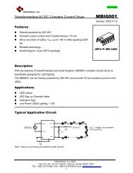
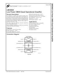
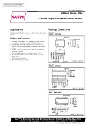
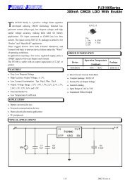
<strong>DS96177</strong><strong>RS</strong>-<strong>485</strong>/<strong>RS</strong>-<strong>422</strong> <strong>Differential</strong> <strong>Bus</strong> <strong>Repeater</strong>General DescriptionThe <strong>DS96177</strong> <strong>Differential</strong> <strong>Bus</strong> <strong>Repeater</strong> is a monolithic integrateddevice designed for one-way data communication onmultipoint bus transmission lines. This device is designed forbalanced transmission bus line applications and meets EIAStandard <strong>RS</strong>-<strong>485</strong> and <strong>RS</strong>-<strong>422</strong>A. The device is designed toimprove the performance of the data communication overlong bus lines. The <strong>DS96177</strong> has an active high Enable.The <strong>DS96177</strong> features positive and negative current limitingand TRI-STATE ® outputs for the receiver and driver. The receiverfeatures high input impedance, input hysteresis for increasednoise immunity, and input sensitivity of 200 mV overa common mode input voltage range of −12V to +12V. Thedriver features thermal shutdown for protection from linefault conditions. Thermal shutdown is designed to occur at ajunction temperature of approximately 160˚C. The driver isdesigned to drive current loads up to 60 mA maximum.The <strong>DS96177</strong> is designed for optimum performance whenused on transmission buses employing the DS96172 andConnection Diagram8-Lead Dual-In-Line PackageDS96174 differential line drivers, DS96173 and DS96175differential line receivers, or DS96176 differential bus transceivers.Featuresn Meets EIA Standard <strong>RS</strong>-<strong>422</strong>A and <strong>RS</strong>-<strong>485</strong>n Designed for multipoint transmission on long bus lines innoisy environmentsn TRI-STATE outputsn <strong>Bus</strong> voltage range −7.0V to +12Vn Positive and negative current limitingn Driver output capability ±60 mA maxn Driver thermal shutdown protectionn Receiver input high impedancen Receiver input sensitivity of ±200 mVn Receiver input hysteresis of 50 mV typicaln Operates from single 5.0V supplyn Low power requirementsFunction TableOctober 1993<strong>Differential</strong> Inputs Enable OutputsA–B E T Y ZV ID ≥ 0.2V H H H LV ID ≤ −0.2V H L L HX L Z Z Z<strong>DS96177</strong> <strong>RS</strong>-<strong>485</strong>/<strong>RS</strong>-<strong>422</strong> <strong>Differential</strong> <strong>Bus</strong> <strong>Repeater</strong>DS009644-1Top ViewOrder Number <strong>DS96177</strong>CNSee NS Package Number N08ENote: T is an output pin only, monitoring the BUS (RO).H = High LevelL = Low LevelX = ImmaterialZ = High Impedance (off)TRI-STATE ® is a registered trademark of National Semiconductor Corporation.© 1999 National Semiconductor Corporation DS009644 www.national.com
Absolute Maximum Ratings (Note 2)If Military/Aerospace specified devices are required,please contact the National Semiconductor Sales Office/Distributors for availability and specifications.Storage Temperature RangeCeramic DIP−65˚C to +175˚CMolded DIP−65˚C to +150˚CLead TemperatureCeramic DIP (Soldering, 60 sec.)300˚CMolded DIP (Soldering, 10 sec.)265˚CMaximum Power Dissipation (Note 1) at 25˚CMolded Package930 mWSupply Voltage 7.0VInput Voltage 5.5VRecommended OperatingConditionsMin Typ Max UnitsSupply Voltage (V CC ) 4.75 5.0 5.25 VVoltage at any <strong>Bus</strong> Terminal(Separately or Common −7.0 12 VMode) (V I or V CM )<strong>Differential</strong> Input Voltage(V ID ) ±12 VOutput Current HIGH (I OH )Driver −60 mAReceiver −400 µAOutput Current LOW (I OL )Driver 60 mAReceiver 16Operating Temperature (T A ) 0 25 70 ˚CNote 1: Derate molded DIP package 7.5 mW/˚C above 25˚C.Electrical Characteristics (Notes 3, 4)Over recommended temperature, common mode input voltage, and supply voltage ranges, unless otherwise specifiedSymbol Parameter Conditions Min Typ Max UnitsDRIVER SECTIONV IH Input Voltage HIGH 2.0 VV IL Input Voltage LOW 0.8 VV IC Input Clamp Voltage I I= −18 mA −1.5 V|V OD1 | <strong>Differential</strong> Output Voltage I O= 0 mA 6.0 V|V OD2 | <strong>Differential</strong> Output Voltage R L= 100Ω, Figure 1 2.0 2.25 VR L= 54Ω, Figure 1 and Figure 2 1.5 2.0∆|V OD2 | Change in Magnitude of <strong>Differential</strong> R L= 100Ω, Figure 1 ±0.2 VOutput Voltage (Note 5)R L= 54Ω Figure 1and Figure 2V CM= 0VV OC Common Mode Output Voltage (Note 6) R L= 54Ω or 100Ω 3.0 V∆|V OC | Change in Magnitude of Common Mode Figure 1 ±0.2 VOutput Voltage (Note 5)I O Output Current with Power Off V CC= 0V, V O= −7.0V to +12V ±100 µAI OZ High Impedance State Output Current V O= −7.0V to +12V ±50 ±200 µAI IH Input Current HIGH V I= 2.7V 20 µAI IL Input Current LOW V I= 0.5V −100 µAI OS Short Circuit Output Current V O= −7.0V −250(Note 10) V O= 0V −150 mAV O= V CC 150V O= 12V 250I CC Supply Current No Load Outputs Enabled 35 mAOutputs Disabled 40RECEIVER SECTIONV TH <strong>Differential</strong> Input V O= 2.7V, I O= −0.4 mA 0.2 VHigh Threshold VoltageV TL <strong>Differential</strong> Input Low V O= 0.5V, I O= 8.0 mA −0.2 VThreshold Voltage (Note 7)V T+ −V T− Hysteresis (Note 8) V CM= 0V 50 mVV IH Enable Input Voltage HIGH 2.0 VV IL Enable Input Voltage LOW 0.8 Vwww.national.com 2
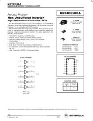
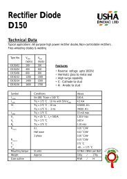
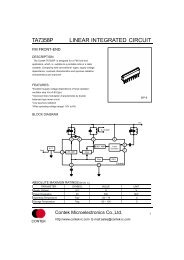
Receiver Switching Characteristics (Continued)Note 8: Hysteresis is the difference between the positive-going input threshold voltage, V T+ , and the negative going input threshold voltage, V T− .Note 9: Refer to EIA Standards <strong>RS</strong>-<strong>485</strong> for exact conditions.Note 10: Only one output at a time should be shorted.Parameter Measurement InformationDS009644-2FIGURE 1. Driver V OD2 and V OCFIGURE 2. Driver V OD2 with VaryingCommon Mode VoltageDS009644-4DS009644-3FIGURE 3. Receiver V OH and V OLDS009644-5FIGURE 4. Driver <strong>Differential</strong> Output Delay and Transition TimesDS009644-6DS009644-7FIGURE 5. Drive Propagation TimesDS009644-8www.national.com 4
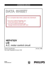
Parameter Measurement Information (Continued)DS009644-9FIGURE 6. Driver Enable and Disable Times (t PZH ,t PHZ )DS009644-10DS009644-12DS009644-11FIGURE 7. Driver Enable and Disable Times (t PZL ,t PLZ )DS009644-14DS009644-13FIGURE 8. Receiver Propagation Delay Times5www.national.com
Parameter Measurement Information (Continued)DS009644-15DS009644-16DS009644-17DS009644-18FIGURE 9. Receiver Enable and Disable TimesDS009644-19Note 11: The input pulse is supplied by a generator having the following characteristics: PRR = 1.0 MHz, duty cycle ≈ 50%, t r ≤6.0 ns, t f ≤ 6.0 ns, Z O = 50Ω.Note 12: C L includes probe and stray capacitance.Note 13: <strong>DS96177</strong> Enable is active high.Note 14: All diodes are 1N916 or equivalent.www.national.com 6
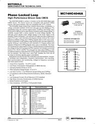
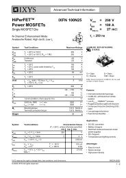
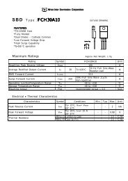
Typical ApplicationDS009644-20The line length should be terminated at both ends in its characteristic impedance.Stub lengths off the main line should be kept as short as possible.<strong>Repeater</strong> control logic not shownFIGURE 10.7www.national.com
<strong>DS96177</strong> <strong>RS</strong>-<strong>485</strong>/<strong>RS</strong>-<strong>422</strong> <strong>Differential</strong> <strong>Bus</strong> <strong>Repeater</strong>Physical Dimensions inches (millimeters) unless otherwise notedMolded Dual-In-Line Package (N)Order Number <strong>DS96177</strong>CNNS Package Number N08ELIFE SUPPORT POLICYNATIONAL’S PRODUCTS ARE NOT AUTHORIZED FOR USE AS CRITICAL COMPONENTS IN LIFE SUPPORT DE-VICES OR SYSTEMS WITHOUT THE EXPRESS WRITTEN APPROVAL OF THE PRESIDENT OF NATIONAL SEMI-CONDUCTOR CORPORATION. As used herein:1. Life support devices or systems are devices or systemswhich, (a) are intended for surgical implant intothe body, or (b) support or sustain life, and whose failureto perform when properly used in accordancewith instructions for use provided in the labeling, canbe reasonably expected to result in a significant injuryto the user.2. A critical component is any component of a life supportdevice or system whose failure to perform can be reasonablyexpected to cause the failure of the life supportdevice or system, or to affect its safety or effectiveness.National SemiconductorCorporationAmericasTel: 1-800-272-9959Fax: 1-800-737-7018Email: support@nsc.comwww.national.comNational SemiconductorEuropeFax: +49 (0) 1 80-530 85 86Email: europe.support@nsc.comDeutsch Tel: +49 (0) 1 80-530 85 85English Tel: +49 (0) 1 80-532 78 32Français Tel: +49 (0) 1 80-532 93 58Italiano Tel: +49 (0) 1 80-534 16 80National SemiconductorAsia Pacific CustomerResponse GroupTel: 65-2544466Fax: 65-2504466Email: sea.support@nsc.comNational SemiconductorJapan Ltd.Tel: 81-3-5639-7560Fax: 81-3-5639-7507National does not assume any responsibility for use of any circuitry described, no circuit patent licenses are implied and National reserves the right at any time without notice to change said circuitry and specifications.