Un ed States Patent
Un ed States Patent
Un ed States Patent

You also want an ePaper? Increase the reach of your titles
YUMPU automatically turns print PDFs into web optimized ePapers that Google loves.
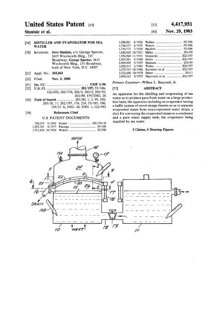
<strong>Un</strong> <strong>ed</strong> <strong>States</strong> <strong>Patent</strong>S~c et al.Ill] 4,417,951~ Nov. 2~ 1983[54] DISTILLER AND EVAPORATOR FOR SEA I~8~861 6/1926 Walker ...............................55/186WATER1fl2~5378/1929Waters...............................55/1861fl7~7737/1930Hackett..............................55/186[76] Inventors: Jovo Stani~ c/o George SpectoL 1~2~42810/193! Miller ...............................203/993615 Woolworth Bldg., 2331)3~96411/1933Gensecke............................202/197Broadway; George Spectoh 3615~201~61 5/1940Stoltz...............................202/197Woolworth Bldg., 233 Broadway, ~90~509 9/1959Helmers..............................203/99both of New York, N.Y. 100073~2~215 2/1962Weber...............................202/1973,279,533 10/1966Kersteteret al ....................202/197[21]Appl. No.: 20a,0633,532,606 10/1970Sibert...............................203/1~69~3219/1972Marovichet al ...................202/197[22] Fil<strong>ed</strong>: Nov. 3, 1980Prima~ Examiner--Wilb~ L. B~com~ J~[51] InL Cl) ................................................C02F 1/04[52] U.S. Cl .......................................202/197; 55/18~ABSTRACT122/492; 202/17~ 203/1; 203/2; 203/10;An appar~us ~r the ~stilhng and evap~ating of sea203/40; 159/DIG. 26water so ~ produce pu~ ff~h w~er on a large produ~[58] Field of Search ................... 203/40, 1, 2, 99, 100,fion bails; the appar~us ~u~ng an evapor~or hav~g203/10, 11; 202/197, 17~ 234; 55/185, 18~159/27 A, DIG. 2~ DIG. I; 122/492a ba~e sy~em of novd defign ther~n so as to separateevapor~<strong>ed</strong> steam from nomevapor~<strong>ed</strong> water drop~ a[56] References Cit<strong>ed</strong>du~ ~r conve~ng the evapom~d ~eam ~ a conden~rU.S. PATENT DOCUMENTSand a pure water sup~y ~n~ the evapor~or bring700~74 5/1902 Roake .............................202/185 Dsupp<strong>ed</strong> by ~a w~e~1~2~I01 4/1917 Pac~ga .................................55/1861,511,854 10/1924 W~ers ..................................55/1864
U.S. <strong>Patent</strong>Nov. 29, 1983 4,417,951
4,417,951DISTILLER AND EVAPORATORFOR S~drMns water from the evapormor when ff~becomesheavily saturat<strong>ed</strong> with brin~ Another drainpipe 16 withWATER ’ a colMction canM 17 ~ a ring plme 15 colMc~ nonevaporM<strong>ed</strong>brine water droplets. ~ :T~s ~vem~n r~es g~em~y m eq~pmem ~r ~e 5 The evaporator ~ provid<strong>ed</strong> wffh a water Mv~ gauge~ation and ~~ ~ ~a w~ ¯ 18, vacuum gauge 1~ a manom~er 19A and a s~om~It h wall known that ~th inc~as~g ~p~ the~ te~ , ~ ....is an ~c~g ~n~m~ of drin~ng w~er, and In the evaporator, the steam space 24 g ~NMd withwkh a g~ ~fi~z~o~ ~e ~ a h~ amoum baffles 2~,21 and 22, for the evapora~d ~eam. The10 purpose of the baffles N to separNevaporat<strong>ed</strong> steamof pure water ~q~d ~ various en~rg<strong>ed</strong> and newph~es of manu~ufing W~u~. Accor~n~% ~om non-evapor~<strong>ed</strong> water drops wh~h are not asthere ~ ~ a more ne<strong>ed</strong> to find other sources of jet-pure as distilMd ~eam. Each baffle 2~ and 21 aspu~ w~ than ~ pr~enfly b~ng o~n<strong>ed</strong> from ~k~, shown in FIG. 2, has ope~ngs 23 of diffuser shape.rivers and the 1~ pa~u~fly ~ ~ew that more and Such diffuser-shap<strong>ed</strong> openings acc~r~e the separ~nmore of k ~ ~ p~l~<strong>ed</strong> due to chem~s of l~ of saturat<strong>ed</strong> ~eam. The last component baffle 22 forms~du~ and w~te of mod~n ~v~g b~ng dump<strong>ed</strong>~ d~oy~g the n~ur~ puny of such waterbo~. It i~ ~e~, n~ur~ ~ a~enfion ~ nowa Nst barrier for non~vaporat<strong>ed</strong> water drops and fordisti~<strong>ed</strong> geam before entering steam space 2& Thebaffle surNce N equM ~ area to the ~Nde transverseb~ng ~ven to obt~n pur~ flesh w~ o~ of s~y ~a area of the evapor~or, and is arcuate for more effectivew~ ~ ~ me~ ~e p~nt day ~q~me~s. In ~me 20 separ~ion of distill<strong>ed</strong> ~eam. The lowermo~ baffle 2~countries flesh water ~ ration<strong>ed</strong> pa~afly ~ dry or has the Nrge~ surNc~ and on ~s peripherN <strong>ed</strong>ge has ahot season~colMcting vault 25 in which non-evapor~<strong>ed</strong> waterAccor~n~ ~ ~ a prin~p~ o~e~ of the w~em drops colMct and are convey<strong>ed</strong> to the drNn canM 17 ~~vem~n ~ prov~e an ~W~ ~s~Mr and evapor~tot ~r converting sea w~ ~ pure ff~h w~. 25 througri hng plat~h~5~iffuseE rVap°ratesh dape~teao mpeNnf~s°m2;reaand2~hePnAnther o~e~ h to pin,de a distiller and evaporator~r ~a w~ w~ch ~ one pa~uhr deign can be ~g coupe and b~ng partly dives~d of water drop~#nge on the second component baffle 21 while changus<strong>ed</strong>aboard a sh~ whe~ ~ t~s time there ~ a gre~ After g~ng through the openings 23 of the secondwa~e of he~ by ~e exhau~ g~ of ~e large en~n~baffle 21 pure steam and non-evaporat<strong>ed</strong> water dropspas~ng out of the s~p ~nnd and ~to the ~mosphe~, 30 are separ~<strong>ed</strong>, the pure ~eam then Maving ~eam spaceand wh~n t~s w~d heat ~ the ~nnd can be h~ness<strong>ed</strong>to produce ~ of the s~s ~q~mem of ~h24 through outlet pipe 14 to the condenseLTwo or more baffles ~ a same evapormor may bewater during an ocean voyag~ ~t any ad~fion~expens~ The ~a w~ us<strong>ed</strong> ~ co~ ~e en~n~ can beemploye~ as may be req~r<strong>ed</strong> for ma~mum effect.us<strong>ed</strong> as ~ ~ ~ready p~e~<strong>ed</strong> ~ to 45 degrees cen~ 35 In FIG. ~ a mottle design of ~ffuser opening 23 ~grad~ so it ~ ready ~r ~o~n.provid<strong>ed</strong> by a diffuser 30 of Venturi shape wffh dectriccontac~ 31 and 32 on 0ppo~te ~des so thin ~rge w~erO~ o~ec~ are to pro~de a distiller and evaporator~r ~a w~ w~ch ~ ~m~e in deign, inexpensiv<strong>ed</strong>rops entering the same will dose an dectric~c~t~ manu~ rugg<strong>ed</strong> in con~ru~ easy to use andthat will thus cause a spark thin will vaporize the w~ereffl~em ~ ~.40 drop. Thus preventing water drop passage therethrough.Contact 31 ~ ~ationary whim contact 32 isThese and ~~s ~1 be ready e~dem upona ~udy of the ~l~w~g ~e~fic~n and the accomp~ slidable closer ~her~o where ~eam pre~ure ~de arean~ng ~a~ wh~n26 is increas<strong>ed</strong>, at wh~h time there are Mrger concentrationof w~er drops so that they must be vaporiz<strong>ed</strong>.FIG. 1 ~ a ~mmm~c ~de vMw of a sy~em of the~em ~venfion.45 T~s ~ accomplish<strong>ed</strong> by a hollow accordian shap<strong>ed</strong>,FIG. 2 ~ an e~g<strong>ed</strong> det~ ~ cross section of ~e expandable case 33 interconnect<strong>ed</strong> to area 2~ andim~r baffle co~u~n ~e ~o~ t~ ~ong which pushes a #votabM lever 34 connect<strong>ed</strong> to slide 35section 2--2 of FIG. 1.which carries contact 32.FIG. 3 ~ a ~p ~ew ~ ~e baffle con~rucfion ~de While various changes may be made in the d~ilthe evapor~o~ as ~ew<strong>ed</strong> ~ direction 3--3 of FIG. 1. 50 construction, ff ~ unde~tood that such changes will beFIG. 4 ~ a cross secfion~ew on fi~ 4--4 of FIG. within the s#rit and scope of the present ~vention as ~1. defin<strong>ed</strong> by the append<strong>ed</strong>Mms.FIG. 5 is an e~g<strong>ed</strong> cross secfion~ ~ew on fine The following ~ dMme~5--5 of FI~ ~ ~o~ a peripher~ dr~nage can~. 1. A Sea water distiller comprising a sea w~er supplyFIG. 6 ~ a mo~ficafion of the ~venfion show~g a 55 tank connect<strong>ed</strong> by a conduito the bottom of an evaporatorwith heating mean~ ~duding a ring plmecross section ~rough a mottl<strong>ed</strong> ~se~. The proem ~vent~n is ~own ~ FIG. 1 to ~ude mount<strong>ed</strong> around the ~de periphery of sMd evaporatoran evapor~or 10 and a sea water sup~y water tank 11 at a pr<strong>ed</strong>~erm~<strong>ed</strong> levd, s~d ring pl~e ~u~ng aw~ch are ~onne~<strong>ed</strong> by a sup~y ~pe 12 ha~ng a pefipher~ dr~nage can~ ~ com~nation with a pluralsup~yv~ve 1~ w~ch ~ a~om~c~y ~g~<strong>ed</strong> by 60 Ry of spac<strong>ed</strong> venally curvate baffles above s~d pl~¯ e water Mvd ~t~n the evaporato~ The ~p of the the lowermo~ of s~d baffles having a peripher~ <strong>ed</strong>geevapor~or ~ connect<strong>ed</strong> w~h a condenser ~ot show~ portion<strong>ed</strong> above and l~er~ly adjacent s~d can~by a ~pe 14 ~r ~u~ ~o~ steam ~to ~econdenser whe~ a vacuum ~ o~n<strong>ed</strong> by vacuum ~e~whereby moi~ure ~ direct<strong>ed</strong> and dron<strong>ed</strong> from s~dbaffle to s~d can~, ~ fu~her combination with a dr~ntor~~ ~ow~. Condens<strong>ed</strong> water from a condens<strong>ed</strong>65 age pipe having an inl~ ~ commu~c~n wffh s~dsuction pump ~ show~ ~k~ wa~r and discharges k~ drin~ng w~er mn~ ~ ~ow~. A dr~n ~pe ~show~ ~ the b~mm of the evapor~or periodicallycanM for drayage purposes, sMd baffles having upwardorient<strong>ed</strong> diffusers and an upper solid baffle superimpos<strong>ed</strong>over sMd baffles with the diffuser~ sMd upper2
3baffle having an outer <strong>ed</strong>ge spac<strong>ed</strong> from evaporator~ner sur~ce whereby deflect<strong>ed</strong> ~eam vapor ~ direc~dpefipher~ly to the s~d <strong>ed</strong>ge and to a ~eam space aboves~d upper baffle ~duding a ~eam outlet above s~d~eam space wheron s~d diffusers ~duding means forvafia~y restrict~g water drops from pas~ng therethroughcompiling a Vemufi sect~n in s~d diffusers4,417,9514wi~ O~c~ m~ns ~ ~e Ve~ufi ~n ~r v~ofiz-~g water drops upon con~ of sa~ de~fic~ meanswith water drop~2. A ~sfil~r ~ ~ clam 1 wh~n s~d de~fic~means include ~e~fic con~ vafia~y spac<strong>ed</strong> respon-~ve to steam pressure.10152o253O355055
<strong>Un</strong> <strong>ed</strong> <strong>States</strong> <strong>Patent</strong>EII~ J~Ill]<strong>Patent</strong> Number:~ Date of PatenUWATER DEGASIFICATION AND3,479,949 11/1969Reynoldset al ......................99/295DISTILLATION APPARATUSL53L60610/1970Sibert...............................202/180L83E016 9/1974Powers...............................~ Invento~202/181John ~ EIH~ J~ 1084 P~m~ Ave, L935,0771/1976Dennison............................202/180LarchmonL N.Y. 10538~081~31 3/1978Weiss................................202/181~1] Ap~. N~: 48~767~13L984 1/1979Kirschmann..........................202/83~17~84212/1979Vitous...............................99/295~ ~l<strong>ed</strong>: Ap~ 2~ 1983~18~150 2/1980Rich............................203/DIG. 16~24L369 1/1981Bean................................202/181Rd~<strong>ed</strong> ~ A~ ~~25~616 2/1981Glazer...............................202/181~261fl964/1981Lemoine.............................202/181C~u~a~ ~ ~ No. 26~88~ Ju~ 3, 1981, ~269~63 5/1981McFee................................202/202Pa~ N~ ~3~.~41~95111/1983Stanisicet al .......................202/197~42~37412/1983Ellis................................202/176~1] InL ~? ...........................B01D 3/0~ ~2F 1~[5~ ~ ~ .....................................~ 202/18~FOREIGN PATENT DOCUMENTS202/181; 202/185.5; 2~/188; 202/19~202/197; 202/202; 202/23~ ~2~ ~203/1~ 203~ 203/2~ 203/DIG. 16;109551 1/1940 Amtmha .............................202/196Prima~ Examiner~Wiibur B~comb~ 22 Attorney, Agen~ or Firm--Eugene E Geoffre~ JL~ ~fld of Seth ..................... 202/188, 185.5, 17~ABSTRACT202/19~ 2~ 19~ 181, 18~ 83, 19~ 19~ 19~195, 202; ~. 17, 1~ I1, DIG. 2~ 2~ W~er deg~ific~n and ~stillation apparatus ha~ng aDIG. 16; 99/295 cont~ner ~r wa~er to be dega~fi<strong>ed</strong> and ~still<strong>ed</strong>, a~ R~ ~t<strong>ed</strong>~lativ~y small boiler a~ng s~d container and ha~~g a first condor e~en~ng ~to the cont~ner so thin a~S. PATENT DOCUMENTSs~e~<strong>ed</strong> wmer ~v~ ~ ~e confiner will fill s~d boiler284~II 8/1883Her~ck .......................~3~ 17 to a s~ec~d h~ght, a condenser w~n the con~er771,832 I~19~ R~ ..............................~I~ and immer~d ~ the water contain<strong>ed</strong> there,, a second851,~5 ~1907 ~ck ................................20~/196 cond~t e~en~ng ~om the space above the water ~9~9,6259/1910Ho~et ~ .....................2~/I~ s~d b~r to the ~t of the condense, an outlet on theI~I~508 2/1911 ~Cu~ ..............................202/196 condenser ex~n~ng ~rough a cont~ner w~] for ~~13~8 10/1938 Kess~ .................................202/1892~75~82 7/1949~em~s ..............................202/194char~ng dega~fi<strong>ed</strong> and ~s~d water and heating3~2~214 2/1962B<strong>ed</strong>uhn e~ ~ ....................203~0 X means m s~d boiler for heating the water therei~3~2~215 2/1962W~er ...............................203~ X3~4~305 ~1966 W~|~m~n .....................202/19~ X
U.S. Patem s~ 1~ 1~6 ~t3 ~S 4~12~90
U.S. <strong>Patent</strong> se~ 16, 1986 She~ 4 of 8 4,612,090
U.S. <strong>Patent</strong> se~ 1~ 1986 She~5 of 8 4,612,090
~S. Patem sev 16, 1986 S~ 6 ~8 4~12~900 o 0
-U.S. Palm s~ 16, 1986 S~ 7 a8 4~12~900
U.S. <strong>Patent</strong> se~ 16, 1986 She~ 8 of 8 4,612,090
~61~090A s~l ~h~ o~e~ of the invention re,des ~ theWATER DEGA~CA~ON AND D~LLA~ON prov~ion of a novd and ~ wm~ d~c~APPARATUSand d~t~n apparatus char~ri~d by ~s ~m~ff~ ~ ~~ and mMn~nance and r~mi~y ~wTMs ap~m~n ~ a continuation-in~a~ cf applic~ 5 cos~tion Se~ N~ 269,880 ~<strong>ed</strong> June 3, 1981 entitl<strong>ed</strong> "Wmer A s~l ~h~ o~e~ of the ~vention ~Nd~ ~ theDegasification and D~tillm~n Apparatus" now U.S. provM~ ~ a ~vd ~d ~pro~d b~ ~r ~e ~s~Pro. No. ~42~37~fion of water wNch mi~m~ ~e accum~ation ofTh~ ~vention r~a~s to d~ng apparmus and mo~ ~am ~ the b~er caus<strong>ed</strong> by sNt~ d~e~ and otherspe~ficflly to novd and improv<strong>ed</strong> water ~fl~tion10 water ~ma~ms wMch can ~nm~ the waterapparatus.bNng ~s~&Known ~sti~ng apparmus generally ~v~ve ~eutil~m~n of a dos<strong>ed</strong> boiler and means ~r continuoufly ~c~dan~ ~ ~e ~v~fion ~ud~ a ~n~r ~~e~ng wmer to the boiler. As the wmer ~ the boil~ m m~ ~d ~ ~c~ ~e wm~ ~ ~ ~s~d. A ~heat<strong>ed</strong> to produce wmer vapor or ~eam, v~ati~ cherub15 b~Mr ha~ng he~ng demems mourn<strong>ed</strong> ~on ~ p~Gc~ componen~ of water ha~ng boiling p~nts ~wer e~ secur<strong>ed</strong> to one ~de of the rank and a fl~d condMtcou#~ ~e bMMr ~ ~e rank ~ ~ ~e l~d Mvdthan the wmer will boil off and combine with the steam.The steam tog~her with the v~a~e vaporiz<strong>ed</strong> chemic~compone~s will then be condens<strong>ed</strong> ~ a s~tab~m ~e b~ ~H be conffdMd by ~e fiq~d Mvd ~ ~econdenser so that the ~sdm~ ~s~ wffi cont~n the 20 a__condense~ ank" A ~eam~o~ly~and ~ap°r ~d°Ufl~ ~ ~nthe b~er~ ~mkeou#<strong>ed</strong> tov~a~e chemic~ In ca~s wher~n ~e wmer has a outlet of the conden~r ex~nds ~rough the w~ of th<strong>ed</strong>isagreeable odor produc<strong>ed</strong> by s~phur compounds and tanZ The conden~r may be ~ ~ such a mann~~m ~e hq~d ~ ~e mk ~H ~r pm ~ ~ ~ ~ethe ~k~ known apparatus ~nds to concentra~ the odorcondenseL ~ ~ a~mm and wffh the heatersanp drior u.sm āke th;a~WateNr~ eve4, n33~30m 7°~fUlg "ran~d j~yApN~ant’l s3, 1982 25 ~ ~e bMMr ~g ~ ~e ~uM ~ ~e ~r ~Hen~tl<strong>ed</strong>: "D~tillm~u Apparmuf’ dNcloses distiNng heat Mmo~ ~anmneoufly and ~em ~H be ~ outappar~us embod~ng upper and ~wer chambers with ¯rough the condenseL As the p~e wff~ thethe condenNng coil ~spo~d ~ the upper chamber b~er exce<strong>ed</strong>s the capm~ of the outlet to rec~vewMch N normally fill<strong>ed</strong> wi~h w~er and graduNly ~d steam or water v~oL p~u~ will ~e water in theinto the ~wer chamber wNch N heat<strong>ed</strong> by a s~tab~means ~ order to prodnce geam. The steam g then ~d~ ~ ~& wm~ ~H ~Mn ~w ~o ~e b~upwardly through a condenser ~ the upper chamberand ~ then discharg<strong>ed</strong> ~om the condenser as a ~q~& ~ of the d~ apparatus. ~nee hot wmer ~By opiating the apparmus ~r a sho~ period of time 35 b~ c~smfly ~d ~ ~e mk and ~ ~m ~prior to the co~ection of the ~<strong>ed</strong> wate~ the condens~w~ ~cre~e ~e ~mperature of the wa~r ~ thecon~anfly ~mov<strong>ed</strong> ~om the c~m~ by ~e w~er~t~n ~e tanL ~e w~ wi~ ~e tank w~ ~e~eupper chamber ~nd bNl off vMa~e chemicN comp~ ~ mm~e and b~ off ~M ~e~c~ ~nent~tMn<strong>ed</strong> ~ ~e wm~ prior m ~s~lm~n ~e~o~ C~dTh~ ~vention constitutes an improvement over prior~ water ~ ~r~y ~d to ~e mk at ~e ~Mt to theknown ~stilling apparatus ~u~ng the apparmus d~dos<strong>ed</strong>~ apN~ant’s prior U~d Stat~ pment ~ Ihm ~ time ~e b~ ~ ~M~ Means may M~ be pro~d~b~ler so that the boiler wiB ree~ve cold wmer ~hembod~s a novd and improv<strong>ed</strong> smNI bNler ~ud~g ~ a~o~afion w~h the rank ~r ~e~ng condens<strong>ed</strong> ~instantaneous ~eating mean~ a conden~r ~nd a re~b ~Md ~d ~g~d ~ ~m ~e~ ~s ~rvNr wNch pro~d~ ~n a~omatic supNy ef wm~ to the 45 ma~ng co~ tea or merdy pro~de hot wmer ~rbN~r and may Nnction to con the condenser. With other pu~th~ arrangement, lhe water ~ the ~rvN~ ~ w~ be The ~ove and other ~ec~ and advanmg~ of theshowm ~rcMm~ m and from the boiler to repeme~y ~v~ti~ w~ become mo~ appa~m ~m the ~w-~rrupt boiling and hem thus impal<strong>ed</strong> lo the wmer ~ ~g ~ri~ and ~mpan~ d~ ~rm~g¯ e re~rvNr tog~her w~h ~e hem m ~t pa~ of ~ pa~ of t~s ~#c~.wMch may be impal<strong>ed</strong> by the condenser wffi heat thewater in the ~rvNr to a ~mperatu~ that w~ effectivdyboil off chemicN constituents of the water and FI~ 1 ~ a ~agmemary p~ ~w ~e m~mm~ ~E D~N~the time req~d for operation of the ~stil~r ~ order ~ ~ d~g ~m ~ ~e ~h ~ ~to produce a ~stillate free of the m~als and undesirab~ 55 tio~odors ~ mmeriN~ r<strong>ed</strong>uc<strong>ed</strong>.FIG. 2 ~ a ~o~ ~ctionM ~ew of FIG. 1 ~ ~Another o~ect of the ~vention reNdes ~ the provi- the ~ne 2--2 ~e~o~~on of novd and improv<strong>ed</strong> wmer dgtiHation apparmus FIG. 3 ~ a cro~ ~ctionM ~ew of FIG. 1 token MongwNch not o~y avNds co~rM means for fe<strong>ed</strong>~g wm~ the ~ne 3--3 ~e~and ~t~ ~ ~cd~ meansfrom a re~rvoir ~o a bNler but also embodi~ an arrangeme~and orga~zation of ~ements wher~n all FIG. 4 ~ a cro~ sectionM ~ew of the b~er and a60 cam<strong>ed</strong> by the comMne~potions of both the reservoir and boiler are readily ~agmemary po~on ~ the tank token ~ong the l~eacc~s~ for ~ea~ng and m~ntenanc~~ thereof of FIG. ~A still N~her o~e~ of the ~vention reNdes ~ the FIG. ~ ~ a ~de d~M ~ew of a mottl<strong>ed</strong> emprovisionof hot ~stil~d and sub~antially odobffee65 bo~mem of ~e ~vem~n ~r produ~ng d~Md wm~water ~r the brewing of coffee and ~a ~ well as for use ~r ~e and other ~od~~n the preparation of other ~ods such as soups and the FIG. 6 ~ a cro~ ~ctionM ~ew of FIG. 3 token Mong~k~the ~e a--6 m~eo~2
3~61~090FIG. 7 ~ a fide devafionfl ~ew ~ parti~ section of 41 and the boiler can be readily disassem~<strong>ed</strong> for deaning.The heating dements 13 and 14 in the ~ant em-the water tank and b~Mr of FIG. 5;FIG. 8 ~ a cross ~ction~ew of FIG. 5 taken ~ong bo~ment of the ~vention are carri<strong>ed</strong> by the w~141 andthe line 8--8 thereo~are connect<strong>ed</strong> in series by a lead 44 connecting oneFIG. 9 ~ a cro~ sectional ~ew ~ pe~pective of a 5 ~rmin~ of one heater to one term~ of the othermo~fi<strong>ed</strong> embo~ment of a d~fiNer ~ accordance wkh heate~ The power ~ne 45 has one lead 46 connect<strong>ed</strong> tothe invenfio~the other ~rm~ of the he~er 14 while the second leadFIG. 10 ~ a fragmentary crcss ~ction~ew of still 47 ~ connect<strong>ed</strong> through a thermo~ 48 to the otheranother embo~ment of the ~ventio~termin~ of the heater 13. The thermo~ is moun~d onFIG. 11 ~ an dev~ion~ ~ew of the water Mvd 10 a bracket 49 ~ dose pro~mky to the heater 13 and incontrol of FIG. 1~the even the heater 13 reaches a ~mperature above theFIG. 12 ~ an devation~ ~ew ~ partifl section taken norm~ operat~g ~mperatur~ the thermo~at will operateto open the drc~t and d~energ~e both heaters 13~ong the Nne 12--12 of FIG. 1~FIG. 13 is a cross sectionfl ~ew of FIG. 12 taken and 1~ R ~ evident however that heaters 13 and 14flong the l~e 13--13 thereo~15 cord be arrang<strong>ed</strong> for paralld operation or ~ the ~te~FIG. 14 ~ a cross section~ew of FIG. 13 taken nativ~ a ~ngle he~er may be employ<strong>ed</strong> provid<strong>ed</strong> howeverk drivers the quantky of heat necessary for oper~~ong the fine 14--14 thereo~ andFIG. 15 ~ a top ~ew ~ parti~ section of the boiler tion of the apparatu~shown ~ FIG. 10.If de,r<strong>ed</strong>, the tank or cont~ner 10 may be prov~<strong>ed</strong>Re~rring now to the drawings and more sp<strong>ed</strong>fic~ly 20 with a convention~ cover having openings therdn or ~to FIGS. 1 through ~ the ~g apparatus ~ acco~ the ~ternative may util~e forc<strong>ed</strong> ~r Orculation meansdance with the ~vention compds~ a cylindric~ tank or for the remov~ of unde~rable vapo~ Hbera~d from thecont~ner 10 ha~ng a p~r of handMs 11 secur<strong>ed</strong> to the Nquid w~hin the tank 10 during the course of the d~tillationprocess. One embodiment of air circulating meansfide thereo£ A boiler 12 ha~ng in~antaneous heatingdements 13 and 14 ther~n ~ affix<strong>ed</strong> to the fide of the25 ~ illustrat<strong>ed</strong> in FIG. & The ~r drculating means ifidudesan ~ve~<strong>ed</strong> dish<strong>ed</strong> cover gener~ly denot<strong>ed</strong> bytank 10 by the fl~d connectors 15 and 1~ The fl~dconnector 15 ~dud~ an ~bow 17 ha~ng a sho~der 18 the numer~ 50 which ~dudes a flat upper wall 51, anand a thread<strong>ed</strong> shank e~en~ng through cooperm~g upwardly extending pefipher~ wall 52 and a downwardlycurv<strong>ed</strong> peripher~ w~l 53. The lower peripher~ope~ngs ~ the wall 19 of the b~Mr 12 and the wM1 ofthe tank 10. A nut 20 engages the shank of the fitting 15 30 <strong>ed</strong>ge of the wMl 53 carries three or more angularlyand tog~her with a resilMnt w~her 21 pro~d~ a wv dispos<strong>ed</strong> rolM~ 54 each having space discs 55 rota~~r-tight seM for both the tank 10 and the b~ler 12. A ably carri<strong>ed</strong> by a sha~ ~ The discs 55 engage thewmer i~ tube 22 ~ fixe~y cou#<strong>ed</strong> to the fitting 13 by rolMd <strong>ed</strong>ge 10’ of the tank 10 and accordin~y providemeans of a nut 23 so that water wren the tank 10 will an annular vent b~ween the cover 15 and the <strong>ed</strong>ges ofbe automaticaNy ~d ~to the b~Mr 12 until the water35 the tank 10.levd wff~n the b~ler co~esponds to the wmer levd ~ The wall 51 of the ~r drculat~g means shown ~the tanL ~ w~ Mso be observ<strong>ed</strong> thin the wmer Mvd ~ FIG. 3 includes a motor gener~ly denot<strong>ed</strong> by the numer~57 which has a sha~ 58 extending through thethe tank ~ pre~raMy mMntMn<strong>ed</strong> m a Mvd to effe~ |olMor ~ Mast sub~antiM immerfion of the heating dements perforat<strong>ed</strong> wall 51 and carries a fan 59. Power ~ f<strong>ed</strong> to13 and ~4 ~ the wmer wff~n the boiler.40 the motor 57 by a ca~e 60 connect<strong>ed</strong> in a convention~The ~eam outlet fltt~g 16 ~ of conventionM con- manner to the moto~ If des~<strong>ed</strong>, sw~ch means may be~ruction and ~dud~ an outlet #pc 24, a thread<strong>ed</strong> provid<strong>ed</strong> for operation of the fan. The fan motor ~shank 2~ ex~nd~g through the walls of the tank and cover<strong>ed</strong> by a dome~hap<strong>ed</strong> houfing 61 securdy fi~<strong>ed</strong> tothe boiler and secur<strong>ed</strong> thereto by a nut 25. A sealing the cover 53 and secur<strong>ed</strong> thereto by any s~ta~e means.w~her 26 ~ d~po~d b~ween 1he tank and the boiler Io45 In the in~ant embodiment of lhe ~vention, the domeshap<strong>ed</strong>houfing 61 ~ adapt<strong>ed</strong> to frictionally engage thepro~de a w~evtight connection. The condenser 27 ~the ~ant embo~ment of the ~vention ~ ~ the form of peripher~ wall 52 of the cover 50. In operation, ~r ~a c~Md tube of m~M such as ~M~s ~<strong>ed</strong>, copper or drawn in through an opening 62 and the perforat<strong>ed</strong> wallthe Nke and has the ~Mt end potion 28 seMably connect<strong>ed</strong>to the fitting 16 wit~n the tank 10. The oufl~ 29 50 in the container and d~charg<strong>ed</strong> through the annular51 whereupon k ~ direct<strong>ed</strong>ownwardly over the w~erof the condenser 27 has a fitt~g 30 ex~nd~g through opening between the container 10 and cover 50.the wall cf the tank 10 and pro~d~ the fl~d oufl~ 31. In the operation of the di~ill~ion apparatus d~The tank fu~her ~dud~ ~n overflow p~e 22 w~ch ~ scrib<strong>ed</strong> abov~ the tank 10 and boiler 12 are fir~ filMdconnect<strong>ed</strong> to a fitt~g 33 seal<strong>ed</strong> to the wMl of the tank 10 with water to a Mvd at Mast substantially covering theand a drMn cock 34 for drM~ng l~d from the tanL A 55 heating dements 13 and 14 as wi~ be observ<strong>ed</strong> morew~er ~Mt vMve 34 ~ card<strong>ed</strong> m the upper potion of the deafly in FIG. 2. R will be observ<strong>ed</strong> th~ when fill~gtank or contMner 10 and has an inlet 3~ an outlet 37 the tank 10, water wi~ automatically flow through conduit22 ~to the boiler so that the Mvd of the water inwithin the tank and a hand-wheal 38 for reg~ating thewmer sup#y ~ order to mMntMn substantially constant lhe lank will be lhe same as the wa~r Mvd in the boile~Mvd of lhe w~er wff~n the tank.60 Energy ~ then suppN<strong>ed</strong> to the heating demen~ 13 andThe boiler ~ shown more deafly ~ FIG. 4 and confi~sof two hous~g demen~ 39 and 40. A drc~ar wMl boiler 12. S~am ~om lhe boiler win emerge through14 which win function to boil the water wkhin theor partition 41 ~ ~spos<strong>ed</strong> b~ween the houfing demen~ the outlet 24 and then flow through the condenser 1739 and 40 and ~dudes a p<strong>ed</strong>pherM seM 42 w~ch ~ and the condens<strong>ed</strong> ~eam will then be d~charg<strong>ed</strong> as ardeasably damp<strong>ed</strong> b~ween the outer alms of the hou~ 65 Hq~d ~om the outlet 31. When initi~ly operating this~g dements 39 and 40 by clips 43 about the periphery apparatu~ k ~ gener~ly defirabM to discard the d~tillateuntil the water within the tank 10 has attun<strong>ed</strong> aof the boiler 12. T~s arrangement com~etely ~Ms thechamber form<strong>ed</strong> by the hous~g posen 39 and the wall normally operat<strong>ed</strong> ~mperature which ~ ra~dly ~-4
5~61Z090tin<strong>ed</strong> in the following manne~ HeMers 13 and 14 are fion a ~m~ircd~ brackm 84 of L6hap<strong>ed</strong> section ~rdefign<strong>ed</strong> to hem the water wit~n the boiler at a rate ¯ dably recoving a basket 85 ~u~ramd ~ brokendines~ster than the condenser 27 can accommodMe the ~ FIG. 5 wMch may normally h~d a fi~er and groundsteam produc<strong>ed</strong>. Accordin~ pressure ~ devdop<strong>ed</strong> coffee. A base 86 engages and suppo~s the Z-shap<strong>ed</strong>within the boiler 12 and will force ~q~d ~om the boiler5 brack~ 72 and ~Oud~ a convenfionM de.fie heatingthrough the tube 22 back ~to the ~nk 1~ As soon as the dement 8% The heating dement 87 ~ prodd<strong>ed</strong> wffhpressure ~ reliev<strong>ed</strong> w~n the boile~ water w~ ag~n suitabl ener#zing conducmn and swim~ng means not~ow through the tube 22 back ~to the b~r w~h the shown so that ff may be turn<strong>ed</strong> on and off as defi~&resdt that there w~ be a perio~c reve~ of water The space b~ween ~e b~mm of ~e basket 85 and ~eflow through the tube 22. T~s action resu~s ~ a sub-10 top of the heating demem 87 ~ of ~ffident magnitude~anti~ ~crease ~ temperature of the wa~r w~n Ihe to ~cdve a s~m~e ~cepm~e 88 ~r ~c~ng b~wCd~nk 10 and contributes to the he~ impal<strong>ed</strong> to the coffee. It ~ ob~o~ ~om ~e ~g~ng d~cus~on thMwMer ~ the ~nk 10 by the action of the condenser 2~ the basket 85 may be a~ang<strong>ed</strong> to aceommodMe teaThe ~mper~ure of the w~er tank 10 however ~ ~- ~aves ~r the brewing of tea or ~ the ~rnative theways brow the boiling ~mperature and shodd pre~ra-15 distill<strong>ed</strong> water ~om the fittMg 83 can be f<strong>ed</strong> ~ctly~y be ~ the range of 180’ F. to 19& ~ ~ order to be ~to ~e ~ce~ac~ 88 ~r making soup or any otherce~n that undesirab~ componen~ ~ the water are purple ~r w~ch purifi<strong>ed</strong> ~s~l<strong>ed</strong> w~ may be ~-boil<strong>ed</strong> off prior to a~u~ d~tiH~n.q~&In one form of the ~vention utilizing a tank 10 hating The cont~ner 70 ~dud~ a ~sh<strong>ed</strong> cover gener~lya v~ume ~f 1 to 2 gallons of w~e~ a b~lCr 12 h~d~g20 denot<strong>ed</strong> by the num~ 89 wMch may be affix<strong>ed</strong> ~ theappro~m~dy 16 ounces of wate~ heating dements contMner 70 by any s~tab~ mean~ The cover 89 ~-deign<strong>ed</strong> to d~fipMe from 1,500 to ~000 wMt~ ~ wffi ~udes an ope~ng 90 for ~e~ng wMer ~to the cont~ner70 and a cooperat~g rid 91. Forc<strong>ed</strong> Mr O~-take appro~m~dy 15 minu~s of operM~n for thewater ~ the ~nk to reach a ~mperature of approxim~dy18~ ~ lo 19& F. and the b~r wffi normally25 ri<strong>ed</strong> on the top ~de of the cover 91 and ~dud~ an~g means general~ denot<strong>ed</strong> by the nume~l 92 ~ ca~hem tap water above the boiling p~nt wit~n about 45 de~ric m~or and ~n subs~ntially ~mil~ ~ ~M ~u~second~ W~h t~s a~angement and after the warm-up tm~d and describ<strong>ed</strong> m connection wi~ FIG. & The airperiod, subsmnfi~ly all v~atile chem~s ~ the wa~r circ~ating means ~dud~ an air inl~ opening 93 on theare boil<strong>ed</strong> off prior lo ~stil~tion with the resdthM the mp ~de ~eof and appropriMe ope~ngs not shownd~tiHMe ~ subs~nfi~ly odorless and bee of all unde~ 30 a~ ~rm<strong>ed</strong> ~ the top of the cover 89 ~ permk theab~ component~ In actu~ te~ ~ has been found that ~oduction of ~r ~to the space defin<strong>ed</strong> by the cont~ner70 and Hd 8~ The ~r ~ exhau~<strong>ed</strong> from one orw~h distillation apparatus as describ<strong>ed</strong> abov~ distill<strong>ed</strong>w~er w~ be produc<strong>ed</strong> ~ the rate of on~h~f to thre~ mo~ oufle~ 94 ~ the cover and an dectdc cab~ 95 ~quarters of a gallon per hou~utiliz<strong>ed</strong> ~r en~ng ~e ~n and may ~dude appro-A mottl<strong>ed</strong> form of the ~vention ~ ~ustra~d ~ 35 prime swish mean~FIGS. 5 through 8. Th~ form of the ~vention m m- The operation of ~e apparat~ illu~t<strong>ed</strong> ~ FIGS. ~tend<strong>ed</strong> for the brewing of coffee and for the production ¯rough 8 ~ mb~anti~ly ~e~ to thM describ<strong>ed</strong> ~of hot d~til~d wMer for other purposesuch as the connection wi~ the p~ce~ng embo~me~ of the m-brewing of te~ ma~ng of soups and the ~ke.ventiom Howeve~ ~nce the defice ~ not a~ang<strong>ed</strong>,~ w~ become apparent ~om the following descriptionof FIGS. ~ through 8 of the drawings thM the ~ ~e com~ner ~ initiMly ~d wi~ w~ ~o ~ ~e~ ~ough k may b~ ~r the continuous ~ffiation of w~operation cf the brewer ~ substantially ~entic~ to lhe ~vd ~ ju~ brow the portion of ~e ~1~ 81 of theoperation of the form of the invention shown ~ FIGS. condenser 80. g ~e container 70 ~ of mffidet s~ |he1 through & More speOfic~l~ the brewer comprises a d~lation proce~ can continue until the vessd 88 hastank or cont~ner 70 having an outwardy form<strong>ed</strong> pe-4ripherM ~p 71. The conta~er ~ suppos<strong>ed</strong> by a p~r of q~ ad~tion~ wMer can be add<strong>ed</strong> through thebeen ~d. If ~rger amounts of ~s~d wM~r are re-Z-shap<strong>ed</strong> brack~s 72 cou~<strong>ed</strong> by a transverse dement ope~ng 90 as may be ~q~d ~ order ~ m~nt~n the72 w~ch m~nt~ns the two brack~s 72 ~ spac<strong>ed</strong> rdafions~p.The confiner 70 ~ suppos<strong>ed</strong> by the upper cause ~e heating dements ~ the boiler 74 ~ be M ~ast~vd of ~e wM~ ~ ~e container M a h~g~ ~M w~horizont~ bracket potions 73 w~ch engage ~e peripher~p71 on the ~des of the cont~ner 70. A b~r Re~rring now to ~e ~rms of the ~venfion shown ~50 ~a~ially covere&74 substantially ~entic~ to the boiler 12 shown on FIG. FIG. 9 and FIG~ 10 ~rough 1~ ~ has been ~und th~4 ~ affix<strong>ed</strong> to one end of the confiner 7~ ~nce the improv<strong>ed</strong> results can be obtain<strong>ed</strong> by ~<strong>ed</strong>ing the wat~boiler functions ~ the same manner as the b~ler 12 and sup~y controll<strong>ed</strong> by lhe wM~ inl~ v~ve 35 as sho~n~ substantially ~entic~er~ a fu~her description ~ 55 ~r ~s~nce ~ FIG. 1, ~rough an dongat<strong>ed</strong> tube 37tot deem<strong>ed</strong> necessary.w~ch ~rm~ates adj~ng lhe bo:l~ i~ 22’. TheThe boiler 74 ~ cou~<strong>ed</strong> to the confiner 70 by a wM~ inl~ tube ~7’ ~ p~rab~ a~ang<strong>ed</strong> ~ swivd ~fitt~g 75 having a w~er inlet 76 secur<strong>ed</strong> to one ~de ~dicat<strong>ed</strong> ~ FIG. 9 so ~ ~ can ~e rais<strong>ed</strong> ~ ~cilita~lhereof and a w~er out~t 77 d~pos<strong>ed</strong> w~n the boiler a~u~mem of ~e w~ ~<strong>ed</strong> ~ just main~ ~e defi<strong>ed</strong>74. A second fitting 78 extends through the walls of the60 wMer ~vd ~ the cont~ner 10 as de~rib<strong>ed</strong> ~ connectionw~h FIGS. 1 and ~ It w~ be observ<strong>ed</strong> ~ thecont~ner 70 and boiler 74 and card~ a ~ream outlet 79on one end thereo~ WitCh the confiner, the ~t end water inlet 22’ to ~e boiler ~ a ~rmght tube ~a~ng81 of the condenser 80 ~ affix<strong>ed</strong> to the fitting 78 and the ¯ ~etly ~ ~e ~w~ po~icn of ~e b~r and ~ atilt!on~ ~c~ng c~d ~let wM~ ~ctly from ~e ~beoutlet end 82 of the condenser ~ secur<strong>ed</strong> to a fitting 83extend~g through an ope~ng ~ the bottom of the65 3T, ~e tube 22’ ~ ea~ ~ ~e~n as w~ be ~d ~cont~ner 70.more detail m connection with FIGS. 10 ~rough 15.The underfide of the cont~ner 70 as shown ~ FIGS. It has been ~und ~ ~e ~s~fion of wM~ ~M ~e5 and 8 ~dudes ~ the ~stant embodiment of the ~ve~ presence of s~, de~rgen~ and o~ ~mil~ chemicals6
~61L090~nd m cause the generat~n of foam in the boiler wh~h ing 10~ As v~w<strong>ed</strong> in FIGS. 10 and 13, the baffle whichadve~dy affects the dfimate distilhm and Mso neces~tatesmore ~equent dea~ng of the apparatus to attMn to the left so that the L-shap<strong>ed</strong> steam outlet 118 which~ of ~rc~ar configuration ~ inclin<strong>ed</strong>ownwardly andoptimum resets. A ~ructure for achieving lhes ends is ~ coupl<strong>ed</strong> to the fitting 16 ~es to the left of the baffle asillustrat<strong>ed</strong> in FIGS. 10 through 15 wheron the contMnerfor recoving the water sup#y ~ generally de-right ~de of the baffl~ The baffle ~ hid in place by a5 view<strong>ed</strong> in these figures while the heaters 111 are on thenot<strong>ed</strong> by the numerM lff while the b~Mr ~ generMly b~t 119 carri<strong>ed</strong> by the wall 103’ of the boiler sectiondenot<strong>ed</strong> by the numerM 12~ The boiMr 12’ ~ secur<strong>ed</strong> to 103 and extending through an opening in the baffle 117the contMner lff in the same manner as describ<strong>ed</strong> in to recove a cooperating nut 120 to hold the baffle inconnection wffh FIGS. I and 2 in thin lower and upper10 position. The baffle Mso includes a centrMly d~pos<strong>ed</strong>seM<strong>ed</strong> fittings 15 and 16 secure the boiler to the contMnerand at the same time provide a lower water inMt portion 122 extending inwardly ~om the fitting 15 pre-ope~ng 121 to recove the end of a water inlet tubeand an upper ~eam outleL The end of the fitting 16 viou~y describ<strong>ed</strong>. The ~eam outl~ tube as view<strong>ed</strong> ind~pcs<strong>ed</strong> wffh the contMner 10 ~ coupl<strong>ed</strong> to the inlet cf FIG. 12 preferably l~s b~ween 30° and 50* to the le~ ofcondenser 29 and the outlet of condenser 29 ~ con-1nect<strong>ed</strong> to an outlet fitting 30 which in~udes d~till<strong>ed</strong> holes 123 dispos<strong>ed</strong> wall to the right cf the center line ofverticM and the baffle 117 includes a plurMity of smallwater d~charge means having a pipe 31, an rusticoupling100 and an elbow 101 to facilffme collection of the generat<strong>ed</strong> principMly on the heater ~de of the baffle 117the boiMr 103. W~h this arrangemenL foam will b<strong>ed</strong>istilMd water in a suitabM receptaO~ The inl~ pipe 2T with the resulthat the baffle will tend to confine theextends through the fitting 15 and into the b~Mr in a 20 foam with only the ~eam or water vapor pas~ngmanner to be describ<strong>ed</strong> in connection with the succe<strong>ed</strong>ingfigures.thermor ~nce the ~eam outlet 118 ~ angularly d~-through the openings 123 to the ~eam outlet 118. FurRe~rring now to FIG~ 12 through 15, the boiler ~ pos<strong>ed</strong> r~ative to the openings 123, foam which mayform<strong>ed</strong> of two ~uncat<strong>ed</strong> hem~phericM or bowllike pos~bly pa~ through the openings 123 will not reachportions 102 and 103 having integrally form<strong>ed</strong> ~os<strong>ed</strong>25 the ~eam outlet 118 easily and accordingly only thebottom portions 10T and 103’ respectively. The boiler ~eam will pa~ through the ~eam outleL This actionsection 102 ~ provid<strong>ed</strong> wffh a peripherM flange 104 resul~ in the ~tainment of much purer water than in thewhile the boiler section 103 ~ provid<strong>ed</strong> wffh a ~miMr case where foam can reach the steam outlet and ultim~dybe recombin<strong>ed</strong> with the d~tilMte.peripherM flange 105. The boiMr sections 102 and 103are separat<strong>ed</strong> by a separate plate or partition 106 having30 Referring agMn to FIGS. 10 and 11, the contMner 10’a diameter ju~ slightly greater than the diameter of the includes an overflow control assembly generMly denol<strong>ed</strong>by the numerM 124. This a~embly inOudes aperipherM flanges 104 and 105. An annular U-shap<strong>ed</strong>gask~ 107 ~ fi~<strong>ed</strong> about the <strong>ed</strong>ge of the partition 106 fitting 12~ extending through the wall of the containerand a plurMffy of clips 108 engage the peripherM flanges 10’ and carrying an L-shap<strong>ed</strong> tube 126 rotatably dis-104 and 105 to secure the boiler portions one to the35 pos<strong>ed</strong> within the fitting. A hou~ng portion 127 rota~other and at the same time seM the boiler 103. For convenienceof assembly, the pa~ifion 106 wffh the gasket having soft and hard pos~ions as illustrat<strong>ed</strong> moreably recoves the tube 126 and suppo~s a fix<strong>ed</strong> scMe 128107 ~ secur<strong>ed</strong> in position rdative to the boiler section ~eafly in FIG. 11. A shaft 129 extends ~om the hou~ng102 by an dongat<strong>ed</strong> screw 109 extending through the 127 and ~ mechanicMly coupl<strong>ed</strong> to the tubular memberend wM1 102’ of the boiMr section 102 and through a 40 126 so that rotation of the shaft 129 will rotate the tubecen~M opening in the pa~ition and ~ secur<strong>ed</strong> in place 126 to move the angularly d~pos<strong>ed</strong> end potion 126’ ofby a s~tabM nut 110 and sealing washer 11ff.the tube 1264o Other a horizontM position or a verticMA pMr of heaters 111 idenficM to the heaters 13 and 14 position as illustrat<strong>ed</strong>. A knob 130 having a point<strong>ed</strong>of FIGE I and 2 are carri<strong>ed</strong> [y the pa~ition 106 and are portion 131 ~ carri<strong>ed</strong> by the shaft 129 and ~O~tesdispos<strong>ed</strong> slightly brow the central axis cf lhe boileL As 45 rotation of the shafto one or the other of the positions.shown in FIG. 1~ each hemer includes ffs individuM Wffh this arrangement, should lhe water be relativdythermostat 112 with each heater and thermo~at being hard, the pointer 130 ~ mov<strong>ed</strong> to the horizontal positionconnect<strong>ed</strong> in seriem The series connect<strong>ed</strong> heaters wffh to ~mit the quantity of water deliver<strong>ed</strong> to the boilertheir assodat<strong>ed</strong> thermostats are then connect<strong>ed</strong> in parMldas shown in FIG. 14 so that ~ne voltage ~ appli<strong>ed</strong> to 50 deliver<strong>ed</strong> to the boiler ~ increas<strong>ed</strong>. The verticM posi-while at the verticM positio~ the quantity of watereach heater and each heater ~ individually protect<strong>ed</strong> tion ~ us<strong>ed</strong> when rdatively soft water ~ encounter<strong>ed</strong>agMn~ overheating. The heating dements of ~ach of ~nce the verticM position will provide increas<strong>ed</strong> waterthe heaters 111 ~ dispos<strong>ed</strong> wffhin the boiler section 103 to the boiler and greater output without any adverseand ~ en~os<strong>ed</strong> by a w~er impervious hou~ng 111’ affect on the distilMte. The horizontM portion resul~ inwh~h not only protects the heating dement but Mso 55 a r<strong>ed</strong>uction of the quantity ~f distillate produc<strong>ed</strong>. It ~ toseMs the heater agMn~ the pa~ition 10& The heaters be underwood that the lower water Mvd will Mwaysare energiz<strong>ed</strong> by a power cabM 112 having three conducto~113, 114 and 115. The conductor 114 ~ a In order to avoi damage to the gasket 107 surround-produce the superior d~tiHat~ground conductor and ~ connect<strong>ed</strong> to the grounding ing the pa~ition 106 in the event pressure shouldescrew116 while the conductors 113 and 115 are con-6nect<strong>ed</strong> to the heating dements as illu~rat<strong>ed</strong> in FIG. l& sur~ a plug 132 form<strong>ed</strong> of plastic materiM ~ loosdyvdop wffhin the boiler 103 exce<strong>ed</strong>ing the de,r<strong>ed</strong> pres-As previou~y point<strong>ed</strong> ouL water for drinking and inse~<strong>ed</strong>a cooperming opening at the top of the boiMrother Furposes often contains relatively large quantitiesas will be observ<strong>ed</strong> more ~eady in FIGS. 10 and 13.of salt~ detergents and other chem~Ms wh~h produce The pre~ure requir<strong>ed</strong> to di~odge the plug 132 ~ exsubstantlMquantities of foam during the distilling pro-6ce~ and ff ~ of course desirabM to preventhe foam of rupturing the boiler 103 or even dislodging the resil-~emdy small so th~ there ~ no poss~ility whatsoever~om entering the condenser 29. For this purpose, a ~nt sealing member 107. In the event one or both of thebaffle 117 ~ angularly d~pos<strong>ed</strong> within the boiler hou~ heating dements 111 shodd become damag<strong>ed</strong> or
9the case may be so that the water w~ com~dy or~61~090burn<strong>ed</strong> ouL the section 102 ~g~h~ wRh the ~tion and a readily accesfible cover ~ate ~movably se~<strong>ed</strong> to106 can ready be ~m~ ~m ~e bA~r ~r ~ac~ s~d open fide ~r ready access to the bA~nmere ~ ~p~n ~ ~e same tim~ it ~ q~e ob~o~ ~ Z Water degafification and ~stiHation apparatusby ~ason of the umque a~n~ and con~ruction accor~ng to d~m 1 wh~n s~d cont~ner ~dud~ a~ ~e d~il~r ~ ~c~d~ ~ ~e ~, ~ ~ 5 cover and ~r ~ating means card<strong>ed</strong> by sfid covehpotions are ready acc~e ~r dean~&In the ~ of the d~tiller ~ ~eo~ w~hthe ~vention ~dud~g the ~rms of the ~ventionshown ~ FIGS. 1 and 2 as w~ as FIGS. 10 and 13, thes~d ~r ~rc~g means ~g ~r ~to s~d conminerand s~d cover ~dud~g means ~r dightings~d ~r from s~d conm~er whe~by vapo~ produc<strong>ed</strong>w~n s~d container are d~charg<strong>ed</strong> ~to the atmosphere.baler is portion<strong>ed</strong> rdative to the cont~ner 10 or lff as 10clemens ~nction to heat the water very m~y ~d asa ~s~t c~e a ~m~ ~ ~e bA~r w~ch ~the water ~t ~e b~ ~d b~k ~ ~e cont~ne~ 15In FIGS. 1 ~d 2 ~nce the hot water ~11 rise ~t~n the~n~r 1~ ~ w~ ~ ~ ~ ~d b~k ~m ~ebAMr but ~ the meantime b~ng has been com#~dym~up~d. ~ FIG~ 10 and 13 w~e the water doesnot e~rdy e~ose the hem~s when d~charg<strong>ed</strong> from 20the b~eL upon ~e~ng of cad water from the ~Mt#~ ~’ ~y m ~e ~ ~’ m ~e b~ ~e c~dwm~ w~ ~rm~e b~g ~ M~t momentarywhe~upon ~e ~ ~d d~ process ~ ~Mn 25~pe~e& H h~ b~n ~und ~ both ~s of the ~nventionthin exce<strong>ed</strong>~#y pure water ~ ~d wMch ~n~ o~M~bM wffh ~y ~h~ known de~c~ ~ compv~le fize and r~e of ~H~. In the ~ of the~vention shown ~ FIGS. 10 and 13, when the waterMvd ~ a~u~<strong>ed</strong> to the Mw Mv~ the pure~ water ~~n~M w~M at the ~gh Mv~ the w~er will meetp~db<strong>ed</strong> ~s ~r ~s~Md wmeL The ~gh Mvd~ prodd<strong>ed</strong> pa~ady ~r use wffh wmer ha~ng lowtotM ~v<strong>ed</strong> s~s and other impudt~s fince the 35~ w~ d~ver as much as three qua~e~ of ag~on of d~ti~<strong>ed</strong> water per hour w~M the apparatuswffh wm~ m ~e ~w Mvd w~ dd~ on~hMf a gM~nper houLW~M o~y ce~n e~m~ of the invention ~have been illustrat<strong>ed</strong> ~d describ<strong>ed</strong>, ff ~ apparent thatM~mtiom, changes and m~c~s may be madewffhom ~ng ~ the ~ue scope and s#~thereo~W~t ~ dMm~ ~: ~1. Wmer ~~ ~d ~11~ apparatuscomprising a contMner ~r h~ng w~er to be dega~fi<strong>ed</strong> and ~ a condenser ~ sMd comMn~ ha~ng~ ~ ~d oufleL ab~ ~vdy ~ v~um~ aMw~ wm~ ~ on sMd b~ ~d commu~c~g ~wffh sMd container at a pare s~y below theMvd of ~e w~ ~ sMd conm~ ~r ~e~ng w~ff<strong>ed</strong>y to ~d ~m sMd b~eL sMd bAMr bong point<strong>ed</strong>~ m ~d ~n~r m ~y mMmMn ap~d~d wamr Mvd ~t~n sMd b~eL an upper 55oufl~ on sMd b~er ~ove sMd ~e~M~ wmerMvd and ~mm~ wAh the ~Mt of sMd condenseLand means ~r being water ~ sMd bAMr andperio~cM~ ~e~ng ff ~effom ~Oud~g a he~ngdemem ~ sMd b~ ~d g~m~g h~t ~ a ~mp~v ~ture ~t to produce steam at a g~ rate thansMd ~eam can ~ ~ha~ from sMd upper omMt~e~ a pressure m sMd b~er ~em to ~rcewmer ~ sMd b~er ba~ ~to sMd contMner ~mugh~d Mw~ w~ ~ ~ ~e ~e~e ~ ~d b~ ~ ~r~ and b~ng ime~up~d wh~eupon w~ w~agMn flow ~m sMd b~ m sMd ~~d Mv~sMd bAMr bring ~<strong>ed</strong> of a fin#e opem~d<strong>ed</strong> hou~ng10& Wa|er deg~ification and ~stiHation apparatusaccording to d~m 2 wh~n s~d cov~ h~ a convexconfiguration, s~d ~r ~g means ~ m the ~rmof an de~ric ~n ha~ng a ~n motor c~fi<strong>ed</strong> by s~dcover and ~n ~ades a~x<strong>ed</strong> to the motor shaft, s~dcover ~du~ng opemngs ~r the admission of fir andmeans about the <strong>ed</strong>ge thereof ~r enga~ng s~d conminerand h~ng ~e <strong>ed</strong>ge of s~d cover ~ spac<strong>ed</strong>rdation~ m sfid container m pro~de ~r ~e ~charge of ~r ~rc~<strong>ed</strong> by s~d ~n.¢ W~er dega~fic~n and ~il~tion appar~maecor~ng to ~m 1 ~dud~g means ~r supportings~d conm~ above a ~pporting sur~c~ and s~dcondenser oufl~ emend~g ~rough the boRom wMl ofm~ cont~ner whereby a vessd may be d~pos<strong>ed</strong> b~neath s~d cont~ner and ~ hne w~h s~d condenseroufl~ m ~c~ve ~e ~s~d w~eL5. W~ degas~cation and d~lation ~pp~accord~g to d~m 4 ~dud~g means on the undersideof s~d container and mrroun~ng s~d condens~ oufl~~r supposing a b~k~ hav~g an ope~ng ~ ~e b~mmthereof ~r ~c~ng and h~ng a ~r eontaimngground coffe~ ~a or the ~ke whe~by s~d d~tiH<strong>ed</strong>w~ w~ first flow ~ said ba~ and ~ence ~ ~aidvessel.~ W~ deg~ification and ~stillation appallsaccording m d~m 1 whe~ said boiler ~ ~rm<strong>ed</strong> of ahollow, ~tantially hemi~he~c~ housing ha~ng aperipheral flange e~en~ng ~om ~e open end potionand pofition<strong>ed</strong> ~ a verfic~ ~an~ ~id cov~ ~e co~~rm~g ~ ~e fize and configuration of said flange anda g~k~ ~<strong>ed</strong> b~ween s~d bA~r and ~e andmeam ~mova~y ~curing s~d ~e and gasket ~ s~dflang~~ Water degafification and ~sti~n app~uscompdfing a coma~ ~r hA~ng w~ ~ te degasifi<strong>ed</strong>and d~till<strong>ed</strong>, a bA~r of ~latively sm~l vAum~ a~wer water inlet on s~d boiler and communicatingwi~ said ¢o~ner ~r ~e~ng w~ m said boiler, saidbA~r b~ng pofition<strong>ed</strong> ~tive to s~d conm~ tonormally m~m~n a pr<strong>ed</strong>eterm~<strong>ed</strong> water ~vd w~ns~d boile~ a condense~ an upper o~t on s~d bA~rabove said pr<strong>ed</strong>etermin<strong>ed</strong> wa~er ~vel and commun~at-~g w~h ~e inl~ of s~d condense~ and heating means~ said boil~ and gen~ating heat ~ a ~mperatu~ sufficfe~~ produce steam ~ a great~ m~ ~an said steamcan be d~charg<strong>ed</strong> from s~d upper oufl~ ~e~g ap~ure m s~d bA~r suffident m ~e w~ ~ s~dbAkr back into s~d container ~rough m~ ~wer waterinl~ un~ ~e p~u~ m s~d boil~ ~ ~ev<strong>ed</strong> whe~uponw~er w~ ag~n flow ~to s~d boiler to s~d p~de~rmin<strong>ed</strong>~vel, s~d bA~r b~ng ~rm<strong>ed</strong> of a fin~eopen-sid<strong>ed</strong> houfing and a ~adi~ accesfib~ cover ~e~movably sefl<strong>ed</strong> to s~d open fide ~r ready access ~¯ e boiler, sfid bA~r bring ~rm<strong>ed</strong> of a hollow, sub~antifllyhem~ph<strong>ed</strong>c~ houfing ha~ng a pefipherfl flangee~en~ng from ~e open end potion and position<strong>ed</strong> ~a v~tic~ ~n~ said cover plate con~rm~g m ~e fize
114,612,090and conflgurm~n of sMd flange and a gask~ ~spos<strong>ed</strong> ~upt<strong>ed</strong> whereupon w~er will agMn flow ~to s~d boilerb~ween sMd b~Mr and #me and means removably to s~d pr<strong>ed</strong>~erm~<strong>ed</strong> lev~, sMd boiler b~ng form<strong>ed</strong> ofsecuring sMd ~me and gask~ to sMd fiang~ sMd he~- a ~n~e open-~d<strong>ed</strong> housing and a readily acce~ible~g means bring an de~ric hemer carri<strong>ed</strong> by sMd ~me cover ~me ~mova~y seM<strong>ed</strong> to sMd open ~de ~r readywith the dectricM connections therefor ~spos<strong>ed</strong> on the 5 acce~ to the boile~ s~d b~Mr ~ud~g a battle ~douter~de of sMd #me and a second h~low, sub~antiallyhemisphericM housing ~du~ng a peripherM outlet d~pos<strong>ed</strong> on one ~de thereof and s~d heating~g sMd boiler into two portions with s~d upper steamflange endoMng sMd decU~M connections and sMd means and ~wer water inlet on the other ~de thereofhou~ngs with sMd cover #me bring removably ~cur<strong>ed</strong> and s~d baffle ~ud~ m Mast one upper ope~ng anguoneto the other~10 lady ~splac<strong>ed</strong> from sMd upper ~eam outl~.8. W~er dega~fication and ~m~n apparatus 10. Water dega~fication and ~stiHation apparatuscompri~ng a contMner for h~ng w~er to be degasifi<strong>ed</strong>and di~ille~ a conden~r ~ sMd container ha~ng h~Mw, subsmntiMly hemisphericM hou~ng ha~ng aaccord~g to ~Mm 1 wher~n sMd b~Mr ~ form<strong>ed</strong> of aan inl~ and outleL a b~Mr of rdativdy small v~um~ a peripherM flange ex~n~ng from the open end, sMdlower wmer ~Mt on sMd boiler and commu~cming15 boiler bring affix<strong>ed</strong> lo the eu~r sMe of said containerwith sMd contMner at a p~nt sub~antiMly bdow the with ~ Mast sMd ~wer w~er inl~ e~en~ng throughMvd of the w~er ther~n for ~e~ng wmer fre~y m and sMd houfing and contMneL a ~<strong>ed</strong> wmer inlet carri<strong>ed</strong> byfrom said boiler, said boiler being position<strong>ed</strong> rd~Ne to sMd contMner for ~e~ng water to sMd contMner ~ thesMd contMner to normally mMnmin a pr<strong>ed</strong>etermin<strong>ed</strong> ~dnity ~f the b~ler wmer ~let, and a wmer cver£owwater levi wit~n sMd boile~ an upper outlet on sMd 20 outlet carri<strong>ed</strong> by sMd contMner to mMnmin a con~antboiler above sMd pr<strong>ed</strong>eterm~<strong>ed</strong> water Mvd and commu~catingwith the ~Mt of sMd condenseL and means 11. Water degasification and ~stilMtion apparatuswater Mvd ~ sMd contMneLfor heating wmer ~ sMd boiler and period~Mly ~ecfing comprising a contMner for h~ng wmer to ~e degasifi<strong>ed</strong>and ~still<strong>ed</strong>, a boiler of relativdy small vMum~ ait therefrom ~dud~g a heating ~ement ~ sMd bMl~and generating hem m a ~mpermure suffidem to pro-2duce ~eam at a gremer rate than sMd ~eam can be with said contMner for ~e~ng wmer to sMd b~ML sMdMwer wmer ~Mt on sMd boiler and commu~cm~gd~charg<strong>ed</strong> from sMd upper outl~ creating a pressure in boiler bring posffion<strong>ed</strong> r~ative to sMd container tosMd b~Mr suffident lo force w~er ~ sMd b~Mr back normally mMntMn a p~<strong>ed</strong>e~rm~<strong>ed</strong> w~er levi wff~n~to sMd contMner through sMd Mwer ~Mt until the sMd boile~ a condenseL an upper outl~ on sMd b~lerpre~ure ~ said boiler ~ rdMv<strong>ed</strong> and boil~g interrupt<strong>ed</strong> 20 above sMd pr<strong>ed</strong>etermin<strong>ed</strong> wmer Mvd and commu~cmwhereuponwmer w~ agMn flow ~to sMd boiler to sMd ~g wffh the inlet of sMd condenseL sMd heating meanspr<strong>ed</strong>~erm~<strong>ed</strong> Mvel, said boiler being form<strong>ed</strong> of a sin#e ~ sMd boiler and generating heat m a ~mperature suffidentto produce steam at a greater rate than said steamopen-sid<strong>ed</strong> hou~ng and a readily acce~ible cover #meremovably seM<strong>ed</strong> to sMd open ~de for ready acce~ to can be d~charg<strong>ed</strong> from sMd upper outl~ creating athe boileL said boiler being form<strong>ed</strong> of hollow, sub~anfiallyhemisphericM hou~ng ha~ng a peripherM flange boiler back ~to said confiner through said lower wmer35 pressure ~ sMd boiler suffident to force water ~ sMdex~nd~g from the open end potion and portion<strong>ed</strong> ~ inl~ until the pre~ure ~ sMd boiler ~ reliev<strong>ed</strong> wher~a ve~M #an~ and sMd cover #me conform~g to the upon w~er w~ ag~n flow ~to s~d boiler to sMd pr~~ze and configurm~n of sfid flange and a gaskm ~ de~rmin<strong>ed</strong> levi, sMd b~Mr bring form<strong>ed</strong> of a ~n#epos<strong>ed</strong> b~ween sMd boiler and #me and means remov-4ably ~curing sMd #me and g~km to sMd flang~ sMd removably seM<strong>ed</strong> to sMd open ~de for ready access toopen-sid<strong>ed</strong> hou~ng and a readily accessible cover #mehollow, substantially hemisphericM hou~ng ~dud~g the b~M~ said boiler being form<strong>ed</strong> of a hollow, ~u~s~nfiMlyhemisphericM hou~ng ha~ng a pefipherM flangean ~clin<strong>ed</strong> baffle with sMd ~eam outlet l~ng on one~de of the baffle and sMd heating means on the other e~en~ng from the open en~ s~d boiler bring affix<strong>ed</strong> to~de of the baffl~ sMd water inlet ~e~ng water to the45 the outer ~de of s~d contMner wffh at M~t sMd lowerheater ~de of sMd baffle and sMd baffle fu~her ~dud- water inlet ex~nd~g through sMd housing and containeLa ~<strong>ed</strong> water inlet carri<strong>ed</strong> by sMd container for~g m lea~ one ope~ng a~M~ng the top <strong>ed</strong>ge andang~ar spac<strong>ed</strong> from the ~eam oufleL~e~ng water to sMd contMner ~ the ~dnity of the¯ Water dega~fication and ~stilMt~n apparatus b~Mr w~er inlet, and a wmer overflow outlet ca~i<strong>ed</strong>compris~g a contMner for hM~ng wmer to be degasi-5fl<strong>ed</strong> and ~stilM~ a condenser ~ s~d contMner ha~ng sMd contMneL sMd wa~r overflow oufl~ compd~ng aby sMd contMner to mMntMn a constant water levi inan inl~ and outlet, a boiler of relatively smM1 vol~m~ a horizontally d~pos<strong>ed</strong> wmer d~charge tube rotmablylower wmer ~Mt on sMd b~Mr and commu~cm~g carri<strong>ed</strong> by a fitt~g e~en~ng through the wall of sMdwffh sMd contMner m a p~nt substantially bdow the containeL the ~ner end of sMd tube bring anguMriyMvd of the w~er there~ for ~e~ng w~er ~<strong>ed</strong>y to and55 ~spos<strong>ed</strong> rdmNe to the rema~der of the tub~ means onfrom sMd b~ML sMd boiler bring position<strong>ed</strong> rdative to the outride of sMd contMner and cou#<strong>ed</strong> to sMd tubesMd contMner to normally mMntMn a pr<strong>ed</strong>etermin<strong>ed</strong> for rotation thereof whereby the Mvd of the water ~w~er Mvd wff~n sMd boileL an upper oufl~ on sMd sMd contMner can be chang<strong>ed</strong> by ang~ady po~fio~ngboiler above sMd pr<strong>ed</strong>etermin<strong>ed</strong> water Mv~ and commu~c~gwith the inl~ of sMd condenseL and means60 12. Water dega~fication and ~m~n apparatusthe ~ner end of sMd tube.for heating wmer ~ said boiler and perio~cMly ~e~g compri~ng a contMner for h~ng water to be degafif<strong>ed</strong>and ~stiH<strong>ed</strong>, a b~Mr of relativdy smM1 v~um~ a~ therefrom ~du~ng a heating ~ement ~ sMd b~Mrand generating he~ ~ a ~mFer~ure suffident lo producesteam at a gremer rate than sMd steam can be wffh sMd contMner for ~<strong>ed</strong>~g wmer to sMd boile~ sMd~wer water inlet on sMd boiler and commu~cating¯ scharg<strong>ed</strong> from sMd upper oufl~ creating a pr~sure ~ 65 boiler bring poskion<strong>ed</strong> rdafive to sMd contMner tosMd b~Mr suffident to force wmer ~ sMd boiler back normally mMntMn a pr<strong>ed</strong>~ermin<strong>ed</strong> w~er Mvd withininto said container through said ~wer wmer inl~ until sMd boileL a condenseL an upper outlet on sfid boilerthe pressure ~ sMd b~Mr ~ reliev<strong>ed</strong> and boiling ~ter- above sMd pr<strong>ed</strong>~erm~<strong>ed</strong> wmer lev~ and commu~cm-12
~61L090~g wffh the ~Mt of sMd condenses and heating means pfis~ at Ma~ one w~erproof de~ric heater carri<strong>ed</strong> by~ sMd boiler and generatMg hem ~ a ~mperMure suffl- sMd #~e wi~ ~e de~ric mrm~Ms ~spo~d on theOem m produce s~am ~ a gre~er r~e lhan sMd ~eam outer fide of sMd #m~can be d~charg<strong>ed</strong> ~om sMd upper oufl~ creating a 1~ Water degafification and distillation apparatuspre~ure ~ sMd boiler suffl~ento force wmer ~ sMd 5 according to dMm 13 wheron sMd boiler houfing indud~a baffle ~fid~g sMd housing M~ two ~para~boiler back ~to said container through said ~wer w~er~Mt until the pressure ~ sMd boiler ~ rehev<strong>ed</strong> whe~uponwmer w~ agMn flow ~to sMd b~Mr to to sMd fide of sMd baffl~ sMd heating means ~spos<strong>ed</strong> on thechamb~s wi~ sMd upper oml~ bong ~spos<strong>ed</strong> on onepr<strong>ed</strong>~erm~<strong>ed</strong> Mv~, sMd b~Mr b~ng form<strong>ed</strong> ofa sin#e other fide of sMd baffle and sMd ~wer w~er inlet ~<strong>ed</strong>open-s~<strong>ed</strong>houfing and a really accesfiMe cover #me10 ~g w~er to the heater fide ofsMd baffle and sMd baffleremovaMy seM<strong>ed</strong> to sMd open fide for ready acce~ to ~du~ng at lea~ one ope~ng near the upper <strong>ed</strong>gethe boileL sMd b~ler comprifing a sub~antiMly round the~of and angu~fly posff~n<strong>ed</strong> ~tive ~ s~d upperbowl6hap<strong>ed</strong> hou~ng ha~ng an omwar~y ex~nd~g ~eam oufleLflang<strong>ed</strong> rim and a flatten<strong>ed</strong> bottom dispos<strong>ed</strong> ~ a vertical 15. Water degafification and ~still~n apparatus#ane and smMler ~ ~ammer than sMd tim, sMd ~wer 15 according to dMm 14 where~ sMd condenser ~ ~water inlet ex~nds through sMd bosom, sMd upper pos<strong>ed</strong> wit~n sMd conmineL sMd b~Mr houfing m s~outlet extends through sMd bosom and carries a tube cur<strong>ed</strong> to the ou~r wall of sMd contMner wffh ~e upperwit~n sMd b~Mr hou~ng curv<strong>ed</strong> upwar~y and m an outl~ and ~wer ~l~ e~en~ng through the wMl ofsMdan#e rdafive to a ve~icM #ane normM to sMd bottom container, means ~r ~e~ng wmer to said container andand a #me conform~g to sMd flange secur<strong>ed</strong> ~ seM<strong>ed</strong>20 a container overflow to mMntMn a wamr Mvd ~ sMdrelationsh~ to sMd flang<strong>ed</strong> rim.contMner th~ will cause sMd boiler houfing to be nov13. Water degasiflcation and distillation apparatus mally ~l<strong>ed</strong> ~ sMd pr<strong>ed</strong>etermin<strong>ed</strong> Mvd.accord~g to OMm 12 wheron sMd heating means com-2514355565
<strong>Un</strong>it<strong>ed</strong> <strong>States</strong> <strong>Patent</strong>EIHs, Jr.I ll[lllllgll lllflll llllllllllllllHlllIHUS~0A[11] <strong>Patent</strong> Numbe~ 5,203,970~q Date of Paten~ Apr. 20, 1993METHOD FOR WATER DEGASIFICATIONAND DISTILLATION~ Invento~ John C. Elfi~ Jr., 1084 PMmer Av~,Larchmont, N.Y. 10538~1] Ap~. No.: 48~228~ Fil<strong>ed</strong>: Feb. 28, 1990FOREIGN PATENT DOCUMENTS8~8 12/1988 World Int. Prop. ~ .~ma~ Exam~er--V~nia Man~aranAttorn~ Ageng or Firm~We~eL Can~ Muter &Hayer~1] InL Ci.5 ........................B01D 3/0~ B01D 19/02; A m~hod ~r w~er d~on and distillation ~ anC02F 1/04 ~ratus ~v~g a conm~er ~r a reservo~ of w~er ~~ U~. Ci ...........................203/1~ 202/175; ~ ~g~d and distill<strong>ed</strong>, a rdafivdy sm~ b~r adj~ng~e con~ner ~d ha~ng a ~<strong>ed</strong> water cond~t202/17@ 202/180; 202/202; 202/203; 202/265;203/4; 203/22; 203/DIG. 18; 203/DIG. 22 co~e~ the con~ner and b~ler so that a s~ec~d~ Fi~ of Search ............ 202/175, 17G 203, 185.5, water ~vd ~ the conm~er w~ ~1 the ~fler to the202/265, 180, 202, 181, 188, 19~ 203/IK G 1, ~e ~v~ a coil~ tu~ condenser whh~ ~e con~er2, 2K DIG. 18, DIG. 22; 55/36 ~mer~d ~ ~e w~er ~ere~ the condenser coil hav-~g a ve~c~y ~spos<strong>ed</strong> ~n~u~n~ a~s, a secondReCreates Cit<strong>ed</strong>condor in the b~r conne~ the space above theU.S. PATENT DOCUMENTSwater levd ther~n to the ~et of the condenser so thatsteam flows ~om ~e ~r m the condenser, ~ oufl~567,434 9/1896Young.................................202/175on the condenser emen~ng ~rough a conm~er w~841,401/1907Hope...................................202/1751,30~508 6/1919Meakinet al .......................202/175~r ~schar~ng the condens<strong>ed</strong> steam as dega~fi<strong>ed</strong> ~sd~dw~eh a he~er ~ the b~er ~r being the water2,77~7231/1957Prymek...............................202/1653fl94,566 2/1974Raal.....................................202/202 ¯ erd~ and a m~or driven silver a~y ~ ~e c~L891~95 6/1975Winkler...............................159/901 tube condenser ~r gener~g a sw~g movemem of3,980,526 9/1976Kirschmann........................202/234 the reservoir water w~h ~on of steam bubbles4,045,293 8/1977Cooksley...............................203/10 therdm4,08%7505/1978Kirschmanet al ...................203/104,214,454 7/1980Taylor...................................203/10 O~on~% an over~z<strong>ed</strong> ~ter ~ mourn<strong>ed</strong> at the outlet4,26~6635/1981McFee..................................203/10 of the condense~4,34L6238/1982Loeffler................................203/104,61Z0909/1986Elli~Jr .................................203/102 Ci~ms, 2 Dra~ S~e~I004
U.S. <strong>Patent</strong> Apr. 20, 1993 Sheet 1 of 2 5,203,970tt5I00 ~38I I J ’ 1oo4
U.S. <strong>Patent</strong> Apr. 20, 1993 Sheet 2 of 2 ~203~70
5,203,970In the p~<strong>ed</strong> embo~mem of the ~vention herin ating the ~s~Mtion apparmus, it ~ generally defirabMillustrat<strong>ed</strong> a forc<strong>ed</strong> Mr ckculation means asd~s removM to ~scard the ~stilM~ produ~ until the water ~deof ~eam and undesiraWe vapo~ ~b~m<strong>ed</strong> fom He reserverwater with~ reservok container 10. The Mr ~mpermu~ w~ch Fre~raWy ~ 18~-19~ F. (w~chreservMr container 10 h~ retain<strong>ed</strong> a normM operat~gd~c~ating means w~ch ~ shown ~ FIG. 3 compri~s5 ra#~y mtMn<strong>ed</strong>). Heme~ 13 and 14 are d~n<strong>ed</strong> to heman ~vene d~h<strong>ed</strong> cover generally denot<strong>ed</strong> by the numerM~0 over re~rv~r container 10 w~ch ~dudes a condenser coil 27 can accommodme the ~eam pro-the water witch the boiler at a rate f~ter than thefiat upper wall $1 thin ~ perfora~dapenure~ an duc<strong>ed</strong>. Accor~n#% a head of ~eam ~ devdop<strong>ed</strong>upward~ emen~ng peripher~ wall 52 and a doww wit~n the boiler 12 and the steam pressure w~ forcewarty curv<strong>ed</strong> peripher~ wall ~3. The ~wer peripheral 10 hq~d fore the boiler back through the cond~t 22 ~to<strong>ed</strong>ge of the wall $3 carries three or more d~gon~ly the re~rv~r container 10 thereby reliev~g the ~teamdispos<strong>ed</strong> r~ 54 each ha~ng spac<strong>ed</strong> ~scs $~ romtablycarri<strong>ed</strong> by a sha~ 56. The ~scs $~ engage the ~ reliev<strong>ed</strong>, water will again flow through the conduit 22pressure. As soon as the steam pressure within the boilerroll<strong>ed</strong> <strong>ed</strong>ge 10’ of the reserver container 10 and accord- back ~to the boiler w~h the rese thin there will be a~y pro~de an ann~ r veto b~ween the cover $0 and 15 period~versal of wmer flow through the condu~ 22.the top <strong>ed</strong>ge of the re~rv~r container 10.Th~ pulsating action res~u ~ a mcre ~a#d ~crease ~The flat apenur<strong>ed</strong> wall ~1 of the air circulating means ~mpermure of the reservok wmer with~ the conm~ersupports an dectric motor gener~ denot<strong>ed</strong> by the 10 by contribut~g hem over and above the heat impal<strong>ed</strong>to the reservok wmer by the action of the con-numerM ~7 w~ch powers a shaft ~$ ex~n~ng throughthe perform<strong>ed</strong> w~l ~1. The ~n $9 ~ mount<strong>ed</strong> on sha~ 20 den~r c~l 27. The ~mperature of the reservo~ wmeL$$. Power ~ f<strong>ed</strong> tothe motor 57 by a cable 60 connect<strong>ed</strong> howeveL ~ Mwavs below the boil~g ~mperature (of~ a convention~ manner to the moto~ If d<strong>ed</strong>re~ the water ~ boiler 1~ so that ~me will be condens<strong>ed</strong>in condenser 27. Pre~raWy the reserver waterswitch means may be prov~<strong>ed</strong> for operation of the ~n.The ~n motor 57 is cover<strong>ed</strong> by a vent<strong>ed</strong> dom~shap<strong>ed</strong> sho<strong>ed</strong> be ke~ ~ the range of 18~ F. to 190" F. Thishou~ng 61 thin ~ securdy fia<strong>ed</strong> to the cover ~0 and ~ 25 ~mpermure Mvd w~ boil off undesirable componentsattach<strong>ed</strong> thereto by any s~tab~ means. In the ~us- from the reviver wmer (prior to actuM ~ation~at<strong>ed</strong> embo~ment of the ~ventio~ the dom~shap<strong>ed</strong> thereo0, and Mso serves to operme condenser 27 adequmdy.To mMnmin proper operation cf the apparmus,hou~ng 61 fri~ionally engages the peripher~ wall 52 ofthe cover ~0.a sub~antiM propo~ion of the ~<strong>ed</strong> water w~ch entersIn one mode of ~n operation, Mr ~ drawn ~to the Mr 30 m the ~1~ 37 ~timmdy ~ ~scharg<strong>ed</strong> as overflowdrcdating means ~mWy through an ope~ng 62 ~ through tube 32 and outlet 35.the dome~hap<strong>ed</strong> housing 61 and then down through Operm~n of ~krer Wades 102 mmeriMly changes thethe per~r~<strong>ed</strong> wall 51 whereupon it is direct<strong>ed</strong>ownwartyover the ~rv~r wm~ ~ re~rv~r contMner 102 generate a w~rling turb~ent motion of wmer ~-dynamics of the distillation apparatus. The sti~er blad~10 and therea~er is ~scharg<strong>ed</strong> through the ann~ar35 ~de cylindricM space 100 thereby improv~g heat exchangeconm~ b~ween the reservok water and theope~ng b~ween the ~rv~r contMner 10 and hscover $0. In the reverse mode of ~n operation the ~n tuMng of condenser coil 27. In addit~ motion of the59 draws Mr ~ through He ann~ opemng b~ween stirrer Wades generme ca~mtion w~ch ~ the d~t~vre~rv~r contMner 10 and ~s cover 50 up through pe~ don apparmus of th~ invention constitutes formation offora~d w~l ~1 and ope~ng out through vent 62 ~ 40 ~eam bubWes beneath the sur~ce of the wmer. Typicall%the bubWes contMn both ~eam and v~atil~<strong>ed</strong>motor hou~ng 61.As may be seen ~ FIG. 3, a stirrerod 101 extends gases and vapor~fom an integrM conne~n whh motor sha~ ~8 at the The ra#d romtionM movement of the sti~er Madeshub cf fan 59 pre~mWy but n~ necessarily axially of 102 genermes loca~z<strong>ed</strong> pressure ~fferentials ~ the rewthe cylindric~ re~rv~ re,on 100 ~dde of condenser 45 erv~r wmer cau~ng an increas<strong>ed</strong> (and super-atmospheri~pressure on the up,ream ~ce of the Mades andc~l 27 and ~rm~m~ ~ the stirrer Wades 102 immer~d~ lhe ~rv~r w~e~ The depth of immersion for a decreas<strong>ed</strong> relativdy negative Ond sub-mmospheriOstirrer Wades 102 is n~ critical, bm p~raWy, they are pre~ure on the down,ream ~ce of the Wades. S~cenot deeper than the bottom of coil condenser 27. In the the water ~ the reservoir ~ hot, desirably at betweenmode ~u~m~d hero~ the stirrer rod w~ position<strong>ed</strong> 50 18~-19~ F., generation of locM~<strong>ed</strong> sub-mmosphericmodestly off-center |o avid ~r~rence wi~h the cutletbend 29 of condenser coil 27, see FIGS. 1 and 2. w~ch steam flashes off fom the hot water (form~gpre~ure re#ons ~ the water creates a v~d space ~toIn the operat~n of the d~tiHation appara~s of t~s thereby the bubble~. Ev~v<strong>ed</strong> Mong with the ~eam, ~~vention, the reservoir container 10 and boiler 12 are any Mr still d~solv<strong>ed</strong> ~ the water and any volati~zabMfir~ fil<strong>ed</strong> wkh water to a levi at ~a~ substantially 55 components still present ~ the wmer. Moreover, as thecovering the heating dements 13 and 14 as may be bubWes pass up through the re~rv~r water to escape atobserv<strong>ed</strong> mo~ ~eady ~ FIG. 2. It will be observ<strong>ed</strong> thin the water suffac~ they scavenge Mr and v~mfl~abMwhen filling re~rv~r container 10, wmer w~l automaticallyflow through condor 22 ~to the boiler so that Thu~ mecha~cM ~ring of lhe hot re~rv~r wmercomponen~ fom the wm~.~fimmdy the ~vd of the water ~ the reservoir con-6miner 10 wi~ be the same ~ the wmer levi m the boiler remov~g M1 v~mfl~able components th~efom beforeasfis~ greatly ~ dea~m~g the re~rv~r water and ~12. When energy ~ then supp<strong>ed</strong> to the heating d~ wmer from the reservoir enters the boiler 12 to be ~men~ 13 and 14 they will function to boil the water till<strong>ed</strong> ~her~n. In ad~tio~ mecha~cM mkring ~cilimteswit~n the boiler 12. Steam fom the b~r will enter mMntenance of a good heat bMance witch the resevthe ~t 24 and then flow through the condenser coil 27 ~ v~L~o be condens<strong>ed</strong> therein. The condens<strong>ed</strong> steam will then In operm~n of the ~stilMtion apparatus, the heatdischarge ~rough filter 115 as the ~me Oiq~d) impal<strong>ed</strong> m b~Mr 12 ty the heating dements 13 and 14product fom the conden~r oufl~ 31. When firm opev can leave the ~fion app~mus o~y ~ the hem6
75,203,970energy content of the hot (condens<strong>ed</strong> ~eam) d~tiHate pipe 32 ~ r<strong>ed</strong>uc<strong>ed</strong> substantially by indu~on of ~rerprodu~ or of the hot reserver wmer discard<strong>ed</strong> through 102 ~ the distillation apparmus.overflow ~pe 32 or as the hem energy in the (heat<strong>ed</strong>) A ~m vernon mode of the distillation apparmus fllu~~r and vapor vent<strong>ed</strong> by fan 59 ~hrough ~ther the trat<strong>ed</strong> her~n was made and test<strong>ed</strong> wkhou the ~rer inann~ar ven~ in cover 50 or the opening 62 in motor5 opermion (reservoir depth 5½’3. Convection was reli<strong>ed</strong>hou~ng 61 depending on how ~n 59 ~ operm<strong>ed</strong>). To upon for stirrin& The ~mper~ure m the bottomof thethe extenth~ ~rer 102 causes cavitation and generationof ~eam bubbles in the reservoir water which bub-the reservo~ was 180" F. The temperature of the d~fibreservoir was 160" F. The temperature ~ lhe surface ofbles in turn escape the reservoir water to become late product was 200* F., and an appr<strong>ed</strong>able amount ofvente~ the proportion of boiler hem vent<strong>ed</strong> to the a~ 10 steam was being produc<strong>ed</strong> ~ong w~h the distillate.mosphere ~ increas<strong>ed</strong>. This increase ~ substanti~. Co~ About 2.5 g~lons of cooling water per gallon cf distilrespon~ngl%the quantity of heat<strong>ed</strong> reservo~ water ~te product was being us<strong>ed</strong>. Then, when the stirrer wasthat mug be discharg<strong>ed</strong> through overflow pipe 32 to operat<strong>ed</strong> the tempermure of the distillate rapidly becamer<strong>ed</strong>uc<strong>ed</strong> to below about 155" F. The~ ~o r~se them~ntain a proper heat b~ance in the reservoir watermay be and is r<strong>ed</strong>uc<strong>ed</strong>.15 tempermure in the reservo~ to above 180" F. the ratioAs a pra~ mm~L operation of stirrer blades 102 of cooling water to distil~te was r<strong>ed</strong>uc<strong>ed</strong> ~om the Z5di~inctly increases the ~mpermure differenti~ between to 1 to about 1.2 to 1. The distil~ temperature rose tothe ~eam in,de condenser coil 27 and the water in above 190" F. Then, operation of the sti~er was discontinu<strong>ed</strong>,whereupon the outlet of the condenser ~eam<strong>ed</strong>reservoir container 10 adjacent condenser coil 27. hsho<strong>ed</strong> be appr<strong>ed</strong>m<strong>ed</strong> that ~though the decreas<strong>ed</strong> pres-2sure zones on the down,ream ~ces of stirrer 102 are ~ystem return<strong>ed</strong> ~o normS.profusely. Then, the ~irrer was turn<strong>ed</strong> on again and thelocat<strong>ed</strong> and are trandent in nature, more ~ not ne<strong>ed</strong><strong>ed</strong> As has ~ready been point<strong>ed</strong> cut, a mechan~ exp<strong>ed</strong>ient~o facilita~ m~ntenance of a di~tin~ tempermureto create a bubble wher~n pan of the hem<strong>ed</strong> reservoirwater flashes into ~eam, concurrently dgnificantly across the condenser coil tubing ~ illustrat<strong>ed</strong> in FIG. 5.cooling the reservoir wmer adjacent the bubble25 Shown there ~ an charg<strong>ed</strong> pa~i~ cross-section of condensercoil tubing. In,de the tu~ng ~ a deflector 77~hrough Io~ there~om of the hem of vaporizmion forthe steam). ~nce the steam bub~e and the hct reserver whose purpose ~ to generate spir~ flow movement ofwater can coe~ at the sub-mmosphefic pre~ure ~vd steam and condensa~ to the tube wa~. Also, flow becomesmore turbulenthereby haling hem exchangegenerm<strong>ed</strong> by the stirrer 102, the buboes form readilyand do not collapse imm<strong>ed</strong>imdy when norm~ pressure30 across the tube wall. A ~ke deflector 79 may be provid<strong>ed</strong>in the cond~t connecting reservoir container 10~ re~or<strong>ed</strong>. Mostly, the ~eam bubbles escape over headof the reserv~and boiler 12 ~ee FIG. 6). The purpose of deflector 77Of cou~ the stirrer ~ in constant motion, mi~ng the is, of cours~ to create turbulent mi~ng of the water soreserver wmer q~te thoroughly so thin distin~ zones as to avid any ~mpermure ~r~iflcm~n ~lher in rese~of ~mpermure differences never can become e~ab-35 voir container 10 or in boiler 12.Hsh<strong>ed</strong> in the reservoir wmer. HoweveL generation of An addition~ option~ exp<strong>ed</strong>ient which has beenlhe ~eam ~om the locat<strong>ed</strong> (and ~anfitory) r<strong>ed</strong>uc<strong>ed</strong> found advantageous in practice of this invention ~ thepre~ure zones is ~nu~ly in~antaneou~ Once the bubbleis form<strong>ed</strong>, its collapse, however, ~ not instantaneouscondenseroufl~ 31. In the embodiment illustrat<strong>ed</strong>provision ofa fil~ pre~ra~y an over~z<strong>ed</strong> filte~ at theso th~ the bubbles la~ long enough to rise up through 40 her~n the over,zeal filter 115 is a carbon filter.the reservoir water and escape through the sur~ce FiRer 115 absorbs any orga~c mmeri~s thin are carri<strong>ed</strong>over with the condensate. ~ polishes the conden-thereo£ Since the reservoir wmer ~ hot, des~a~y in the180"-190 ° F. range, a sub~anti~ pa~i~ pre~ure of sat~ so to speak but ~so ~ achieves a superior aermionsteam e~s, which ~ to say, that the stirrer generates for the condensate.many ~eam bubbles and in tot~ the ~eam bubbles re-4move a condderable quantity of hem energy ~om the r~us of this ~vention opermes in a pulsating fashionAs has ~ready been poin~d out the d~tillation appa-reserver wmer.cau~ng water to flow through the connecting cond~tThus, generating a micro environment of tran~tory 22 back and fo~h b~ween boiler 12 and reservo~ 12.sub-mmosphefic pressure zones at the down,ream ~ce The same pulsmions affect condenser 27. A p~se ofof the stirrer 102 genermes a ~g~ficant change in the50 (steam) pressure ~om boiler 12 passes through the condensertubing in a forwar d~ection during a ~eammacro en~ronment of the reservo~. The ~mpermureof the water in the reservoir as a wh~e ~ r<strong>ed</strong>uc<strong>ed</strong> by genermion pulse, sending condensate out through filterthe flashing of ~eam to form the bubbles. Although 115. Then during the ~ eve~e suct~n prise, ~r ~ drawnonly the wmer adjacent the buboes becomes cooler, the into the filter 115, and even into the outlet end of conra~dswirling water movement caus<strong>ed</strong> by stirrer 10255 denser 27. Thu~ the filter 115 acts as much to filter ~rm~es the w~er ~most imm<strong>ed</strong>iatdy so (hm the ~mpe~ drawn into the condenser tubin~ as it does to filterature of the reservoir water over~1 has been r<strong>ed</strong>uc<strong>ed</strong>. distiH~e ~aving the condenser tubing.Moreove~ the coole reservoir water ~ adjacenthe Ma~festl% the p~ses are not equ~ in thor effect.condenser coil tubing. Thus, a better ~mpermure diffeb Steam ~ being generm<strong>ed</strong> in boiler 12, then ~ condens<strong>ed</strong>enti~ b~ween the condenser coil and the reservoir 60 in condenser coil 27. The d~tillme ~ discharg<strong>ed</strong> m thewater ~ generat<strong>ed</strong> and m~ntain<strong>ed</strong> by the stirring improvingthereb~ the opermion of condenser 27. movement of ~stil~d wmer through filter 115 res~.oufl~ 31 through filer 115. A n~ movement outflowAnother important overall pra~ effect of the At the same fim~ a small net inflow of~r into fil~r 115~fing to remove more of the baler he~ overhead of and condenser 27 result. The distiH~ ~g., atthe reserver ~ to save wate~ Le~ of the boiler hem65 190°-195 * F., is hot enough to heat filter 115 and preven~m~ro~ contaminmion of the fil~ Th~ meansmu~ be remov<strong>ed</strong> by d~carding w~er through overflowpipe 32. The proportion of the ~<strong>ed</strong> wmer in the distill~ that ~r which enters over,zeal filter 115 during thetion apparmus thin mu~ be discard<strong>ed</strong> through overflow su~n p~ses is ret~n<strong>ed</strong> ther~n and becomes ~eril~<strong>ed</strong>8
95,203,970by the hot ~ter befor entering condenser 27 and/or be made th~n wi~out deputing ~om the true ~opebecoming absorb<strong>ed</strong> in the distil~te. The reason for and s#rit thereo£providing a filter 115 that ~ overf<strong>ed</strong> ~ pr<strong>ed</strong>sdy to Wtat ~ rimm<strong>ed</strong> 2:increase the lefidence time therein of lhe inflowing M~ 1. A m~hod for producing a distflt<strong>ed</strong> water produ~OverML the result is that Mr heat<strong>ed</strong> and ~eril~<strong>ed</strong> in 5 thin ~ m Mast partially a~m<strong>ed</strong> w~ch compri~s Frov~inga ~stillm~n appar~us indud~g a water reservo~filter 115 pa~i~ly aerates the di~ill<strong>ed</strong> water improvingthe palatabflky thereo~container ha~ng a water inlet and outl~ thereto connect<strong>ed</strong>so as to create a re~rv~r of w~ ~ein and aSurpri~ngl~ the operation of filter 115 to ~eril~eand fdter aeration Mr ~ connect<strong>ed</strong> to the operation ofboiler smMler than the r~erv~r container wi~ an openstirrer 102.10 connection between container and boiler for w~ flowStirring the heat<strong>ed</strong> reservoir water ~ believ<strong>ed</strong> to|o cr ~om ~e boileL a steam line ov~head cf~e wm~Mvd in the boiler leading to a condenser immers<strong>ed</strong> incompletdy deaerate the reservok water as well as ~ripthe ~rv~r and an outlet ~om ~ condenser forany volatilizable materi~s therefrom before lhe refer¯ ~h~ge of conden~t~ the ~stilMfion appar~us ~vvoir water ~ admitt<strong>ed</strong> into boiler 12. Accordingly, the15 ther including a ~ter at the outlet of ~id condenser ~rwater in the boiler 12 and the ~eam entering condenser~r;ng ~e conden~ and for steril~ing and falteringcoil 27 and the condensate water in the coil 27 ~ e~enti~ly~ee of M~ Therefor~ the condens<strong>ed</strong> distillate ~ mecha~cMly oper~<strong>ed</strong> stirrer in the reservok to cau~any Mr entering ~id ~ter through reverse flow, and acapable of absorbing Mr or any other gas quite readil~ swirling in ~e reservoir w~ and gene~tion of steamThe steam pressure pulses which cause back and fo~h20 bubM~ th~ein; maintaining a pr<strong>ed</strong>etermin<strong>ed</strong> Mvd ofwater flow in conduit 22 and which ~so generate a re~rv~r w~ by introducing ~<strong>ed</strong> w~ in*o andcomparable back and fo~h flow of Mr ~nd condensate in removing w~ ~om ~id container ~ a flow ra~filter 115, and condenser 27. Some of the Mr seems to w~¢h mMnmins a ~mp~u~ in the ran£e cf aboutpa~ through the condenser 27 and ente~ boiler 12. In 18~-19~ F. in lhe ~v~r and he~g the w~ inany evenh a sm~l n~ inflow of Mr into filter 115 hap-2pens. condenser to be condens<strong>ed</strong> ther~n by heat exchange~id boil~ ~ generic s~am, ~e ~eam passing into ~idThe net inflow of Mr into filter 115 ~ caus<strong>ed</strong> by the agMnst the ~vo~ wmer wh~eby ~e r~ervo~ w~compl~dy deaerat<strong>ed</strong> nature of the distil~te. Notwithstandinbth~ the disti1~te ~ hot it absorbsome M~ stirring the w~ of~id tes~vo~ so as ~ cause generabecom~heat<strong>ed</strong> w~le at the ~me time mechanicallyTa~e tests on the disfi~ate indicate th~ the distill<strong>ed</strong> 30 fion of steam bubMes in the reservoff water wh~ebywater product from the d~til~tion apparatus of this the heat<strong>ed</strong> re~rv~r water becom~ dev~fl~<strong>ed</strong> andinvention is net ~s flat as typic~ distil~d wate~deaerat<strong>ed</strong> prior to entering sMd bo~eL and pasting a~It ~ not<strong>ed</strong> that the condensation product of the di~lationappar~us ~aves at near to the temperature of theinto ~id ~ter whereby dev~a~<strong>ed</strong> water conve~<strong>ed</strong>into ~eam in sMd boiler and therea~er conden~d in sMd35 condenser to become the d~Md water produ~ absorbs~d and ~efil~<strong>ed</strong> Mr during pas~ge throughreservoir wate~ and absent devolitifiz~ion due to thestirring would contMn about the same Mr content asthe condenser and through the ~ter.remMns in the heat<strong>ed</strong> reservoir water. This ~ because2. The method cf dMm 1 wherdn the boiler periodicallygenerates more ~eam than can be accommodm<strong>ed</strong>(absenthe superior deaer~ion obtMn<strong>ed</strong> by stirring) thewater entering boiler 12 would contMn some te~du~ 40 by the condenser ~ereby caufing a p~sation wh~nMr and then most, if n~t ~l, the same refidu~ Mr would water ig ~rce ~ flow out of the bMler back into thebe reabsorb<strong>ed</strong> into the di~fllate in condenser 27. Since ~rvo~ by ~eam pressur~ and then the ~eam pre~ure~1 such re~du~ Mr has been remov<strong>ed</strong> by the stirring, ~ p~se ~ ~sfip~<strong>ed</strong> whe~upon wm~ flows back into thebecomes replac<strong>ed</strong> by ~erile filter<strong>ed</strong> Mr.boiler ~om the ~rv~L ~id p~tion Mso causingWhile only ce~Mn embodimen~ of the invention45 pefio~c flow of condensate out of the condenser andhave been fllu~rat<strong>ed</strong> and describ<strong>ed</strong> herd~ ~ ~ under pefiod~ flow of Mr imo ~id ~r.~ood th~ alteration~ changes, and modifications may105055
<strong>Un</strong>it<strong>ed</strong> <strong>States</strong> <strong>Patent</strong> [19]Ha~manUS005833812A[11] <strong>Patent</strong> Numbs: ~83&812N5] Date of <strong>Patent</strong>: Nob 10, 1998[541[761LOW MAINTENANCEWATER DISTILLERInventor:M~ha~ Orban Hartman, 7553 BrazrRd., Bento~ ArK 72015[21] Appl. No.: 604,715[22] Fri<strong>ed</strong>: Feb. 21, 1996[51] Int. Cl. 6 .................................B01D 3/42; C02F 1/04[52] U.S. Cl ............................203/1; 202/181; 202/185.3;202/197; 202/206; 203/4; 203/10; 203/40;203/100; 392/325[58] Field of Search ..................................203/10, 4, 1, 2,203/100, 40, 12, DIG. 18; 202/185.3, 206,197, 181, 193, 196, 266; 159/44, 47.3;392/234-327, 403; 137/391; 165/182[56] References Cit<strong>ed</strong>U.S. PATENT DOCUMENTS4,431,9052/1984Slocum.4,437,4303/1984Howard-Leicester et al..4,532,4137/1985Ahonen ..................................219/2794,770,7489/1988Cellini et al..4,877,48910/1989Lloyd ..................................202/1974,894,1231/1990Helmich .................................202/1764,933,0466/1990May.5,095,2873/1992Harkey, S~ .5,222,1856/1993McCord, J~ ............................392/3145,305,4154/1994Stevens.5,484,4101/1996Hartman et al..5,571,38511/1996Faur et al ................................203/10Primary Examiner--Virginia M~oM~nAtto~ A~ ~ Hrm~rowning BushmanABSTRACTThe w~er ~r~r 10 ~udes a plurality of hou~ngs 12, 14,16 each mourn<strong>ed</strong> below a ~ppo~ ~e 32. A voltage~gN~ 144 mNNNns a ~ volt~e ~mnti~ ~nhe,rig probes 34 and 36 w~Nn a he,rig bowl 46. Anop~or selector 1~ amom~N~ ~gN~ the flow ofwamr ~mugh ~t valve 70 to control the ~mi~ water2,816,06412/1957Sm~h.3,382,1575/1968Barn~ead .3,423,2931/1969Holden .flow rate to the ~ ~wl. Ar~ ~mact b~ween w~er ~3,584,1936/1971Bade~scher.the he,rig bowl and a substantially horizontal N~e 42 at3,644,9292/1972Whitet al..¯ e ~w~ end ~ ~ ~ pm~ ~mrm~ ~e electrical3,682,1418/1972Johansen .................................122/382 power us<strong>ed</strong> by the dNfiHeh and mNmNns water in the3,925,16712/1975Rodgers.~ bowl ~ substantially a constant level An impm~d3,944,7853/1976Easton-Williams .partMe ~ap 80 and veN vane 100 pmv~e ~h~ ~d ~4,092,5195/1978Eaton-Williams.~erat~n ~ the disfiHe~ He~ bowl 46 and a w~ ~t4,146,7753/1979Kirchner et al .........................219/295line 76 may be easy ~mov<strong>ed</strong> ~r deaNng the distrle~4,331,5145/1982Bauer.4,382,1735/1983Howard-Leicester.4,394,5617/1983Zerbd .19 Claim~ 3 Drawing Sheets
U.S. <strong>Patent</strong> Nob 10, 1998 Sheet 1 of 35,833,812l
U.S. <strong>Patent</strong> so~ 10, 1998 Sheet 2 of 3 5,833,812104 102s IO0 I069878874734564442V~ IIII lllllllIIIIIIIVJ IIII[IJlllllllllllF~ llll166
U.S. <strong>Patent</strong> No~ 10, 1998 Sheet 3 of 3 5,833,812i
5~33~1212LOW MAINTENANCE WATER DISTILLERThose skH~d in the an of heating fluids have ~ng~cogniz<strong>ed</strong> th~ a fluid may be he~<strong>ed</strong> by ~ansm~ting aHELD OF THE INVENTIONcurrent between electrodes emerg<strong>ed</strong> in an ionic fquid, suchThe present invention relates to a w~er dist~ler of a type as water w~h dec~olyms add<strong>ed</strong> to increase condumiv~commonly us<strong>ed</strong> in homes or bu~nesses for generating5 U.S. P~. Nos. 3fi8~19~ 4~4~43~ and 4~8~173 disc~s<strong>ed</strong>istill<strong>ed</strong> drinking wa~ Mo~ pan~ul~ly, th~ invention ~Nr humidifiers which use w~er as an e~c~Nly c ondu~iv<strong>ed</strong>irect<strong>ed</strong> to a ~latively fght weight water distifler which m<strong>ed</strong>ium wken heating the w~e~ U.S. P~. No. 3N23~93may be conven~ntly mount<strong>ed</strong> in a varify of ~cation~ discloses a boiler for dNtilfng safne w~er wherNn steam iswhich requires rel~ivdy low m~ntenance, and which has compress<strong>ed</strong> ad~b~Nly. UN. P~. No. 3,644,929 discloseshigh safety and r<strong>ed</strong>uc<strong>ed</strong> no~e generation.~0 an de~rothermM ceA deign<strong>ed</strong> for ~duNng arNng. U.S.Pat. No. ~43L905 discloses a condensate evaporator whichBACKGROUND OF THE INVENTIONuses a sa~ imp~gnat<strong>ed</strong> pad to ~move condensate ~om a~frigeration sy~em. U.S. P~. Nos. 3~4~785 and ~092,Various types of water di~lers have been dev~<strong>ed</strong> for519 discloses steam boilers for providing steam to an airgenerating d~tifl<strong>ed</strong>rinking w~e~ As the pubfc becomes~5 conditioning p~nt. U.S. P~. No. ~39~561 discloses an airmore concern<strong>ed</strong> w~h the quality of ~p water for bothhumidifier for generating ~eam for an ak di~bution sysram.U.S. P~. No. 5,305N15 discloses a steam generator fordrinking and cookin~ acceptance of water distiflers forhome and office use ~ increa~ng. One example of a w~er~moving w~pe~distiller with improv<strong>ed</strong> probes ~ disclos<strong>ed</strong> in U.S. Pat. No.U.S. Pat. No. 3~2~167 discloses a multiple ~age sti~~0 design<strong>ed</strong> for use w~h safne w~e~ U.S. P~. No. ~933~46ve~afifty in the locations where the d~fifler may be dNcloses the use of light weight m~er~N, such as plastics,in,ail<strong>ed</strong>, and to r<strong>ed</strong>uce no~e gener~<strong>ed</strong> by the distiller. Mostfor appl~ns involving high mmper~ure fluids. U.S. P~.importantly, ~gnificant improvemen~ a~ ~qu~<strong>ed</strong> ~ ~duce No. ~059~87 discloses a portable water dist~ler whichthe ~quir<strong>ed</strong> m~ntenance to ~fably and safely oper~e theheats a thin layer of water at a low mmper~ure. U.S. Pat.25 Nos. ~81~06~ 3~8~15~ and 4~7~748 disc~se v~uswater d~fifle~ Mo~ commer~ly availab~ water d~fiflermanufactu~ sugge~ th~ the un~ be thoroughly ~ean<strong>ed</strong> ~deigns for baffles us<strong>ed</strong> in di~illation equipment. A comp~xlea~ once a week, and refable ~eaning ~ both difficult and w~er di~iller is disclos<strong>ed</strong> in U.S. Pat. No. ~331~1~labor in~nsive. Accordingly, di~Hlers are ~equently not The disadvantages of the p~or an are overcome by theproperly ~ea~e~ contaminants build up in the u~it wtich present invention, and an improv<strong>ed</strong> water dNtifler N here-3o ina~er disc~s<strong>ed</strong> which has ~w mNntenance and which mayadve~dy effect both ~s operation and the quality of th<strong>ed</strong>~fifl<strong>ed</strong> w~e~ and the user ~equently discontinues regular be pe~od~afly c~an<strong>ed</strong> in a sho~ amount of time. Theuse of the d~fifle~dNtiHation assembly N fght wNght, has a comparativelyOne of the problems associat<strong>ed</strong> w~h both the cost and ~w manufactu~ng cost, and N design<strong>ed</strong> either for mountinghigh m~ntenance of water distillers relates to the use of35 ia~semblV y.a~°USlmprovel d°cati°ns ~c~2i~uS~2~tit;gh~ra?~2~n;~m~n~ss ~eel heating bow~ and condensing un~ Expensivemeal d~fiflafion components are commonly us<strong>ed</strong> to ing water to gener~e ~eam, and to rel~bly con~ol thefacH~a~ thorough c~aning by the use~ and ~ w~h~and the operation of the dist~lation assembl~high ~mperatu~ generat<strong>ed</strong> by convenfion~ high relianceheating dements. Deposits commonly accumul~e in theSUMMARY OF THE INVENTION4Oheating bowl, and v~us flow Hines and supporting mechan~msmu~ be disconne~<strong>ed</strong> ~ remove and ~ean the bowl a p~stic heater houMn~ a p~stic fan and con~ol houMn~A prefer~d embodiment of lhe w~er distil~r composesBoth the heating bowl and the condensing un~ are o~en and a plastic tank houMng each support<strong>ed</strong> b~ow a unitarydifficu~ to ~move ~om the d~fiHafion assembly, and once plate, which in turn is con~ru~<strong>ed</strong> for securing to the lowerremov<strong>ed</strong> these components cannot generally be easily45 p~nar surface of a counmnop or cabinek The fght weightclean<strong>ed</strong>.dist.l~r assembly has a rel~ivdy ~w manufactu~ng co~,Many water disfiflafion assembles are siz<strong>ed</strong> to be support<strong>ed</strong>on a self-supporting d~fiHafion ~and, thereby N he~<strong>ed</strong> by pasNng cu~ent through the w~er between ~and may be mount<strong>ed</strong> in a v~ty of ~w utifty spaces. Waterinc~a~ng the co~ of the assembl~ Other di~H~fion assemblieshave been propos<strong>ed</strong> for pos~ning on a coun~ncp or 5o ~eam w~hout creating hot spots commonly found .’n dis-lea~ two p~tiNly submerg<strong>ed</strong> probe~ thereby generatingolher planar support surface, although many individu~s tiflers wi~h ~N~iv~type heating probes. The heating bowl,wish to keep counter~ps clean for use as work surfaces. the condensing un~, and the tank are each fab~camd ~omVe~ility in pos~ning a distillation assembly is thus a p~stic for easy cleaning.significant factor in the accep~bility of water disfiflation By utiliNng w~er as an d~c~afly conducive m<strong>ed</strong>ium,uni~ for home and office use.55 Meam N gener~<strong>ed</strong> in a manner which ~duces contaminantsMost distillers allow an oper~or to control the rate at in the heat<strong>ed</strong> water ~om pasNng with the steam to thewhich w~er ~ distill<strong>ed</strong> by ~gul~ing the power suppli<strong>ed</strong> to condensing un~. A particle ~ap w~h a ho~zonml chamberlhe un~. S~wer distillation results in less noise generat<strong>ed</strong> by inmrconne~ing a ~eam ~ap in~t and a ~eam ~ap outletthe unit, although a fast disfiflafion rate is obviously desir<strong>ed</strong> further<strong>ed</strong>uce contamin~n of the condense~ Gasses arewhen water consumpt~n ~ high. High noise ~ ~equently6o giwn time ~ sep~e in lhe p~tide ~ap. The separation ofthe resu~ of a high spe<strong>ed</strong> fa~ which ~ ~qui~d ~ gener~e carbon dioxide ~om ~eam prevents the form~n of ca~the air flow requir<strong>ed</strong> for the type of radiator us<strong>ed</strong> in the bel~ acid in the condense~ wh~h adve~ely effec~ the ~st<strong>ed</strong>isfifle~ Contro~ which regul~e lhe maximum power ~ the in the finish<strong>ed</strong> wate~ Contaminantsthe steam adhere toheating dements of the un~ and ~chniques for con~olling condensatethe partMe ~ap walls, are captur<strong>ed</strong> in thethe power inpu to the distillation assembly are, howeve~ 65 condense% then drop back ~ the water in the heating bowl.expensive and ~equently do not provide the ~vel of con~ol A p~stic heating bowl may be easily ~mov<strong>ed</strong> ~om th<strong>ed</strong>e,r<strong>ed</strong> by the oper~o~hearer housing for period~ c~aning, with the heating probes
35~33~12~ma~g in p~ce. A w~ in~t probe ~ansm~s ~com~gwa~r through Me pa~ ~ap ~ a ~wer end of the heatingcondens~g u~, m lower the co~ and wean of the distHle~The use of pN~c m~eriNs ~r the he~ng bowl and the.bowl, and may Mso be easily ~mov<strong>ed</strong> for c~aning once Me condenser un~ N~r enhances the m~enance of theheating bowl N ~mov<strong>ed</strong>. The condens~g un~ ~c~des a ¯ ~er by ~o~ng Me ~pme~ m be ~rio~c~yse~es of fin and robe he~ exchanges fluid~ inmrconnecmd 5 c~an<strong>ed</strong> whh a m~im~ amoum of time and ~p~.w~h p~stic end caps for effi~ent perio~cleaning of theAn ~pro~d p~de ~ with a horizontal chamb~condens~g un~.A mi~oproce~or con~ol un~ w~h an oper~or inputb~ween Me ~eam inlet and the ~eam outlet ~fiab~ducescomam~n in the dNfifl<strong>ed</strong> w~e~ The p~Me ~ N~gu~ms lhe amount of ~com~g wamr m lhe heating bowl.Each of two heating probes are suppoa<strong>ed</strong> ~ an upper end~d ~ ~ ~Me~e on Me w~s of Me ~p c~e~.~0 ~ma~n~ which then &op back to the water in thew~hin Me he~ hou~n~ and ~c~de a sub~antiN~ ho~zontMplate ~ its ~w~ end for engagemeN with Me surfaceof the w~er in the heating bowl. R~her than fimiting the ~ ~pro~d vent v~ve to ~aNy veto g~ ~om the dNtiHerelectrical power to the heating probe~ the distiller of the oNy when the conden~ng unh fan is ~e~g.present invention ~gul~es an inlet water valve to control An a~aN~e of the distillation ~mb~ is that h is~5 deign<strong>ed</strong> Nr mouN~g under a couN~mp or cabinet. Thethe w~er add<strong>ed</strong> to the heating bowl and thus the ~vel ofw~er w~Nn the heating bowl. Wi~ ~asonab~ limits, therate of add<strong>ed</strong> water N equM to the rate of gentl<strong>ed</strong>condens~ and accord~y the water level in the bowl~mNns sub~aN~fly con~ank A sligN flucm~n in thew~er ~v~ in the bowl wifl ~gnificantly increase the contactsur~ce area between the sub~antiafly ho~zon~l prob<strong>ed</strong>NtiHation ~mNy N M~N~y compa~ and ~gN weaN.S~aN~fly the same dNfiflafion un~ mag howeve~ ~sobe w~l moume~ or may be ~ppoa~ on a ~and.A ~gNficaN a~am~e of the dNfiflafion ~mb~ N ~se~e of~e ~d Ngh ~ T~ dNtifl~n ~mNy m~ be~fi~ us<strong>ed</strong> by num~ous ~v~ua~, and may be easyplates and Me w~e~ ~e~by N~wing more e~ricM power and qNcNy clean<strong>ed</strong>.to be ~ansm~d through the water and generating moreThese ~d ~r ~ ~u~ and advantages of the~eam, which ~ turn ~duces Me wamr ~vel and accor~ngly ~ pm~m ~ ~ be~me ~p~em ~om Me ~the elec~ical power consumption.&t~d &~ w~m~ m~m~e N m~e m Me figuresThe w~er dNtifler ~dudes various sa~ ~am~s wh~henhance hs m~abk op~ation and ufi~zation. An e~fic~in the accompany~g &~.~ock N provid<strong>ed</strong> for engagement wi~ the heating bowl, BRIEF DESC~P~ON OF THE ~~such that elec~ical power to the heating probes is only3o FIG. 1 is a side view of a ~R~k embo~mem of aprovid<strong>ed</strong> when the bowl N properly secur<strong>ed</strong> w~hin Me¯ sM~fion ~mb~ p~fid~ ~ ~s~e~o~ ~g mhe~er hou~ng. A vent vane provid<strong>ed</strong> ~ong the flow Hnethe proem invention.b~ween Me p~tide ~p and Me condenser unit N autom~icallyopen<strong>ed</strong> ~ response m ~r flow gentl<strong>ed</strong> by the fan and NG. 2 N a morn &m~<strong>ed</strong> ~ew ~ Me mm~aNe ~wl, Memoving pa~ the condens~g unh. When the ~n N not p~fide ~, ~d Me ~ prob~ ~ ~own ~ NG.351.op~atinN Me ve~ vane N dos<strong>ed</strong> m prevent contamination.The heating bowl N insulat<strong>ed</strong> for salty. A mechaNcM FIG. 3 N a &m~ ~ew of a ~k condens~g ~am~~mflock may be prov~<strong>ed</strong> m prevent mmovM of the heatingbowl until the water mmperamm in the bowl is below a FIG. 4 ~lu~rates the dNt~ler hou~ngs generafly shown ~sek~<strong>ed</strong> va~e. Re~tive~ co~ w~ N dNcharg<strong>ed</strong> ~om Me4o FIG. 1, and an optionafly wdl mourn<strong>ed</strong> brack~ and acondenser unh due to ~s series de~g~ ~emby m~im~g s~po~ ~and ~r ~mmonnem~n w~h the hou~ngs.the lik~ood of hot condens<strong>ed</strong> w~er injuring the use~~ is an oNe~ of thN invention to provide an improv<strong>ed</strong> ~D DESCR~TION OF THEwater d~tifler which has a ml~N~y low m~ntenance. ByPREFERRED EMBODIMENTSdeskn~g Me ~iller for mdu¢<strong>ed</strong> m~nmnance, the accept-4abil~y of the d~tiHer N enhanc<strong>ed</strong> and ~s utility ~ home and deign<strong>ed</strong> Nr moum~g undeme~h a cabin~ or coun~opA water dNtifler 10 as shown in FIG. 1 N @<strong>ed</strong>ficaflyoffic env~onmen~ N sub~anti~ increas<strong>ed</strong>.h N anther oNe~ of Me ~vention m prov~e a ~l~Ndy~w co~ and compare dNtifler which may be conven~ntlygenerafly mpm~m<strong>ed</strong> by C and ha~ng a Mwer s~am~p~n~ ~ppo~ surface S. The dNtifler compri~s a heaterhou~ng 12, a condenser unR and con~ol hous~g 14, and amouN<strong>ed</strong> in a varie~ of location~ By m~im~g or dim~ 50 ~nk hou~ng 16 each pm~mb~ ~bric~<strong>ed</strong> ~om ~a~ ~hating floor space and counter space ~quir<strong>ed</strong> for the shown in FIG. 4, the gene~ configuration of the hou~ngsdNtifle~ the number of appfications whe~ the dNtH~r maybe conven~ntly us<strong>ed</strong> N s~Nficantly increas<strong>ed</strong>.Still ano~er oNem of Me invention N ~ ~e wamr input12 and 16 may be ~b~tiM~ ~em~d, ~ e~h hou~ngh~ a mp N~e 20 ~d a ~&~d ~& p~e ~ ~gan inve~<strong>ed</strong> cup configuration defining an inmrior c~ 24rate to the heating bowl is selectively controfl<strong>ed</strong> by the 55 therein. The hou~ng 14 ~c~d~ a cyEndficM ~& p~e 26op~or. The heating probes inc~de sub~antiN~ horizontM and Muv~<strong>ed</strong> bosom p~e 28 ~r p~s~g dr upw~d ~roughplates which s~Nficantly increase the water contact areawhen the water level in the bowl rise slightlN so that asub~aNhfly con~ant level of water N provid<strong>ed</strong> in thethe hou~ng 14.St~ m~rring to FIG. ~ each hous~g 12, 14 and 16 maybe ~md by convenfionM ~en~s 30 to a u~y ~an~heating bowl. By directly con~fing Me w~er input r~e, 6o m~ ~e 32. ~g~ each hou~ng may beMe distiller cu~ut N directly (ontroll<strong>ed</strong> in a cost-effemNes~p~ ~e~y ~om the suppo~ p~e 32. ~Mmanne~ By minim~g the quantity of w~ in Me heatingbowl and by ~dudng the mmperam~ of condens~e ~om~enem 34 may be us<strong>ed</strong> to a~ach the ~de pl~ of hous~gs12 and 16 to the Nde p~e of hou~ng 14. ~m~ e~the condenser unit, a r<strong>ed</strong>uc<strong>ed</strong> ~vd of none N ou~ut by Me hou~ng 12, 14 and 16 may be suppos<strong>ed</strong> ~om and po~d~fifle~65 tion<strong>ed</strong> below the s~ ~e 32, wRh hou~ng 12 and 16A s~nificant ~u~ of the invention N the extensNe useof plastic mamriM~ p~ficu~fly for Me he~g bowl and Mebring ~e~y ~ppo~ by the p~e 32 and hou~ng 14bring suppos<strong>ed</strong> by Me hous~gs 12 and 16. Thee ~<strong>ed</strong> ~4
55~33~12the a~ will app~e the various mechan~M fasmners may inlet water valve 70, which is discuss<strong>ed</strong> in detail below.be us<strong>ed</strong> to secure the hou~ngs below the suppo~ pl~e 32. Those ski fl<strong>ed</strong> in the art will app~N~e th~ the flow fine 62Referring agNn to FIG. 1, the distiller includes first and may be form<strong>ed</strong> ~om various rigid or flexib~ flow finesecond heating probes 34 and 36 each secur<strong>ed</strong> ~ an upper mamriN~ such as plasti~ and th~ the shutoff valve 64, theend w~hin the inmrior cavity 24 within the hou~ng 12 and 5 fi~er 66, and the flow con~ofler 68 may be provid<strong>ed</strong> ~ anyextending downw~d there~om. More p~ticu~flN a p~nar su~ab~ location for mounting these components Nong adNk-shap<strong>ed</strong> probe suppoa pl~e 38 N secur~y mount<strong>ed</strong> flow fine 62.w~hin the houNng 12 by a plurN~y of conventionN securing Water passing by the in~t w~er valve 70 N ~ansmi~<strong>ed</strong> bymembers (not shown). The upper end of each heating probe gravity through the incfin<strong>ed</strong> tube 72, through the bend tubepasses through an apeaure in the suppo~ pl~e 38 and is ~0 7~ and through the verticM w~er in~ tube 76 for dischargesecur<strong>ed</strong> in p~ce by a convent~nM nut 40 ~ee FIG. 2). Each into lhe ~wer end ef lhe bowl 46. Taper<strong>ed</strong> plugs ~8 may beheating probe 34, 36 N e~c~Nly conne~<strong>ed</strong> m a power provid<strong>ed</strong> ~ each end of the bend tube 74 for sealing betweensupply as discuss<strong>ed</strong> subsequently, although lhe e~(trical the bend tube and the inclin<strong>ed</strong> tube 72 and w~er in~t tubefines are not shown in FIG. 1 for darit~ The lower end of 76, respectively. Each of the tubes 72, 74 and 76 may beeach rod-like heating probe 3~ 36 includes a sub~ant~fly ~5 fabric~<strong>ed</strong> ~om a plastic m~erial. The w~er inl~ tube 76 Nho~zontal pl~e portion 42 which is also discuss<strong>ed</strong> in detail p~rably fabric~<strong>ed</strong> ~om a non,tick phstic, such asbdow. Each pl~e portion 42 may be w~d<strong>ed</strong> or otherwNe m~afluoro~hylene, wh~h N ab~ to w~h~and the highaffix<strong>ed</strong> to the rod-like heating probe, w~h a sho~ rod mmper~u~ w~hin ~he bowl 46. Input w~er N lhus in~oduc<strong>ed</strong>~ the bottom of the bowl 46 ~ a ~w flow ram equMexmn~on 44 extending b~ow the plate portio~ as showmThe heating bowl 46 N ~movably secu~d to the houNnge0 to the rate of gener~<strong>ed</strong> condens~e, as explNn<strong>ed</strong> subsequentl~In~oduc<strong>ed</strong> w~er in the bowl 46 moves in a sub-12. More particu~flN an inter~ck ring 48 N provid<strong>ed</strong> withinthe hou~ng 12 and adapt<strong>ed</strong> for engagement with an arcu~e ~anthfly toroid pattern abouthe central axis 52, and isflange 50 secu~d to and ~ xmnding radiafly outw~d ~om the he~<strong>ed</strong> by the probes to gener~e ~eam.upper oumr surface of the bowl 46. A mechanicN inmflock The generat<strong>ed</strong> steam rises w~hin the vaporization chame5bet 47 spac<strong>ed</strong> w~hin the bowl 46 above the plates 42 andb~ween the bowl 46 and the housing 12 m~y ~e m~de by a~mp~ push<strong>ed</strong> and twisting mot~n so th~ the flange 50 N bdow the paa~ ~ap 80. Ideally the verticM ~ngth of the~tch<strong>ed</strong> in place. Various other mechanicM inmrconne~ns vaporization chamber 47 w~hin the bowl 46 N ~ ~ast twomay be provid<strong>ed</strong> for removably inmrconnecting the bowl inches, and p~rably is ~om 2.5 to 3.5 inche~ so thatw~h the houNng 12. For examp~, the upper end of the bowl contaminants ca~d by the ~eam rand to fafl back into the46 may be thread<strong>ed</strong> for engagement w~h inmrnN threads on 3o w~er W befo~ entering the particle ~ap, but the disfifler 10an inmflock ring secur<strong>ed</strong> w~hin the hou~ng 12.N ~H1 compa~. Pa~ ~ap 80 N pos~n<strong>ed</strong> w~hin thePlastic m~er~l bowl 46 includes a cen~ axN 52 wh~h hou~ng 12 and w~hin the upper end of the bowl 46, andN verticM when the bowl N secur<strong>ed</strong> to the housing 12. The includes a disk-shap<strong>ed</strong> plastic top plate 82 and a dNk~hap<strong>ed</strong>bowl 46 includes a cyfindr~N plastic oumr wN1 54 and a phstic bottom plate 84. Smam ~om the vaporization chamcylindricMplastic inner wM156 each sep~at<strong>ed</strong> by an air gap. 35 ber 47 enters the particle ~ap 80 through the ~eam in~t 86Each wM154 and 56 also has a cup~hap<strong>ed</strong> configur~n, so provid<strong>ed</strong> in lhe bottom plate 84, and exits the particle ~apthat an air gap is also provid<strong>ed</strong> b~ween the wafls in the through the ~eam oufl~ po~ 88 in the top plate 82. ~ Nbottom of the bowl. The ~r gap between the walls r<strong>ed</strong>uces important according to the present invention th~ po~s 86heat loss ~om the bowl, and aNo M~ws the oper~or to and 88 be horizonmfly spac<strong>ed</strong> apa~ a sub~antial dNmnce.comfoaably ~move the bowl 46 uNng the bowl handle 58 4o For the embodiment as discuss<strong>ed</strong> herein wher~n the platesw~h the bowl 46 contNning he~<strong>ed</strong> w~e~ If de~re~ an 82 and 84 each have a Nrcuhr configuration, the in~t po~oumr insulation Nyer (not shown) may be provid<strong>ed</strong> Mong 86 is spac<strong>ed</strong> ckcum~ntiNly opposite the outl~ poa 88.the portion of the oumr bowl 56. PNstic bowl suppo~ or The plates 82 and 84 a~ sep~<strong>ed</strong> by a horizontal gap whichhand~ 58 N secur<strong>ed</strong> to the lower end of the outer wM154 of forms a sub~antiafly phnar chamber 87 for ~ansmittingthe bowl. The bowl suppoa 58 provides a conven~nt hand~ 45 ~eam between the in~t poa 86 and the oufl~ poa 88. h Nfor allowing the oper~or to manipulam the bowl 46 as the important th~ the volume of the hor~ontN gap in chamberbowl N mechanicafly connecmd to the hou~ng 12. A planar 87 be Nz<strong>ed</strong> so th~ ~eam pas~ng b~ween the plates 82 and~wer surface 60 on ~he suppoa 58 Mso Mlows the bowl to 84 moves at a vdocity sub~antiNly lower than the ~eambe support<strong>ed</strong> on a mb~ or countertop in an upright position pasNng through the poas 86 and 88. ThN ~w ve~cityduring periodic bowl mNntenance.5o M~ws contaminants w~hin the ~eam to adhere to condens~eon the ~wer surface of the top pl~e 82 and on the upperWater is inpu to the bowl through an inlet flow Hne 62.A conventionally manually operat<strong>ed</strong> shutoff vN~e 64 N surface of the bottom pl~e 84 so th~ condens~e dropletsprovid<strong>ed</strong> Mong flow line 62, so that the water inlet fine 62 containing (ontaminants may drop through the vaporizationmay be easily conne~<strong>ed</strong> to and remov<strong>ed</strong> ~om a conventionMmuniNpM w~er sy~em. As explNn<strong>ed</strong> subsequenflN 55 the heating bowl 46. The low flow ve~city through thechamber 47 back into lhe w~er W w~hin the lower end ofhoweve~ a pa~ul~ ~ature of thN invention N th~ the chamber 87 also gives gas gener~<strong>ed</strong> w~h the ~eam time todNtifler 10 may be us<strong>ed</strong> to gener~e di~Hl<strong>ed</strong> water ~om sep~e ~om the ~eam so th~ this undeskable gas may bevarious types of w~er supplie~ including b~ne w~er and vente~ as explain<strong>ed</strong> below. Oxyge~ carbon dioxide andwater w~h a high metal content. Accordingly, ~ should be other gasses contain<strong>ed</strong>the incoming water are releas<strong>ed</strong>unde~tood th~ the flow fine 62 may be inmrconne~<strong>ed</strong> w~h 6o w~h the ~eam, but separ~e ~om the steam in the lowvarious types of w~er sources. For ~mote application~ a vdocity particle ~ap. Once separ~<strong>ed</strong> ~om the ~eam, thesepump (not shown) m~y lhus be us<strong>ed</strong> for providing contaminat<strong>ed</strong>water to the distifle~ If de~re~ a fi~er 66 may be Bend tube 74 passes through the suppo~ pl~e 38 andgasses are then venmd up~am ~om the condenser un~.provid<strong>ed</strong>own~am ~om the valve 64 for removing sold through the top plate 82 of the particle ~ap 80. A ~wer sencontaminantsthe wate~ A flow con~oHer 68 is also65 78 b~ween the bend tube 74 and the w~er in~t tube 76 Nprovid<strong>ed</strong> Mong the flow Hne 62, and serves to provide a position<strong>ed</strong> within the gap of chamber 87 b~ween lhe platessub~ant~fly stabiliz<strong>ed</strong> and r<strong>ed</strong>uc<strong>ed</strong> water flow rate to the 82 and 84. Water inletube 76 passes through aperture 90 in6
75~33~12Mwer plae 84. Each of the heating probes 34 and 36 ~c~de be provid<strong>ed</strong> w~hin and ex~nd through the mp of the ~nkan enlarg<strong>ed</strong> sleeve port~n 92 for maiming the deNr<strong>ed</strong> 112 for moNm~ng the level and cond~ion of water in thesparing bmween the upper and lower plates of the particle h~ng rank The probes H6 may be ~mHa m lhe rank~ap 8~ Paa~ ~ap 80 N thus effectively support<strong>ed</strong> on the probes des~N<strong>ed</strong> in detail in U.S. Pat. No. 5N8~51~ Theheating probes 34 and 36, wNch in turn am suspend<strong>ed</strong> ~om 5 probes 116 are. interconnect<strong>ed</strong> w~h the distiller con~oHerthe suppoa plae 38. One or more sensor probes 94 Nso des~N<strong>ed</strong> subsequenflE although agNn the electrical linessupport<strong>ed</strong> ~om the plae 38 exmnd downw~d through the b~ween the controfler and the probes 116 are n~ shown inparticle ~ap 80 and into ~e vaporization chamb~ 47. Sensor FIG. 1. An electr~ally power<strong>ed</strong> thermN cap H3 such as ~aprobes may be us<strong>ed</strong> to monitor the conditions of vapor manufacm~d by Me~oa a subN~ay of Nycoa m~y be ts<strong>ed</strong>w~hin the vaporization chambe~ and may be ~mH~ m ~e~0 to cool the water in the tank 112. If de~& an e~caflycondenser probes desc~b<strong>ed</strong> in U.S. Pat. No. 5N8&51¢ powe~d heating un~ may NmrnaNe~ be us<strong>ed</strong> to heaThe outer diamm~ of the lower plate 84 may be only condensate in the water tank Due m ~e subaantial we~htsfighfly ~ ~an ~e ~n~ diam~ of ~e bowl 46, so ~ha of wa~-fiH<strong>ed</strong> rank 112, a plurality of rank mounting bo~ssubaam~fly ~1 aeam ente~ng ~he particle ~ap passes 118 may be provid<strong>ed</strong> for arn~urafly suspen~ng the rank¯rough the inn port 86. A small amount of aeam may pass~5 112 directly ~om the plae 22.b~ween the outer ~am~ of the lower plate 84 and the FIG. 1 depi~s an e~cafly powe~d ~n 120 for b~wbowl46. Condensae wh~h accumulaes w~hin the particle ~g Nr upwad ~rough the condenser un~ 108 and through~ap may drip back m the w~er in the heating bowl by the drcu~r Nr dNcharge pon 122 ~ee FIG. 4) in ~e supportpas~ng through the slight annu~r gap b~ween the ~wer plate 32. A p~stic shroud 124 as shown in FIG. 4 may beplate 84 and the bowl 46, or through the in~t port 86, or e0 provid<strong>ed</strong> for in~eaNng the effiNency of Nr dNchag<strong>ed</strong> bythrough the slight gap between the outer ~am~er of the the ~n 120. ~ N a pan~ula ~am~ of ~e p~sent ~ventionmemb~s 3~ 36, 76, and 94 and the ~des of the ~spe~Ne ¯ a distil~r 10 mNmNn a compa~ a~ngemem. To accompfishthis oNective, the flow Hnes in the distiller 108 areapenu~s ~ ~e ~wer plae through wh~h ~ese memb~spass.arrang<strong>ed</strong> in a horizontal p~ne, and the fan 120 blows airAn O-ring sen 95 N provid<strong>ed</strong> for sealing b~ween the 25 upwad paa the condenser un~ 108 then out the pon 122.outer diam~er cf the suppon plate 38 and ~e inner diam~er The fan 120 N support<strong>ed</strong> on an ~mrm<strong>ed</strong>iate sheK 126 w~hinof ~e bowl 46. For lhe embodiment as depict<strong>ed</strong> in FIGS. 1 ¯ e houNng 1~ and louve~ 15 in the b~mm of the houNngand 2, ~e O-~ng sen 95 N spac<strong>ed</strong> between ~e support plate 14 Nlow Nr to en~r the houNng for berg ~schag<strong>ed</strong>38 and the mp plae 82 of the patide ~ap 80. Those skH~d upwad paa the condenser unh 108. A diailler con~oHerin the at will appreNae th~ va~ous ~pes of seNs may be 30 130 N Nso provid<strong>ed</strong> w~Nn the houNng 14, and p~ferab~us<strong>ed</strong> to provide a ~fiab~ static seal b~ween the support N a mi~oproce~o~bas<strong>ed</strong> comrofl~. ConventionN 110 vo~plate 38 and the top of the bowl 46. Alternatively, a sen may elec~ical power may be provid<strong>ed</strong> to the ~ailler 10 ~roughbe provid<strong>ed</strong> between lhe mp plate fi2 cf ~e particle ~ap and elec~ic cord 129. Transformer 128 is provid<strong>ed</strong> for outputtinge~ctricN power a the desk<strong>ed</strong> voltage to power the fan¯ e bowl 46, so tha aeam cannot pass upwad into engagementw~h the support plate 38. Oufl~ bend robe 96 ~ans-3m~s aeam ~om the particle ~ap 80 to the block 98, wh~h con~ofler 130. A power sw~ch 132 N provid<strong>ed</strong> on the120, and to provide a ~fiab~ source of power for the~ turn N support<strong>ed</strong> on ~e suppo~ plate 38. Each of the bend housing 14 for selectively mrminaing e~cN power m therobes 74 and 96 may fit tightly within ~spe~ive apertures in dNtil~ An op~aor powe~d a~ifiza%n sw~ch 134 N Nsothe suppon plae 38 so tha aeam cannot pass upwad provid<strong>ed</strong> for p~d~N~ sm~fiNng the dNtifle~ Light 136b~ween the support plae 38 and the exte~or surface of 40 ~dicaes when power to the distiller Nom A mml dissoN<strong>ed</strong>these robes. If deN~& va~ous conventionN seNs (not solids indicator 138 may be turn<strong>ed</strong> on by ~e ~ ontroller whenshown) may be us<strong>ed</strong> to provide a reliable stat~ sen between the level of total dissoN<strong>ed</strong> sofids water w~hin the heatingthe suppon plae 38 and each of the bend robes 74 and 96. bowl 6ses m a p~s~e~<strong>ed</strong> va~e. Other d~NN wi~ ~spectReferring m FIGS. 1 and 2, the ~aH~r 10 includes a vent to a su~ab~ mchNque for smrifiNng the distiller are disvNve100 for ventingas ~om the flow fine 96 b~ween ~e ~ dos<strong>ed</strong> in U.S. Pat. No. 5N8~510. For examp~, a figN mayparticle ~ap 80 and the condense~ The vent vNve 100 may aNo be provid<strong>ed</strong> for ~d~a~g to the operaor that thebe a ~mp~ p~g 102 for aopp~g a vem port in the b~ck 98. distiller should be clean<strong>ed</strong>.According m the p~sent invention, lhe p~g 102 ~ moum<strong>ed</strong> The hou~ng Nso inc~des a ~mom tank sensor plug 140.on a subaam~fly horizontal flap 104, which in turn is E~her the tank 112 or another finNh<strong>ed</strong> water holding tankpNotally connecmd a 106 to the block 98. Air kom the 50 may be provid<strong>ed</strong> a a ~mote ~ca~m The ~mote rank maypow~<strong>ed</strong> ~n moving paa the condenser fifls the flap 104 be in~rconnecmd by conventionN condensae flow finesupwa~ the~by slightly rai~ng ~e p~g 102 and ~enting w~h the tank 112 or directly to the ou~ut kom the condenser108. The plug 140 thus N~ws the e~cN inputgas ~om ~e fine 96. When the ~n N n~ op~a~g, the ~veraction of the ~fiv~y fight wean flap 104 N suffiNem kom ~e tank probe assemb~ inc~ding a plurality of probesposit~n the plug 102 for b~cking fluid communica~n out55 116 to be ~put to the con~ol~a so tha the condition of thethe ~ne 96, th~eby m~imizing the lik~ihood of comam5 fiN~h<strong>ed</strong> waer in ~e ~mom homing tank may be moNm~d.nation.Op~aor selector 142 provides for con~ofl~g the distillationrae of the dNtil~as explNn<strong>ed</strong> subsequentlyReferring agNn m FIG. 1, aeam passes ~om ~e particle~ap 80 through the subaantiN~ ho~zon~l tube 106, and The con~ofler inc~des a voyage ~gu~mr 144 for proentersthe condenser un~ 108. The flow pahs in the con-6denser 108 are each arrang<strong>ed</strong> w~hin a subaantiN~ ho~-probes 34 and 36. Each probe 34 and 36 may thus beviding a de,r<strong>ed</strong> voyage pomntiN b~ween the heatingzontal plane, so that condensate form<strong>ed</strong> w~Nn condenser mNntNn<strong>ed</strong> a a de,r<strong>ed</strong> voltag~ as explNn<strong>ed</strong> hereafle~ in108 passes through the subsmntiN~ ho~zontN outlet robe o~d~ m hea the water and generate steam. It N a paticu~r110 and then into the famNh<strong>ed</strong> wa~ hold~g rank 112. The ~amre of the presem invention tha the heating probes arefinNh<strong>ed</strong> waer holding tank includes a manuN waer vane 65 not convention~ h~h ~Naance probes wNch generae hea114, so tha the user may seVeNty open ~e vane 114 to which N ~en ~ansm~md to the water in a manner conventionNw~h dNtifle~. Inaea& the heating concept of obtain a cup of clean wate~ The plurali~ of probes H6 maythe8
95~33~12present invention preferably utifzes a voyage pomnti~ When mounting the d~tifler 10 below a countermp orb~ween prober so that electrical current is ~ansm~d cabinm C, a plurafty of spacers 190 are us<strong>ed</strong> to provide anthrough the w~er b~ween the prober thereby both heating air flow gap between the Mwer surface S of the cabinet C and¯ e w~ and kilfng m~roorganNms w~hin the w~e~ the suppo~ plate 32. Su~ab~ connecting membersuch asAl~ough the dNtiHer of the present invention may be 5 bol~ (not shown) may thus pass through each cf the spacersrelhbly op~<strong>ed</strong> w~h fi~t and second probes as dNdos<strong>ed</strong> 190 and stru~urdly interconnect the cabinet C wRh theh~ those skill<strong>ed</strong> ~ the ~t will appmNam th~ add~ional suppo~ plae 32. Air disch~g<strong>ed</strong> through the ckcuhr ho~probes may also be provid<strong>ed</strong>. Accordin~N a hrger distiller 122 in the suppoa plae may thus flow in a sub~anthllymay comprise a pair of probes each at the same voyage horizontal direction between the pl~e 32 and the cabin~ C.~n~lp~b~:ic~e °a~ ~t~ti~rl’t:gn<strong>ed</strong> ~o~(~P~dit~ ~0h ~ a p~ficuhr feature of ~he present invention lha lh<strong>ed</strong>~tiHer ~ design<strong>ed</strong> for mounting bene~h a cabineLoppo~ng ~de of the distH~ so th~ the cu~ent ~ pass<strong>ed</strong> counmaop, or other subs~ntidly hor~ontd suppoa surface,~om ~er of the probes on one ~de of the d~fiHer to the thereby allowing the dist~ler to be mount<strong>ed</strong> in a variety ofprobes on the other ~de of the d~tifle~locations whichave rehtively low utilit>FIG. 3 HIu~r~es ~ greater detail a su~ab~ condenser 108for coofng ~e ~eam and ~e~by generating ~e condensate.~5 Re~rring to FIG. ~ ~ should be underwood th~ sub~antiallythe same dist~ler as previously discuss<strong>ed</strong>depict<strong>ed</strong>,Condenser 108 ~c~des a p~r~y of ~bes 152, 15~ 156,but w~honthe spacers 190 so that the distifler may be158, 160, 162 and 164 each pre~bly having a cen~M ax~mount<strong>ed</strong> on a wall or may be self-supporting. Accordingly,wh~h fes w~hin a common horzon~l p~ne. S~am ~omthe p~fi~e ~ap 80 ~ rec~v<strong>ed</strong> in the condenser ~eam in~tthe dist~r may be provid<strong>ed</strong> with a plate-type wall mount-166 of the ~be 152, and passes through the tube 152 and 2o ing bracket 192 which ~ simple,ally shown on the ~ ~de¯rough ~e plastic end cap 168 to the ~be 154. End cap 170 of FIG. 4. The hou~ng 16 and the horizon~l suppo~ plate~ provid<strong>ed</strong> for fluidly connecting tubes 154 and 156. End32 may each be provid<strong>ed</strong> wRh connecting Mo~ 194 forcap 172 fluidly conners ~bes 156 and 158, end cap 174 mechanicafly supposing the d~tifler ~om ~bs 195 ex~nding~om the bracket 192. A plurality of holes 197 may befluidly connec~ tubes 158 and 160, end cap 176 fluidlyconnec~ ~bes 160 and 162, and end cap 178 fluidly25 provid<strong>ed</strong> in brackm 192 for securing lhe brackm to a wallconners ~bes 162 and 164. Condens~e or fi~sh<strong>ed</strong> w~er ~ wRh conventionM securing bol~ (not shown). Various typesthus d~charg<strong>ed</strong> ~om the outlet 180 of the tube 164, and ~ of mechanicM inmrconnections between the wM1 mounting¯ en ~ansm~d to the holding tank.brackm and a dist~ler are possible. Also shown in FIG. 4 isEnd cap 168 includes a p~ m~eriM b~ck 182 wi~ an a simpf~ suppo~ ~and 196 on the right Mde of theinl~ poa and an outl~ poa siz<strong>ed</strong> ~ ~ce~e the ends of the ~0 hou~ng 12. The support stand 196 may comprise a pair of~spective ~bes 152 and 154. A convenfionM O-ring 184 identical suppo~ plates each on one ~de of the d~t~lerprovides ~ sealing engagement between each ~be and assembly for supporting the d~tiller on a counmaop or otherthe p~stic m~l end b~cL F~w p~h 186 in the b~ck sub~antially horizon~l surface. Conne~ing Mo~ 194 as182 flui~y conners the in~t poa and ouOet po~ in the previously descri<strong>ed</strong> may be provid<strong>ed</strong> both on the hou~ngb~ck. Tubes 152-164 may each be fabrica~d form ~nless~5 12, the hou~ng 16 and the ends of the plae 32 for engagementw~h tabs 195 of the oppo~ng suppo~ plies.~e~, and each tube ~udes a p~f~ of spac<strong>ed</strong> ~uminumfins 188 in th~m~ contact with each stainless steel tube. Altern~ively, four support ~gs may be us<strong>ed</strong> rather than twoFIG. 3 Hlus~ates tubes 152, 154, and 156 each connect<strong>ed</strong> to suppo~ plaes for supporting lhe distifler on the counteaop.one bank of fins, ~bes 158, 16~ and 162 connec~d to The operation of the d~tifler w~l now be describ<strong>ed</strong>,another bank of fin~ and ~be 164 having i~ own fins. The 4o follow<strong>ed</strong> by ~n exphnation of periodic m~ntenance for lhegaps 189 between ~e b~nks of fins fa~lit~e m~ng ~e distille~ It will be assum<strong>ed</strong> for purposes of this discussionsteam or condensate w~n the ~bes in one bank of fins at tha the dist~ler 10 has been interconnect<strong>ed</strong> with a munic~Msub~a~fly ~e same ~mp~ure, ~eby ac~ev~g more wa~r sys~m ~ shutoff valve 64. The d~t~ler 10 may haveeffe~e coofng. The fir~ bank of fins may ~us oper~e ~ a maximum condens~e ontpnt og for examp~, 12 gallonsa ~mp~u~ s~nificanfly ~gher than the second bank of 45 per da> At th~ condensae generation r~e, the unit may usefins. Condens~ion may occur in the ~bes conne~<strong>ed</strong> w~h 13 amps of 110 vo~ e~c~ cu~enL A higher e~fic~the fir~ bank of fin~ so th~ the second bank of fins co~s ~e usage would ~ a ckcu~ breaker (not shown) w~hin thecondensate (w~er). The thud bank of fins may fu~her cool hou~ng 1~ requiring the checking and mse~ing of thethe condens~e, so that the user ~ not expos<strong>ed</strong> to ~gh dNtiHer unR. The flow mgulaor 18 fmRs w~er in~t flow to~mpera~m w~e~ By proving banks of fins sep~<strong>ed</strong> by 50 a se~<strong>ed</strong> vNue which N higher than the maximum condensateoutput rate of the distifler 10, e.g., 1 gallon per hou~an air gap wi~ each bank of fins strucmr~ connec~d ~ anup~am or down~am flow wine portion of the condenser thereby fmifing flow to the e~c~dly congoH<strong>ed</strong> w~erunit, the ~quir<strong>ed</strong> air flow rate ~om the pow~<strong>ed</strong> ~n is inlet valve 70.r<strong>ed</strong>uc<strong>ed</strong>, ~e~by allowing the d~tiflafion un~ ~ oper~e ~ The oper~or turns the dNtifler 10 on by swimh 132, anda comp~y ~w noise ~v~. Those skifl<strong>ed</strong> ~ the ~t will 55 sets the control se~or 142 for a desir<strong>ed</strong> condensate ou~ut.appre~a~ th~ addit~n~ tubes may be provid<strong>ed</strong> for the last If the distillerus<strong>ed</strong> in a home, the selector 142 normallybank of fins, and that both the numb~ of tubes in each fin may be set ~ a low dNtiflation r~e of 6 gallons per da~bank and the number of fin banks may be a~u~<strong>ed</strong> for a thereby resultingMow di~Hla~n and fa~ none gene>p~ticu~r application.a~d by the dNtifler 10. ff a pa~y N plann<strong>ed</strong> and the holdingAir ~om the fan 120 thus b~ws pa~ and between the6o ~nk 112 N nearly empty, or ff the dNtiHer N us<strong>ed</strong> bysub~a~fly vea~ fins 180 to cool the tubes and thereby numerous individuMsan office, lhe se~or 142 may begener~e condensate ~om the ~eam input to the condense~ s~ ~ a higheram of 12 gallons per da> In eRher case, theA paa~ul ~a~re of ~e p~sent ~venfion ~ the low co~ dNtiHer will antomaticafly shut down in response to thefor manufac~ring the condense~ The condenser 108 may be sensor 116 when the holding ~nk 112 N fufl.easily ~mov<strong>ed</strong> ~om ~e hou~ng 14, and the plastic end caps65 In response to the setting of the selector 142, the control-~mov<strong>ed</strong> so that each tube may be easily clean<strong>ed</strong> w~h a ~r 130 cdcu~ms the desk<strong>ed</strong> flow ram of w~er through thebrush er ~mH~ ~eaning ~ol.vNve 70. Pre~rably the con~oHer 130 N msponNve to10
115~33~12various ~gnMs other than the setting ~om the selector 142 since this in~ial flow of current through the water beansm d~m~e the desir<strong>ed</strong> w~ low ~m. Controller 30 may, ionization of the water so that ions are held in suspenNonfor examp~, be ~sponsNe to senso~ 116 wh~h provide and ~adily avNlab~ for conducting ~rger amouNs of~gnMs ~dic~Ne of the ~vel of w~er in the holding ~nk current when the water level rises to engage the plates 42.112, Nnce the desk<strong>ed</strong>Nti~ation rate will be ~wer when ~e 5 Al~ough lhe plates 42 ~re generally ~orizontM, ~ shou~tank is nearly full. Also, ~e condoner 130 may be responsNeto the level of elec~ical power la~ us<strong>ed</strong> during the end of ~e beating probes 34 and 36 will ~p~M~ be slightlybe unde~tood th~ ~ ~a~ one of the plies 42 ~ the lowerdNti~ation operat~nthe same setting of selector 142. ti~<strong>ed</strong> or incfin<strong>ed</strong> rehtive to the horizon~l ~vel of w~ inAssuming the w~ W in the heating bowl 46 con~ins an the heating bowl 46. Accordingly, as the water level risesaverage level of contam~an~, the ~gic with~ the control~r ~0 above the rod exmnNons 44, the conm~ area of the ~wermo~surhce of th~ plate 42 increases d~m~a~y w~h a130 may calculate a theor~N dNti~er e~c~icM usage ogfor exampl~ four amps of power ~ th~ settin~ ff the slight increasethe water level. As the area contactdNti~er us<strong>ed</strong> on~ three amps of elec~ical power during ~s b~ween one or both plates 42 and the water ~eases, theN~ operation ~ th~ s~ting, the amount of ~ec~o~s ~ ~e amount of cu~ent which N ~ansm~md between the v~ngwater W wouM lik~y be Ngher than normN. Accordin~N~5 p~entiM probes increases d~matica~N ~e~by heating¯ e contro~ 130 may ~duce ~e wamr input ~m wh~h, as water and gen~ating ~eam. This increas<strong>ed</strong> generat~n ofexplain<strong>ed</strong> subsequeNly, will ~wer the amp~age us<strong>ed</strong> by ~e ~eam ~we~ ~e w~er ~vd slightly ~ ~e bowl 46, ~e~byd~fiHe~~duNng the area contact b~ween the plates and the waterA primly ~ure of th~ invention ~ th~ the con~oHer and thus ~duNng the amp~age ~ansmitt<strong>ed</strong> between the130 d~erminesde~md flow ~ate through the valve 70 ~ ~ probes 34 ~nd 36. Accordingly, the syslem of the presentcontrol the distillation r~e, rather than regulating elec~ical~ventioneffe~Ne~ balances ~e ~el of w~er ~ ~e bowlpower to the distiller to con~ol the distillation rate. Due to 4~ which N a fun~n of the flow r~e of ~e valve 70, wi~heating by afplying a voltage po~ntiM between the heating the power us<strong>ed</strong> by the dNtiHer to gener~e ~eam. Byprobes and u~ng the conductiv~y of the w~er to he~ the proving he~ing probes with horizontal ph~s 42 each w~hw~e~ the amount of ~eam gener~<strong>ed</strong> ~ not s~y a fun~n~ a ~rge surface ~ea oL for example, ~e squa~ inches forof ~e ek~ricM v~ge suppli<strong>ed</strong> ~ ~e heating probes. The engagemeN w~h the w~e~ a sub~antiM~ con~ant w~erkv~ of electrolytes in ~e w~er may vary cons~abl~ and ~vd N obm~<strong>ed</strong> in lhe bowl In mo~ appl~s, the wamrthis v~ng condu~y of the water effects the electrical ~vd in the bowl 46 will never rise ve~M~ above thepow~ requir<strong>ed</strong> ~ gener~e ~eam. Accord~gly, the contr~kr130 may M~r the voyage po~ntiM ou~ut ~om the 3o be under~oo~ howeve~ th~ ~ the w~er ~vel rises abovehighe~ pNnt of ~e ~w~ sur~(e of ~e plies 42. It shouldvoyage mgu~r 144, the ~equency of ekc~A cu~ent the lower surface of both plates 42 and contacts the upperappE<strong>ed</strong> to the heating probes 34 and 36, and the maximum surhce of the plies 42, the amount of power ~ansmitt<strong>ed</strong>amp~age wh~h may be ~a~sm~d ~ ~e heating probes. between the probes N significantly inc~as<strong>ed</strong> by doubling theThe controller 130 primari~ regulus the distillation r~e, area contact of the plies 42 with the wam~ thereby gene~howeve~ by con~ol~ng the flow r~e of w~ through the 35 ating a sub~antia~y highe r~e of ~eam generat~n andw~er inkt vane 70. Wh~e th~ regulation of vane 70 may ~wering the water level in the bowl 46.be accompl~h<strong>ed</strong> by various ~ch~ques, pm~b~ the con- A s~nificant ~amre of the present invention N th~ a~oHer 130 gener~es a series of pulse~ w~h each pulse sub~antiM horizontal spaNng N provid<strong>ed</strong> between thea~g the va~e 70 to Mlow a pmsek~<strong>ed</strong> quanti~ of probes 34 and 36, and ~us between ~e ph~s 42 ~ ~e ~werwater to pass through the valve with that pulse. The ~equencyand/or ~e durat~n of ~e pulses thus de~rmines ~e me,urn for ~ansm~ting e~rical cur~nt ~rough the wamr4o end of these probes. By utH~g w~er as a conductiveflow r~e through the vAve 70. Six hundr<strong>ed</strong> pulses per and th~eby heating ~e w~e~ the elec~ical cu~ent is us<strong>ed</strong>minu ~om the con~oHer 130 will resu~ in flow ~rough ~e to bot hea the water and to kill bacteria and microorganv~vew~ch ~ tw~e the r~e when the vane 70 recdves 300 Nms w~Nn the w~e~ the~by ~duNng the ~vd of conpulsesper minute. ~ should be underwood th~ puling of the45 ~m~ants in the condenser un~ 108 and the holding ~nkv~ve 70 occu~ very quickl~ and accord~y wi~ a time 112. Since the substantial area of w~er between the platesperiod of severM minu~s the output ~om the vAve 70 42 N heamd by ~e ~ansmitt<strong>ed</strong> cu~ent, ~e gene~md ~eamprov~es a sub~anfi~ consent flow ~ of incom~g w~er s~wly rises w~hin a relatively large surface area.~ ~e bowl 46, r~h~ ~an pulses of ~com~g wa~ Accord~gly, there N less chance of contam~aNs b~ngThe w~er kvel in the bowl ~ mMntMn<strong>ed</strong> sub~am~Hy ~ 5o caugN in a c~umn of h~ ri~ng ~eam which commonlythe same level as the horizontal plates 42 at the end of the occu~<strong>ed</strong> when the w~ was he~<strong>ed</strong> by conventional Nghprobes. The plies 42 are pos~n<strong>ed</strong> so that there ~ a resistance heating probes us<strong>ed</strong> ~ prior art distillers. Gene~rel~y Mw quam~y of w~er, e.g., or e-hMf ~¢h of w~e~ ~<strong>ed</strong> ~eam rises w~hin the chamber 47 w~Nn the heatingw~hin the bowl 46. Depending on the kvel of mineral~ bowl 46, and p~bly a phy~cM sep~ation of ~ ~a~ twocontaminant, and ek~rolytes wi~ ~e w~e~ the oper~or55 inches exists b~ween the ~p of the water level in themay add a small quantity of sa~ ~ ~e w~ ~ ~e bowl 46 heating bowl and the horizontal ~ap 8~ so ~ contam~antsto increase the ~ec~oly~ level. No power is us<strong>ed</strong> until the have a Ngh probabH~y of dropp~g back into the he~<strong>ed</strong>water level rises to engage ~e ~wermo~ end of the probes w~er befo~ entering the horizontal particle ~ap. Because34 and 36, ~nce w~er ~ onta~ b~ween the probes 34 and 36 ¯ e heating bowl 46 N fabricamd ~om plastic m~hN and~ mqu~<strong>ed</strong> ~ ~ansm~ power b~ween the v~ying po~ntiM6o because sa~ can be add<strong>ed</strong> to increase the dec~oly~s in theprobes. Once the w~er rises ~ engage the rod extensions 44 w~e~ mine~N w~Nn ~e w~ do not ~nd to a~ach to thebene~h the plates 42, a sm~l amount of cu~ent will flow sides of ~e ~ner wM1 56 of the heating bowl 46, but ratherthrough the w~e~ ~eby begging the heating of the are desirably kept in suspens~n in the wate~w~e~ The sur~ce ~ea prov~<strong>ed</strong> by the rod ex~n~ons 44 in S~am riNng w~hin the chamber 47 en~ the horizon~lconta~ w~h the wa~r ~ m~tive~ Mw, ~o lh~ no sknificant 65 particle ~ap 80 through the inlet 86. Due to the effect ofamount of energy ~ us<strong>ed</strong> and E~ ff any ~eam ~ generat<strong>ed</strong> ~eam pas~ng through a ~htively smOl in~t opening 86~ th~ time. The rod ex~n~ons 44 are important, howeve~ and then expan~ng ~m the hrge vo~me chamb~ 86, the12
135~33~12v~odW of Me smam inc~ases ~p~ when pass~g through wall 56 of the heating bowl easily w~<strong>ed</strong> clean<strong>ed</strong>, ff de~inl~ goa 86, then slows dram~N~ within the chamb~ 87. the entire heating bowl 46 may be plac<strong>ed</strong> in a dishwasher forCoNam~ants w~Nn the ~eam ~ Me chamber 87 ~e periodic deanin~ With the heating bowl 46 remove~ thea~ra~<strong>ed</strong> to condensationthe wMN of the plies 82 and w~er inlet tube 76 may be pull<strong>ed</strong> ~ownw~d off the sen ~884, and are carri<strong>ed</strong> back ~ the w~ ~ the heating bowl as 5 ~ the lower end of the bend tube 74. Tube 76 may ~so becondensate accumulating wi~ the hor~oNN p~tic~ ~ap brush<strong>ed</strong> c~an to ~move any depoN~ on the inm~or surface82 Mowly drips back to the he~<strong>ed</strong> w~ w~h Me bowl 46. of the tube 76. Heating probes 34 and 36 may Mso beSteam w~h a very low level of contam~ams passes inspe~e~ but normally would not be ~mov<strong>ed</strong>.~rough Me bend robe 96 and continues hor~onmfly throughLess ~equenflN the condensing un~ 108 and the holdingMe flow robes w~hin Me (ondenser u~it 108. By provi~ng~0 rank 112 may be ~mov<strong>ed</strong> and pe~od~afly clean<strong>ed</strong>. To c~ancondenser un~ 108 with plastic end caps as shown ~ FIG.the condensing un~ 108, the hou~ng 14 may be dNconnecmd~om both the suppo~ plate 32 and the hou~ngs 123, Me co~ of the condenser un~ 108 ~ substantiafly ~duc<strong>ed</strong>.The phstic end caps fluidly ~rconnecting the ~Mn~ssand 16, so th~ the con~ofler 130 and the fan 120 may be~e~ ~bes of the condenser un~ 108 Mso ~nd to r<strong>ed</strong>uce the~wer<strong>ed</strong> as a subassembly w~h the hou~ng 14. The ho~noiseoutput by the distiHe~ The dist~l<strong>ed</strong> condensate then~5 zonml Hnes 106 and 110 may be dNconnecmd ~om theflows ~ the hoM~g tank 112. Both the water level and thecondenser 108, and the entire condenser un~ 108 as shown~tally dissoN<strong>ed</strong> solids ~vel of the condens~e w~hin hoMinFIG. 3 ~mov<strong>ed</strong> for cleaning. During cleaning of the~g ~nk 112 be moni~d by the sensors 116. As p~viouslycondenser unit, the p~stic end caps may be easily remov<strong>ed</strong>~dic~e~ the w~er in the holding rank 112 may be coo<strong>ed</strong>~om the respective ~ain~ss ~eel flow fines, and the inte~orto a desk<strong>ed</strong> mmpe~ture by the th~mN cap un~ 113.e0 of the flow fines brush<strong>ed</strong> clean. The holding rank 112 mayWhen ~eam N berg gentl<strong>ed</strong> ~ Me heating bowl 46, thebe ~mov<strong>ed</strong> ~om the suppoa pl~e 32 and clean<strong>ed</strong> in acontrofler 130 may autom~N~ activam the ~n 120 m passconventionM manne~ The condenser un~ 108 and the holdingrank 112 may then be rein~afl<strong>ed</strong> to thek position asNr upw~d between Me fins of the condenser un~ 108, thenout the ho~ 122 in the ~p suppo~ plate 32. ThN powe~d shown in FIG. 1.upw~d movemeN of ak by the ~n 120 will slightly r~se Me 25flap 104, the~by rifting the ~opper 102 off ~s se~ andOnce deane~ the water inle tube 76 may be ~turn<strong>ed</strong> toallowing for venting of gasses ~om the flow Hne up~am~s portion as shown in FIG. 1, and the bowl 46~om the condenser un~. The con~ofler 130 w~l ~rm~ere-conne~<strong>ed</strong> to the houNng 12. An electrical inmflock 51 ~power to the fan 120 when the flow through the water inletprovid<strong>ed</strong>, as shown in FIG. 1, for p~venting elec~icalv~ve and the voltage p~entiM b~ween the heating probes p°w f °m b ?n &ckapp";d 1 t °2 cont o. d34 and 36 a~ Nmu~aneou~y terminate~e~by allowingthe ~opper 102 to reseat and autom~M~ resea~ng thetha the bowl 46 is in its proper position with ~spe~ to thebend flow Hne 96.hou~ng 12. Thus dec~M voyage po~ntiM cannot beappli<strong>ed</strong> between the probes 34 and 36 when the heating bowlPe~odic m~ntenance of the dNtifler 10 will enhance ~s46 N ~mov<strong>ed</strong> ~om the hou~ng 12, even ff the oper~oruseful H~ and deskab~ keep the level of dissoN<strong>ed</strong> s~s in 35 accidently turns the sw~ch 132 back on.the h~ng tank 112 at a sati~acmry level To p~formperiodic mNNenance, Me eper~or will first ~rm~ate ~(c- When the c~an<strong>ed</strong> bowl 46 has been ~plac<strong>ed</strong> on the~M pow~ ~ the 6istiller ~ switch 132. The ~g 48 on Me housing 12, a smN1 amount of salt may be add<strong>ed</strong> to the bowlhou~ng 12 and the flange 50 on the holding rank 46 may so tha the des~<strong>ed</strong> level of electroly~s will be present in theprovide a mechanicM inmdock m phy~cally prevent4o incoming water when the dist~ler un~ is turn<strong>ed</strong> on. The~movM of the holding ~nk 46 until the ~mpera~ of the dNtiHer 10 as descrN<strong>ed</strong> herein may include a plurality ofholding ~nk 46, and thus the ~mpera~ of w~er in the probes 94 w~hin the heating bowl 46 for measu~ng the m~lheating bowl 46, N ~duc<strong>ed</strong> to a de,r<strong>ed</strong> va~e for sa~ dissolv<strong>ed</strong> so~ds level of the water in the heating bowl. ThNh~ndling of the heating bowl. ThN mechaNcal interlock may measurement may be accomplNh<strong>ed</strong> in a manner descrN<strong>ed</strong> inbe accompfish<strong>ed</strong>, for exampl~ by provi~ng a tim<strong>ed</strong> so~-4nod which ~a~s a ~op (not shown) on~ a~er the sw~ch distiller as desc~b<strong>ed</strong> in that p~ent may be us<strong>ed</strong> ~ in~rm~-U.S. Pat. No. 5N8~51~ Also, the process of ~er~ing the132 has been dea~N~<strong>ed</strong> for a se~cmd pe~od of time. <strong>Un</strong>t~ ~ntly ~e~Hze the dNtifler according to the present invention.the solenoid retracts the ~op, the ~op thus phyNcaflyprevents ~movM of the heating bowl 46 ~om the ~ng 48. Those skfl~d in the aN should under~and th~ theThe mechanicN ~mdock 48 may aNo be deign<strong>ed</strong> to ~0 arrangement of houMng suppos<strong>ed</strong> on the plate 32 asphys~M~ preveN ~movM of the heating bowl 46 un~ss descrN<strong>ed</strong> kerein N p~e~ although other ~rangementssw~ch 132 is a~N~<strong>ed</strong> to ~rm~e electrical power to the are posMb~. R~her than bNng phc<strong>ed</strong> Mde-by-Mde, one ordistiller 10. Alternatively, Me m~erhl for Me outer hy~ 54. more of the he~er houMnN the fan and con~ol houMn~ andof the heating bowl 46, the flange 50, and the ~ng 48 may the holding tank houMng could be phc<strong>ed</strong> behind anotherbe se~<strong>ed</strong> so th~ the ~ermM expanNon of these compo-nen~ mechaNcafly prevents ~movN of Me heating bowl 46 th~ lhe steam flowing out the p~fide ~ap remMn subsmn-houMn~ It N a particuhr featu~ of the invention, howeve~until the heating bowl has cool<strong>ed</strong> to a select<strong>ed</strong> value. After tiMly within a ho~zon~l phne until condens~e N forme~Me w~ w~hin Me heating bowl 46 coon ~ a sa~ vNue, which may then flow by gravity to the holding tank.the thermM contagion of these component M~ws for the In other embodiment~ the cost of the disti~er may besa~ ~movM of the heating bowl.60 fu~her<strong>ed</strong>uc<strong>ed</strong> by efiminating the con~ol drcu~. R~herh N a particul~ ~u~ of the preseN invention th~ the than being conne~<strong>ed</strong> to a p~ssu~z<strong>ed</strong> w~er input fine, theheating bowl 46 may be easily ~mov<strong>ed</strong> for cleaning ope~tionsby Nmply ~sconne~g Me heating bowl 46 ~om Me by the operator in a manner Mmil~ m a conventional coffe<strong>ed</strong>NtiHer may include an upper ~servok for pe~odic fillinghou~ng 12, then ~wering the heating bowl, as shown in make~ A control valve Mong a gravity ~ne interconnectingFIG. 2, w~h the heating probes 34 and 36 ~mNNng 65 the fiH ~servoir w~h the bowl 46 may be manuMly set ~ aa~ach<strong>ed</strong> to the hou~ng 12. The ~ma~ing w~er in the flow r~e for dripping incoming w~er in~ the bowl. Theheating bowl 46 may be dumpe~ and the indoor plastic con~ol v~ve may be manually set ~ any de,r<strong>ed</strong> flow r~e,14
155~33~12although the maximum flow r~e through the congol vanewill pm~bly neveahe~ss resuR in Me w~er ~vel in thebowl not riNng above the ~vd of Me plates 42. The powerto the heating probes thus mMntMns the subXantid~ constanta plurafity of ~pacem for positioning bmween the suppo~pl~e and a mounting surfac~ the plurality of spacersforming a p~nar dr gap above the suppoa plae fordisch~ging Mr passing through the ak flow port in lhewater level in the bowl, as pmvious~ discuss<strong>ed</strong>. The 5 suppo~ pl~e.morn eco~om~diXH~r will like~ be sd~supportin~ and 3. The dNtiHer as defin<strong>ed</strong>claim 1, fuaher comprising:pm~mb~ uses a partic~ap and a condenser as disclos<strong>ed</strong>h~dn m mdu(e contam~n. The d~tifl~ ~ a~o deNgn<strong>ed</strong>for easy cleaning by utifiz~g ~n easy mmov~ heating bowl,a vent valve position<strong>ed</strong> along a Xeam flow line ups~eam~om the condenser un~ for venting gas ~om th<strong>ed</strong>iXH~g anda removable water inlet tube, and an easy deaNng con-~denser un~. The fi~ tank may also be s~umurN~ sep~e condenser unR by the power<strong>ed</strong> fan for opening anda flap movably responsive m the flow of Mr pax the~om the dNtifle~ so th~ Me user pou~ contamin~e w~er doNng the vent valve.into the dNtifle~ se~ the control vane ~ a deNmd flow r~e, 4. The dNtiHer as defin<strong>ed</strong>claim 1, fuaher comprising:Men p~ces a su~abk contMner und~ Me w~er outlet ~om a partic~ap within the he~er hou~nN the p~tide ~apthe dNtifler for mceiv~g the condens~e.~5having a lower subXant~fly horizontal plate with aThe distilkr 1~ ac¢ord~g m thN ~vention N fight wekhtsteam inlet openinN an upper subXant~fly horizontaland may be manu~cmmd at a m~tively low co~. Thepl~e wRh a ~eam ouflm openin~ the Xeam ou~etopening being spac<strong>ed</strong> horizontal ~om the steam inlete~ensNe use of p~stic mamriN~ p~ticu~fly for Me heatingopeninN a subXant~fly p~n~ gap between the fir~bowl, the particle ~ap, and the end caps of the condenserand second plaes for steam flow between the inletun~ r<strong>ed</strong>uce cox and wekht, and allow for easy deaNng of 20 opening and the oufl~ openin~ and ~ ~aX one dr~the dNfifle~ It should thus be appmd~<strong>ed</strong> th~ various opening in lhe ~wer plae for dripping contaminantcontainingcondensate ~ the w~er in the heating bowl.changes in the sp<strong>ed</strong>fics of cons~uction and di~ler operationas dNdos<strong>ed</strong> above may be made wh~e ~1 achkving 5. The dNtiHer as defin<strong>ed</strong>claim 1, fuaher comprising:the purposes and o~ems of thN invention.an e~ricM in~flock msponNve to the position of theThe fomgo~g dNc~sum and descr~tion of the invention 25 heating bowl w~h respe~ to the he~er hou~ng forN illuXr~Ne and exp~n~ory ~eoL and ~ will be appr<strong>ed</strong>~<strong>ed</strong>automaticafly mrminaing e~cM power ~om lheby Lose skill<strong>ed</strong> ~ Me ~t th~ various changes ~ Me~ze, shape and mamri~ as we~ as in the deta~s of the~X~d ~onXru~n or ¢ombina~ns of ~am~s of Mepower unR to the fir~ and second he~er probes whenthe heating bowl N remov<strong>ed</strong> ~om the he~er hou~ng.6. A di~Hler for heating incoming waer and generatingvarious dements may be made without departing ~om the 3o condensa~ the dNtifler comprNing:spir~ of the ~vent~ wh~h N defin<strong>ed</strong> by the following a he~er hou~ng defining an inmrior cavity therd~dMms.fir~ and second heating probes each secumd ~ an upperWhat is rimm<strong>ed</strong> is:end wRhin the inmrior cavity in the hearer hou~ng and1. A diXiller for heating incoming w~er and generating extending downward there~om, each heating probecondensae ~om Xeam, the dNtifler comprN~g: 35 including a pl~e portion ~ a ~wer end thereo~a heaer hou~ng ~duding amp plate and a Mde plae a heating bowl poNtion<strong>ed</strong> about the firX and secondform~g an invert<strong>ed</strong> cup defiNng an inte~or cavity heating probe~ an upper end of the heating bowl bdng~ere~;configur<strong>ed</strong> for removable sealing engagement with lhefir~ and second heating probes each secur<strong>ed</strong> ~ an upper heater houNnNend within the ~mrior cavi~ in the hearer hous~g and 4o a w~er in~t flow fine for ~ansmitting incoming waer ~e~end~g downw~d them~om;the heating bowl;an ekmricafly non-conductive heating bowl position<strong>ed</strong> an inlet water valve Mong the water inlet flow fine forabouthe firX and second heating probe~ an upp~ end con~olfing the flow r~e of w~er to the heating bowl;of the heating bowl berg configur<strong>ed</strong> for removablesealing engagement w~h the he~er houNnN 45a particle ~ap wRhin the hearer horsing the p~tide ~aphaving a lower subXant~fly horizontal plate with aa water ~kt flow fine for ~ansmi~g ~coming w~ m steam inlet openinN an upper subXant~fly horizontalthe heating bowl;pl~e with a steam outlet opening and spac<strong>ed</strong> horizontala pow~ unit for appl~ng a voltage p~ential between Me ~om lhe Xeam in~t opening, and a subXant~lly planarfirst and second heater probes to ~ansm~ cu~ent50gap between the flint and second plaes for Xeam flowthrough w~er in the heating bowl and ~emby he~ Me b~ween lhe .’nl~ opening and lhe outl~ opening;w~er m gener~e Xeam;a condenser un~ for mceiv~g the gentl<strong>ed</strong> ~eam andoutputting condens~a power<strong>ed</strong> ~n for b~wing Mr pax the condenser un~;a suppo~ pl~e for supporting Me he~er hou~n~ the fi~t55a power unR for applying a voltage potentiN between lhefirst and second heater probes to ~ansm~ cu~entthrough wa~r in the heating bowl and thereby he~ thewater to gener~e Xeam; anda condenser unR for receiving the genera<strong>ed</strong> steam andand second probes, the he~ing bowl, and the condens-~g un~ each pos~n<strong>ed</strong> below the suppo~ plate, thesupport p~m inc~d~g an Mr flow po~ ~Nn oppos~e¯ e condenser uNt w~h mspe~ ~ Me power<strong>ed</strong> fan; and 60a holding tank for receiving condens~e ~om the condenserun~.2. The distiller as defin<strong>ed</strong>claim 1, fu~her compriNng:the holding rank support<strong>ed</strong> by and poNtion<strong>ed</strong> bdow theoutpu~ing condensate.7. The dNtiHer as defin<strong>ed</strong>claim 6, fu~her comprising:a w~er in~t tube having an upper end removably poNtion<strong>ed</strong>wRhin the he~er hou~ng and fluidly conne~<strong>ed</strong>to the water inlet flow fine for ~ansmRting incomingwater ~om the heater hou~ng to a lower end of theheating bowl.8. The dNtiHer as defin<strong>ed</strong>claim 6, fuaher comprising:suppo~ pl~e, the condenser un~ bNng position<strong>ed</strong>65 a vent valve position<strong>ed</strong> along a Xeam flow line ups~eamhor~omM~ between lhe beatkg bowl and Me h~ng ~om the condensing un~ for venting as ~om therank and16
175~33~12the condenser unit inchdes a plurality of banks of fins, a configur<strong>ed</strong> for removable sealing engagement wi~ lhefi~t bank of fins berg Xru~urafly connecmd to a fi~t heater houNnNupX~am flow fne portion of the condenser un~ and a w~er ~t flow fne for ~ansmitt~g ~coming wa~ ~xrucm~fly sep~e ~om a second flow fne portion of the heating bowl;the condenser unit, and a second bank of fins bring 5an inlet water vane ~ong the water inlet flow fne forxrucm~fly connecmd m Me second flow wine portion ofcon~olfng the flow r~e of w~ ~ the heating bowl;¯ e condenser un~ downX~am ~om Me fi~t upX~amflow fne portion and s~ucm~fly sep~am ~om Me fi~tan e~cM in,flock msponMve to the position of theflow fne portion of the condenser unit;heating bowl w~h respe~ to the heaer houMng foraummaticafly mrm~ating electrical power to the firsta pow~<strong>ed</strong> fan for b~wing air past Me condenser unit; and ~0and second heater probes when the heating bowl isa flap movab~ ~sponNve m the flow of Nr pax the remov<strong>ed</strong> from the he~er houMnNcondens~g un~ by the pow~<strong>ed</strong> fan for opening and a power unR for appl~ng a voltage pmentiN between lh<strong>ed</strong>oNng the vent vane.first and second heater probes to ~ansm~ cu~ent9. A diXiller for heating incoming w~er and generating ~5 ¯rough wa~r in the heating bowl and ~emby he~ thecondense% the dNtifl~ comprN~g:waer to gener~e Xeam; anda he~er houNng defiNng an inmfior cavity ~e~; a condenser unR for receiving the gen~a<strong>ed</strong> steam andfir~ and second heating probes each secu~d ~ an upper ou~u~g condensate.end within the ~mrior cavi~ in the hearer hous~g and 13. The distifler as defin<strong>ed</strong>claim 12, fu~her compri>e~end~g downw~d the~om;20 ~g:a heating bowl position<strong>ed</strong> about the fir~ and seconda flow controfl~ upXmam ~om the inlet water valve forcon~olfng the flow ram of the w~er ~ the ~t w~erheating probe~ an upp~ end of the heating bowl beingvalve.configu~d for ~movable sealing engagement w~h Me 14. The distifler as defin<strong>ed</strong>claim 12, fu~her compri>heater houNnN25 ~g:a water ~t flow fne for ~ansmi~g ~coming w~ m a w~er in~t tube having an upper end mmovab~ poNtion<strong>ed</strong>wRhin the he~er hou~ng and fluidly conne~<strong>ed</strong>the heating bowl;an inlet water vane Mong the water inlet flow fne for to the water inlet flow fne for ~ansmRting ~comingcon~olling the flow rate of water to the heating bowl; 3o water ~om the heater houNng to a lower end of theheating bowl.a pow~ unit for appl~ng a voltage p~ential between Me1~. The distifler as defin<strong>ed</strong>claim 12, fu~her compri>first and second heater probes to ~ansm~ cu~enting:through w~er in the heating bowl and ~e~by he~ Mea vent valve position<strong>ed</strong> along a Xeam flow l~e ups~eamw~er m gener~e Xeam;~om the condens~g un~ for venting gas ~om thea condenser un~ for ~ceiv~g the gentl<strong>ed</strong> ~eam and 35 ¯ X~g andoutpntting condens~a flap movab~ msponsNe to flow of ak pax the condenNngunR for opening and doNng the vent vane.a vent vMve position<strong>ed</strong> Mong a Xeam flow fne upX~am~om the condenser un~ for venting gas ~om the 16. A m~hod of con~olling the operat~n of a w~erdNtil~ and4o dNti~er compriNng: prov~ing flint and second heatingprobes, a heating bowl posit~n<strong>ed</strong> abou the firX and seconda flap movab~ ~spons~e m flow of Mr pax the condenserun~ for opening and doing the vent vNve.heating probes for mceiv~g ~comn~g wamr ~om a w~erinlet flow line, a po~er unR for applykg a voltage pomnti~10. The distiller as defin<strong>ed</strong> in claim 9, wherdn theb~ween Me flint and second he~ probe~ a condenser un~condenser un~ comprises:a plurality of banks of fin~ a fir~ bank of fins b~ng45 for mceN~g Me genera<strong>ed</strong> Xeam and outputting condens~e,and a subXantiafly ho~zontd plate ~ a lower end of eachXrucm~fly connec~d to a fir~ upX~am flow Hneheating probe in said water dNtiflegport~n of the condenser un~ and Xru~urafly sep~e~om a second flow fne portion of the condenser unit,poNtion~g ~n w~er in~t w~er vMve ~ong the ~t flowand a second bank of fins berg s~u~urN~ connecmdline;to the second flow fine port~n of the condenser un~50 controfl~g the water inlet vane to mgul~e the flow rat<strong>ed</strong>ownX~am ~om Me fir~ upX~am flow fne portion of w~er ~ Me heating bowl;~nd Xru~urM~ sep~e ~om lhe firX flow line portion poNtion~g a vent vane ~ong a Xeam flow fne ups~eamof the condenser un~.~om the condenser un~ for venting gas ~om the11. The dNtifler as defin<strong>ed</strong>dNm 9, wh~n each of theheating probes fur~ comprises:55powering a fan to move ak pax the condenser unit;a plate portion ~ a lower end of eac heating probe, the poNtion~g a flap movably m~ponsNe m lhe flow of drphm portion lying wi~ a plane subXantiN~ p~allel pax the condenser un~ by the power<strong>ed</strong> ~n for automaticaflyopeNng and doNng the vent vane;to an upper sur~ce of the w~er in the heating bowl.12. A diXiller for he~g incom~g w~ and gene~ting 6o activating Me power uNt as a funm~n of Me area contactcondense% the dNtifl~ comprN~g:b~ween the ho~zontal plies and the water in thea he~er houNng defiNng an inmfior cavity ~e~;heating bowl to m~nt~n a subXant~fly con~ant ~velfir~ and second heating probes each secu~d ~ an upper of w~er ~ Me heating bowl; andend within the ~mrior cavi~ in the hearer hous~g and ~ansmitting currant through wa~r ~ Me heating bowl ande~end~g downw~d the~om; 65 ¯ emby he~ the w~er m gentle Xeam.a heating bowl position<strong>ed</strong> about the fir~ and second 17. The m~hod as defin<strong>ed</strong> in c~im 16, fu~her compri>heating probe~ an upp~ end of the heating bowl being ing:18
19prov~ing a flow con~r up~mam fom ~e ~t w~ervalve for con~fng Me flow ram of water to the inletwater va~e.18. The m~hod as defin<strong>ed</strong> in chim 16, fuaher comprNi~g:automatically ~rminating elec~ical power fom thepower unit to the fir~ and second heater probes whenthe heating bowl N ~mov<strong>ed</strong> fom the he~er houNng.5~33~122O19. The m~hod as defin<strong>ed</strong> in c~im 16, ~her compri~ing:~mov~ posit~n~g a w~ ~t robe w~Nn Me heM-~g bowl and fl~Ny conne~<strong>ed</strong> to the wMer ~Mt flowf~ ~r ~a~m~fing ~m~g w~er from Me ~t flowfine to a ~w~ end of the heating bowl.
<strong>Un</strong>it<strong>ed</strong> <strong>States</strong>Samsonov et al.<strong>Patent</strong> (1~ <strong>Patent</strong> No.: US ~25~215 B1~ Date of <strong>Patent</strong>: JM. 10, 2001SYSTEM AND A ROTARY VACUUMDISTILLER FOR WATER RECOVERY FROMAQUEOUS SOLUTION~ PREFERABLYFROM URINE ABOARD SPACECRAFT(75) Inventor~ NikolM Mikhailo~ch Samsono~Leonid Sergeev~h Bob~ both ofMoscow (RU); Vladim~ Gu~avo~chRi~r~ P~r Alexee~ch Barabas~both of Kiev (UA); Vladim~Viktoro~ch Komolov, KorolevMoskovskoi oNasfi (RU); Vadim HiichMarguli~ Moscow (RU); Vladim~Mikhailo~ch No~ko~ Moscow (RU);Boris Yako~ev~h Pinsky, Moscow(RU); NikolN NikoNe~ch Protaso~Moscow (RU); Va~ntin Vasil~chRako~ Moscow (RU); NikolNSergeevich FaraNno~ Moscow (RU)(73) Assignee: Otkry~e aM~onernoe obschestvo"Nauchno-Issl<strong>ed</strong>ov~elsky IKons~uMosky InsfitutKkhim~heskogo Mas~nostroe~a (A.O. N~khimmash"), Moscow (RU)(*) Nm~e:(21) Appl. No.: 09/348,044Su~em m any ~schimer, the mrm of thNp~ent is extend<strong>ed</strong> or a~u~<strong>ed</strong> under 35UN.C. 154(b) by 0 days.(22) Fil<strong>ed</strong>: Jul. 6, 1999unit for water reclamation ~om urine and a condensate(30) Foreign Application Priority Datapurificaion un~. The unit for wate reclamation ~om urineis made on the basis of a rotary multistage vacuum dNtil~J~. 2L 1998 (RU) ................................................98113225 each ~age of which is form<strong>ed</strong> by at least one heaMransferplate and comprNes an evaporation zone and a condensation(51) Int. Cl] ...............................B01D 1/00; B01D 3/10;C02F 1/04zone. The ~ages of the distiller are separat<strong>ed</strong> ~om eachother by separation plaes, a chamber for coflecting condensateand noncondensable gases being dispos<strong>ed</strong>own,ream(52) U.S. Cl .............................202/176; 4/114.1; 4/144.1;4/459; 159/16.1; 159/901; 159/905; 159/DIG. 8; of the la~ ~age and communicamd with all the condensation202/197; 202/200; 202/202; 202/205; 202/238;203/10; 203/40; 203/41; 203/49; 203/91;203/DIG. 4; 203/DIG. 5; 203/100; 210/645;zones of all the ~ages through water seals of condensateoverflow and openings for the removN of noncondensab~gases in disks mount<strong>ed</strong> in the condensation zones. The210/766; 210/767 distiller also includes a loop for circulation of the aqueous(58) Field of Search .....................................202/176, 205, solution being evaporat<strong>ed</strong>, a device for supplying hea to the202/202, 238, 197, 200, 172; 203/10, 11, first ~age and removing he~ ~om the last ~age, and lines49, 91, 41, 46, DIG. 4, DIG. 5, 100; 159/901, for discharging condensa~ noncondensab~ gase~ and concentrateof the aqueous solution being 905, DIG. 8, DIG. 42, 28.6, 16.1; 210/645,evaporat<strong>ed</strong>.767, 763, 766, 765, 762; 4/114.1, 144.1,459Re~n~s Cit<strong>ed</strong>U.S. PATENT DOCUMENTS3~0~0508/1965Hogan ~ M .........................202/176(Li~ 0 continu<strong>ed</strong>next pageFOREIGN PATENT DOCUMENTS204608010/1995 (RU).OTHER PUBLICATIONSAn Upd~e of the Readiness of Vapor CompresMon DNtiblation for Spacecraft Wastewater ProcesMng: Lawrence D.Nobl~ JL et ~.; 921114: pp. 1-9; Jul. 1992.(Li~ 0 continu<strong>ed</strong>next pagePrimary Examiner--Virginia Manoharan(74) A~orney, Agen~ or Firm~urns, Doan~ Swecker &Mathis, L.L.E(57) ABSTRACTThe sy~em for the recovery of water ~om urine aboardspacecraft includes a urine intake and pretreament unit, a30 Claim~ 5 Drawing Sheets
US ~258~15 B1Page 2U.S. PATENT DOCUMENTSOTHER PUBLICATIONS3,380,895 * 4/1968Loebel .................................202/1763,642,583 * 2/1972Greenberg et al .....................203/49 Sali~ wa~ ~nversion by Mult@~ffe~ rotating ev~oraor;R~had L. Clak ~ N.; CMm~M Engulfing3,733,617 * 5/1973Bennett ......................................4/104,013,516 * 3/1977Greenfield et al ............ 159/DIG. 25No~ vol. 57, No. 1; pp. 64-7~ Jan. 1961.5,122,233 * 6/1992Zampieri ..............................202/2055,207,869 * 5/1993Harmoning et al ................. 159/16.15,230,164 * 7/1993Kishi ........................................34/60
U.S. <strong>Patent</strong>J~. 10, 2001 Sheet 1 of 5 US ~25~215 B1
U.S. <strong>Patent</strong>Jul. 10, 2001 Sheet 2 of 5 US ~25~215 B1
U.S. <strong>Patent</strong>J~. 10, 2001 Sheet 3 of 5 US ~25~215 B1V~C~
U.S. <strong>Patent</strong> J~. 10, 2001 Sheet 4 of 5 US ~25~215 B1I
U.S. <strong>Patent</strong>J~. 10, 2001 Sheet 5 of 5 US ~25~215 B1
US ~25&215 B112SYSTEM AND A ROTARY VACUUMdistiller throughput capacity with an increasethe concentrationof the solution being evaporM<strong>ed</strong>, this ~ading to aDISTILLER FOR WATER RECOVERY FROMAQUEOUS SOLUTIONS, PREFERABLYlonger time of the sysmm operation and to its greMer powerFROM URINE ABOARD SPACECRAFTconsumption; the presence of speciN perNta~ic pumps for5 pumping urine at the distiller inlet and outlet, whichTECHNICAL FIELDincreases the mass and power consumption of the sy~emand decreases the reliability of its operation.The present invention relates to fi~uppo~ sy~ems of Also known in the art is a multi~age di~r for preparingspacecraft and space ~ation~ and more parficu~dy to ~esh water ~om sea wate~ comprising a rotMably mount<strong>ed</strong>sy~ems of wate recovery ~om aqueousolutions, prefer- s0 vertical hollow roto~ an electric moto~ heatqransfer platesably ~om pre~eM<strong>ed</strong> urine and other aqueous human was~ made ~om a metal with a high thermal conductivity andof the crew, and also to a rotary vacuum disfifler for water annular partitions arrang<strong>ed</strong> a~ernamly in the roto~ annularrecovery ~om aqueousolutions.heat insulation gaske~ separating them. The plMes, partitionsand gaskets constitute distiflation ~ages with evaporationand condensation surfaces and concentrate- andBACKGROUND ART25Known in the art is a sy~em for water recovery ~om condensMe-collecting chambers arrang<strong>ed</strong> at the periphery,wa~containing wa~e, parficu~dy ~om urine, compr~ing separat<strong>ed</strong> by annular partitions. The dNtiHer N Mso provid<strong>ed</strong>a urine intake and ~orage unit, a urine and flush water with a preheating heat-exchanger with separa~ channels forpre,eminent unit, a unit for wMer r<strong>ed</strong>amMion ~om urine sea wMe~ condensate and concentrate circulation, a~ang<strong>ed</strong>[Lawrence D. Nob~, J~, Franz H. Schube~, and Robe~ E e0over the <strong>ed</strong>ges of the dist~lation ~age~ the channds for seaWerneL "An Update of the Readiness of Vapor CompresMon water circulation being connect<strong>ed</strong> at the inletparallel withD~fiflM~n for Spacecraft Wastewa~r ProcesMng’, 22-nd vertical sea wMer distribution coHectors (risers), and at theInternational Conference on EnvironmentM Sys~ms,outlet--with the evaporation surfaces of the distiflationSeatt~, 13-14 Jul~ 199~ No. 921114].~age~ whereas the concen~ate and condensate channels areconnect<strong>ed</strong> in parallel at the inleto the concentrate- andThe unit for water r<strong>ed</strong>amM~n ~om urine compfise~ a ~condensMe-collecting chamber~ respectively, and at th<strong>ed</strong>isfiflafion assembly, a fiquid pump assembl~ a vacuumout,t--to the concentrate--and condensa~-tanks coupl<strong>ed</strong>pump, fluids control and pressure control assembl~ ato means for discharging sNd fluids.recycle filter tank assembly, bufl~in control in~ruments.In the dNtiflMion ~ages (except the first and the last ones)the evaporation surface is the upper side of the prec<strong>ed</strong>ing~age plM% and the condensation surface is the lower ~de ofing of an evaporMor and a condenser separM<strong>ed</strong> by a thin the subsequent ~age plM< the first dNtiflation ~age has nowafl, a liquid level sensor and a centrifuge spe<strong>ed</strong> senso~ The evaporation surface and is provid<strong>ed</strong> with an inlet branchdisfiflafion assembly includes an electric motor coup~d pipe for heating vapo~ the last ~age is connect<strong>ed</strong> to ad~ecfly ~ the compressor by a magnetic coupfing and to thecentrifuge through a r<strong>ed</strong>uction gea~ The electric motor has ~ ~ ~oCvU~d~dl ~ r~ h~o ~ %°~ ~ ~ °~en$~ °ansd ~abcl~ 5~e~a ~ on ndan integrM cooling j ack~ and an e~ric motor spe<strong>ed</strong> senso~ surface. The inlet of the coil is connect<strong>ed</strong> to the sea waterThe fluids pump assembly ~ a four~ube per~h~ pump, fe<strong>ed</strong>ing mean~ and the outlet of the coil is connect<strong>ed</strong> toone tube of which is us<strong>ed</strong> to pump urine to the d~fifle~ two sea-water tanks. [Richard L. Clark and LeRoy A. Bromle>tubes are ufifiz<strong>ed</strong> to pump the concentrate ~om the d~fifle~ 40 "Saline water conversion by multiple-effect rotatingand the las tube is us<strong>ed</strong> to pump the distillate (condensM~. evaporMor", Chemical Engineering Progres~ vol. 57, No. 1,The interior of the pump houMng is under vacuum. pp. 64-70].The vacuum pump is intend<strong>ed</strong> for the remov~ of noncondensab~gases and vapor ~om the di~H~fion assembly evaporation. A low pressure (vacuum) is set up at the upperVapor is f<strong>ed</strong> to the lower plM~ providing hem supply forand is design<strong>ed</strong> as a four-tube peri~fic pum provid<strong>ed</strong> with 4~ 0he coldest) plate to provide the necessary mmperaturea coofing jackethat causes the noncondensab~ gases and gradient. The liquid to be process<strong>ed</strong>, suppli<strong>ed</strong> to the dist~lervapor to be cool<strong>ed</strong>own.On the present case, sea water, after heating owing toIn the known sy~em, pretreM<strong>ed</strong> urine ~ suppli<strong>ed</strong> ~om the condensation of vapor ~om the upper plMe at the co~,urine intake and ~orage unit to the circulation ~op of the comes to the preheating heM-exchanger, in which each of theunit for water re~amMion ~om urine, where the urine ~0 flows is heat<strong>ed</strong> to a ~mperature close to the evaporation~rcu~s through a filtering ~nk wh~h ~ simultaneously a ~mperMures on the plate~ and then parallel flows of theconcentrate ~nk, until a requ~<strong>ed</strong> degree of wate recovery fiquid being process<strong>ed</strong> is direct<strong>ed</strong> to the center of the plMes.~om urine ~ reach<strong>ed</strong>, the c~cu~fing urine being d~iver<strong>ed</strong> Up to 50% of the fe<strong>ed</strong> fiquid ~ evaporamd as ~ graduallyto one of the sides of the rotating heM-trans~r surface of the flows along the plainsthe form of a thin film, whereby ancentrifuge, where the urine ~ heM<strong>ed</strong> and wMer ~ evaporat<strong>ed</strong> 55 in~n~ve heat ~ansfer is ensur<strong>ed</strong>. Vapor ~ condens<strong>ed</strong>thethere~om in an amount co~esponding to the hem input. The bottom 0ower) surface of the higher-locat<strong>ed</strong> plates. Theurine distillation process ~ carri<strong>ed</strong> out under vacuum. Water condensate and concentrate flow toward the external <strong>ed</strong>ge ofvapors are pump<strong>ed</strong> out, pressuriz<strong>ed</strong> by the compressor the plates under the effect of centrifugal forces to thethereby increasing thek pressure, and defiver<strong>ed</strong> to the other concentrate- and condensate-collecting chamber~side of said rotating heMAransfer surface, where the water 6o respectively, while the partitions separating the chambersvapors are condens<strong>ed</strong> and the condensation heat heats the preclude mixing of the concentrate and condensate. Theseurine obtain<strong>ed</strong> at the opposite side of said surface. The la~er flow down to the preheating heat-exchange~ providingresulting condensam ~ pump<strong>ed</strong> through a condensam qudRy heating of the fe<strong>ed</strong> fiquid to be processe& Fu~he~ themonRoring sensor and suppfi<strong>ed</strong> for subsequent use. concentrate and condensate are remov<strong>ed</strong> ~om the distille~The d~advantages of the known sy~em are as foflows: a 65 The presence of the heM-exchanger for preheating thehigh power consumpt~n of the vapor compresso~ govern<strong>ed</strong> fiquid to be process<strong>ed</strong> makes the disfifler deign moreby the distifler throughput capacit~ a r<strong>ed</strong>uction in the compficM<strong>ed</strong> and increases the mass of the dist~le~
3US ~25&215 B1The known dNtifler N ~so dNadvantageous in th~ in the Likewise known in ~e art N a rom,y vacuum di~iller forcase of ~s shutdown under zero gravity condemns the fquid water recovery ~om aqueous solut~ns, pa~ul~ ~ombeing process<strong>ed</strong> will be ca~d over to the condens~e, and safne water {U.S. Pat. No. 3~00~50], which comprNes athis may lead to deterioration of the quality of the process<strong>ed</strong>ca~n~ an dectric mom~ a hol~w mmr rommbly mourn<strong>ed</strong>wate~5 in the ca~n~ he~qmns~r plates secur<strong>ed</strong> to the ro~As the degree of the fquid evaporation is increas<strong>ed</strong> to forming a zone of evaporation of t~e liquid being p, oce~<strong>ed</strong>men space mquimment~ the mtN mmperature gradient will and a zone of condensation, a sep~ating un~ which separ~esthe evaporation and condensation zoner dev~es forrise due to an increase of mmperatum depresNo~ this wifladd to the power consumption and a decfne in the overall dNtribut~g ~e fquid berg processe~ a dmul~n Mop foreffickncy of the dNtifle~~0 the fquid berg process<strong>ed</strong> w~h a means for heating sNdFurthermore, ~om RU, A, 2046080, there N known afqui~ a line for ~<strong>ed</strong>ing the liqu~ m be process<strong>ed</strong> and a linesy~em for water recocvery ~om urine aboard spacecraft,for discharging condensate, noncondensable gases and concentrate.comfrNing a urine in~ke fnd preferment unit, a u~it forw~er r<strong>ed</strong>am~ion ~om urine, a r<strong>ed</strong>Nm<strong>ed</strong> w~er sovption/ The zone of evaporation of the l~u~ berg process<strong>ed</strong> Nc~Nyt~ purific~n unit, afl s~d un~s b~ng conne~<strong>ed</strong> in~5 shap<strong>ed</strong> by the exterior surfaces of incfn<strong>ed</strong> he~Arans~rseries. The urine intake and preferment unA comprises a plate~ and the zone of condensa~n N form<strong>ed</strong> by ~e ~mr~rmeans for ~orage and ddivery cf pr~m~ment chem~Ns sur~ces of s~d plates and by the wNN of the roto~and flush w~e~ a gas-liquid separ~or for separating transpo~Mr ~om urine, a pretreatment chem~als fe<strong>ed</strong> indicam~ condensation zones N des~n<strong>ed</strong> as a cylinder wi~ a louverThe sep~ating uNt wh~h sep~a~s lhe evaporat~n andan in~rm<strong>ed</strong>i~e ~nk of separa~d urine, which N design<strong>ed</strong> as ~0 and a compm~or in~all<strong>ed</strong> below sNd cyfnde~thre ela~icontainers separ~<strong>ed</strong> ~om each othe~ each of The throughput capacity of the dNt~r N suffic~nflysaid containe~ being provid<strong>ed</strong> with an empty/fufl sensor and hig~ but ~ N not inmnd<strong>ed</strong> for provi~ng a Ngh coeffidentsolenoid valve~ and a urine ~<strong>ed</strong> wine. The un~ for water of wate recover> and therefore R is not su~ab~ for ope>reclamation ~om urine comprNes a urine evapor~n appar~usprovid<strong>ed</strong> w~h a urine ckcuhtion loop w~h a urine~ requir<strong>ed</strong>.ating in space, where a high degree of wate recovery isheating mean~ a brine tank connect<strong>ed</strong> through a solenoid Moreove~<strong>ed</strong>ing ~e fquid to be proce~<strong>ed</strong> and evaporat<strong>ed</strong>to the evaporat~n surfaces, dNcharg~g the concen-con~ol valve to the urine ckculation loop, a condenser(coofng heat-exchangeO, a condens~e purge fne provid<strong>ed</strong> trate and condensate ~om the dNtil~ are ~asN~ oNy inw~h a condens~e inmrm<strong>ed</strong>i~e rank w~h a condens~<strong>ed</strong>ischarge pump, a fne for the mmovN of humid noncondensabkgase~ comprising a separ~o~ The reclaim<strong>ed</strong> w~er3o~e presence of g~vR~n end w~h a vex<strong>ed</strong> a~angementof the app~us.The overafl dimenNon~ mass and power consumpt~n ofsorption~Nytic purification un~ N constitumd by twothe dist~ler do not meet the requirements set for spacecolumn~ one of the columns contNning a c~Ny~ ~nd ahardware.sorbent arrang<strong>ed</strong> in b<strong>ed</strong>s and the other contNning granularpolymer~ sa~ carrierN said un~ also comprises a water35 SUMMARY OF THE INVENTIONcollection and ~orage tank, water quality mon~oring sensorsand solenoid valves.tiveness of water recovery ~om urine aboard the spaceAn o~em of the present invention is to raise the effec-The urine evapor~n un~ of the known recovery sy~em station.N deign<strong>ed</strong> as an evapor~or provid<strong>ed</strong> w~h an evaporation 40 It N ano~er oNe~ of the pmsem invention to r<strong>ed</strong>uce thep~tition (onN~ing of capillary-porous polymer~ semipermeabkmembrane~ this partition dividing the evaporatormass and overall dimenNons of the urine recovery sy~em.It is s~fl another o~em of the invention to decrease theinto a urine zone through which the fquid flow N pass<strong>ed</strong> andpower consumption of the un~ for water recovery ~oman Mr zone, the Mr ckcuhtingan independent dose drloop. Evaporation of the urine occurs at ~mospheric45 It is yet another o~em of the invention to r<strong>ed</strong>uce thepressure, whereas making-up w~h ~esh prec<strong>ed</strong><strong>ed</strong> urinew~h flush water occurs due to a vacuum generat<strong>ed</strong> in thepower consumption of the sy~em for water recovery ~omurine loop as the urine N gradually evapor~<strong>ed</strong>.The urine ckculafion ~op comprises a urine drculationThese and o~er o~e~s are accompfsh<strong>ed</strong> by th~ accord-50 ~g ~ °nw e~e r ~cov~aS ype~othm e ~vention conS~ur tSin e abo~d space~a~ fth~esy~em fOco rmprisepump, a urine dec~ he~e~ an N~sep~afing and ~oringfilte~ a solenoid valve.The Nr ckculation ~op comprNes a condense~ a separatorw~h porous ekment~ an ak b~we~ and a moi~ure a urin~ adapmd m receive urine forc<strong>ed</strong> m be mov<strong>ed</strong> by aa urine intake and pmtreatment un~ compri~ng:~ap.~mam of ~anspo~ N~ having an outlegThe disadvantages of the known sy~em for w~er recov-5ery ~om urine are as foflows: a low inmnNty of thea sep~ator for sep~a~g ~e transport air from said urine,having an inlet connect<strong>ed</strong> to said outer of the urinag and anevaporat~n and condensation processes at atmosphericoutle~pressure an~ consequently, a ne<strong>ed</strong> in l~ge evaporation and a means for ~oring and ~<strong>ed</strong>ing pre~e~mem chemicals,condens~n surfaces, thN kading m an increasethe mass having an outer connect<strong>ed</strong> to said inlet of said sep~o~of equ~ment; a decrease of the evaporat~n rate and a 6o a rank for sep~<strong>ed</strong> urine, connecmd to sNd oufl~ of sNdd~erioration of the condens~e quality because of gradu~ sep~o~c~gging cf the capill~y-porot s membranes and loss of thdr a un~ for w~er mdam~n ~om urge arrang<strong>ed</strong> m followsekctive permeab~N an~ consequenflN a r<strong>ed</strong>uction in the the mchno~gic~ process down~mam of said urine intakeservice ffe of the evapor~or and of the column of the and pr~mamem unit, commuNc~<strong>ed</strong> themwRh by a urinecondens~e sorpt~n~Nyt~ purification unit, thN kading65 ~<strong>ed</strong> Hne and compriNngto an increase of the spare unitN absence of the condensation an app~aus for evapo~ting ~e sep~at<strong>ed</strong> urine, design<strong>ed</strong>hem mcuperat~ kading to high power consumption. as a rotary vacuum dist~ler having a rotary drive and4
US ~25&215 B1comprNing at lead a fir~ ~age and a last ~age arrang<strong>ed</strong> having a he~<strong>ed</strong> Mde and a heating Nde and be coupl<strong>ed</strong> withsuccesMvely and coaxiaHy and having each an evaporation Rs heat<strong>ed</strong> side to said electric minor and wi~ its hea~g Ndesurface and a condensation surface and a condens~e col- to said urine circNation Mop.~ction chambeh communica<strong>ed</strong> wRh all said condensation It N expe~em tha sdd ~ne ~r mmovN of humid nonsurfaces,5 condensab~ gases should comp~ arrang<strong>ed</strong> in se~es: aa u~ne ckculation loop coupl<strong>ed</strong> to said first ~age and receiver made as an elasticontainer mourn<strong>ed</strong> in a ~dprovid<strong>ed</strong> wRh a heating mean~caMn~ the space between the elasticontainer and thea u~ne brine tank connecmd through a con~ol~d valve to receiver caMng accommodating a vacuum pump and an aksaid u~ne circulation loop,Mow~ coup~d through a~ern~dy a~N~<strong>ed</strong> con~oH<strong>ed</strong>~0 vdve~ sdd vacuum pump and dr Now~ bdng conne~<strong>ed</strong>a condensae ckculaion loop coup~d to said condensaecollection chamber and provid<strong>ed</strong> w~h a cooling mean~ ~ p~allel, a conden~d mNsmm ~p~a~ and a condensaea Hne for the removd of noncondensab~ gases, coup~dtank.to the centrd part of said condensae collection chambe~ According to a ~cond ~pem of ~e invention, the sy~ema Hne for dNcharging condensate, coup~d to the peripheralpart of said condensate co~ection chambe~a u~ne intake and pmtreatment un~ comp~Mng:~r w~ recovery from u~ne aboard spacecraft comprises:15a unit for pu~fying sdd condensae to waer grade recover<strong>ed</strong>from u~ne N produc<strong>ed</strong>, having an inle to which said ~mam of ~anspo~ d~ having an outlega u~n~ adapmd to mceNe u~ne ~ro<strong>ed</strong> to be mov<strong>ed</strong> by afne for discharging condensate N coup~d.a ~p~ator for ~p~a~g ~e transport air from said urine,In a prefe~<strong>ed</strong> embodiment, ~he u~it for purifying con-~densate comprNes a first column w~h at least two b<strong>ed</strong>s outle~having an inlet connect<strong>ed</strong> to said outlet of the u~nag and anarrang<strong>ed</strong> ~ngthwise of the column: a caaly~ b<strong>ed</strong> and a a means ~r ~o~ng and ~e~ng pre~e~mem chemicals,sorbent b<strong>ed</strong>, said first column having an out~g and a second having an outlet connect<strong>ed</strong> to said inlet of said sep~o~column a~ang<strong>ed</strong> successively down,ream said condensate a rank ~r ~p~<strong>ed</strong> u~ne, connecmd to sdd ouflm of sddbeing purifi<strong>ed</strong>, said second column being fil~d w~h gr~ nular25 sep~o~polymeric carriers of salts and having an outlet, a first water a un~ ~r w~ mdam~n from urge arrang<strong>ed</strong> to ~llowlank and a second water tank, arrang<strong>ed</strong> each at the outlet of the mchno~c~ process down~mam of said u~ne intakesdd fir~ and second columns, respectively, as well as a gr~ and pr~mamem unit, commuNc~<strong>ed</strong> ~emwRh by a urgecondensae quality monito~ng sensor and a second condensatequality monito~ng senso~ arrang<strong>ed</strong> at the inlet and at 3o~<strong>ed</strong> Hne and comp~Nngan app~aus ~r evapo~ting ~e ~p~at<strong>ed</strong> urine, design<strong>ed</strong>lhe outlet cf said first column and having each its own out~gas a rotary vacuum dist~ler ha~ng a rotary d~ve anda tank for off-spec, wae~ coup~d to said outlets of saidcomprN~g at least a fir~ ~age and a last ~age arrang<strong>ed</strong>sensor~succesNve~ and coa~ally and having each an evaporat~nIn another preferr<strong>ed</strong> embodiment, the recovery sy~em and condensation sur~ce and a condens~e coHectionadditiondly comprNes a pump and a fi3er for removing 35 chambe~ commuNca<strong>ed</strong> wRh ~1 ~ condensation sur~ce~particulams, instat<strong>ed</strong> into said u~ne fe<strong>ed</strong> line.a u~ne drcu~tion Mop coup~d to sMd flint ~age and~ N exp<strong>ed</strong>ient to additiona~y provide the recovery sy~em prov~<strong>ed</strong> wi~ a heating mean~w~h a un~ for pumping out sdd condensa~ comp~Nng aa u~ne b~ne tank conne~<strong>ed</strong> through a con~oH<strong>ed</strong> vdve tocondensae inmrm<strong>ed</strong>iate tank and a pump for pumping out4o said urine ckculation ~op,sdd condens~ connect<strong>ed</strong> in se~e~ which unR should beinstat<strong>ed</strong> into said fne for discharging condensate up,reama vapor circulation loop ~r vap~ e~m<strong>ed</strong> from said lastof said inleto sdd purification unit.~age of said rotary distiller and ddN~<strong>ed</strong> to the condensationsur~ce of said fir ~age, a hea pump made as a vaporIt is desirable that said condensate interm<strong>ed</strong>i~e tank compm~or bdng ~d~d ~to sdd ~op,should compNse a hollow caMng, a first piston and a second45 a condensae drcu~tion ~op coup~d to sdd condens~episton of a different diameter inmrconnecmd by a ~gid rodand arrang<strong>ed</strong> in sNd caMng wRh a posNbifty of movingcd~m~n chambe~toward sdd rod, a fir~ leakproof chamber form<strong>ed</strong> by the a fine ~r the mmovd of noncondensab~ gase~ couN<strong>ed</strong>surface of the fir~ piton of a larger diameter and theto the cen~ pa~ of sdd condensae collection chambe~opposite wa~ of said caMng, said first leakproof chamber a fne ~r dNch~g~g condens~e, couN<strong>ed</strong> to the p~h-50 er~ pa~ of sdd condens~e co~ection chambe~being communicat<strong>ed</strong> with said line for dNchargingcondensa~ a second leakproof camber shap<strong>ed</strong> by the su> a un~ ~r pu~g sdd condensae to wamr g~de recover<strong>ed</strong>from u~ne, ha~ng an inlet to which said line ~rface of said second piston of a smal~r diameter and theopposite wall of said caMng, said second ~akproof chamber dNcha~g condensate N coup~d.being connect<strong>ed</strong> to said fne for the removal of noncondensablegase~ and a third leakproof chamber form<strong>ed</strong> by the e~c motor prodd<strong>ed</strong> wRh a he~ exchanger having a55 In ~e pre~<strong>ed</strong> embo~mem sMd compm~or has ~nsurfaces of said fir~ and second piston~ facing each othe~ he~<strong>ed</strong> Mde and a heating Mde and bdng coup~d wRh Rssaid third ~akproof chamber communicating wRh the atmosphere.said u~ne ckculation ~op.heat<strong>ed</strong> side to said elec~ic motor and wRh Rs heating s~e toSaid means for heating sdd u~ne ckculation loop can be 60 It N de~rabk ~ sdd rot~y drNe of ~e rot~y dN~krmade as an electric heate~should be an ekc~ic motor provid<strong>ed</strong> with a he~ exchangerIn another embodiment said means for heating said u~ne having a he~<strong>ed</strong> ~de and a heating Nde and be coupl<strong>ed</strong> withcirculation loop can be made as a thermoe~ctric hea pump Rs heat<strong>ed</strong> side to said electric minor and wi~ its he~g Ndeconnect<strong>ed</strong> to said condensate ckculation loop for the heat to said urine circNation Mop.inputo said urine circulation loop.65 It is also de~rabk that said recovery sy~em should~ ~ preferab~ th~ said rotary drive of the rotary distil?er addR~nN~ compfi~ a cooling means instat<strong>ed</strong> in theshould be an elect~c motor provid<strong>ed</strong> w~h a heat exchanger condensae drculation Mop.6
7US ~25&215 B1Furth~more, ~ is desirable that said recovery sy~emshould ad~tionafly compose a unit for ~sch~g~g s~dcondens~ comp~Nng a condens~e ~mrm<strong>ed</strong>i~e rank andmeans ~r dN~N~g the aqueous ~n berg ev~orat<strong>ed</strong>among said ~~ surfaces of the he~A~ns~rp~Na pump for pump~g out sNd condens~ connecmd in a ~op ~r the ckculation of the a~ ~tion b~ngse~e~ said unit berg instafl<strong>ed</strong>said fine for discharging 5 ~~ ~n ~e ~h~ p~ ~ s~d ~o~ncondensate upstream of said inle to sNd purific~n unit. zone of said ~ ~e and the cen~al p~ ~ ~e ~o~MnIt is desirable that said condensate in~rme~e tank s~ of ~e MaCuser Nae of ~e ~me zone;shouW compNse a hoflow caMng, a flint piston and a second a means ~r the heat ~pm to said fir~ ~age ~r thepiston of a diffe~nt diam~er inmrconnecmd by a ~d rod ~~ of the aqueous m~and arrang<strong>ed</strong> in s~d ca~ng w~h a posNbifi~ of moving10a means ~r mmo~ng heat ~om said last ~age;mw~d said ro~ a first ~akproof chamber shap<strong>ed</strong> by thea ~ ~ ~g ~, ~d m ~e p~sur~ce of the fir~ piton of a l~ger diam~ and theer~ pa~ of sNd chamb~ ~r coflecting condensae andopposite wa~ of said ca~nN said first ~akproof chamberno~on&~ gases;being communic~<strong>ed</strong> with said line for dNchargingcondens~ a second ~akproof camb~ form<strong>ed</strong> by the su~ ~5 a fine ~r ~e mmov~ of noncondensab~ gase~ conne~<strong>ed</strong>face of said second piston of a smear ~am~er and the to the cen~M p~ of the chamb ~r coflecting condensaeopposite w~l of said ca~nN said second ~akproof chamber and noncondensab~ gases;bNng conne~<strong>ed</strong> m saw Hne for the ~mov~ of nonconden~ a ~ ~r ~g ~n~m~ ~ ~W a~e~s ~ti~able gases, and a thkd ~akproof chamb~ shap<strong>ed</strong> by the bring con~mr~e~ co~d m ~M Mop ~r ~e dr~hfi~sur~ces of sNd fir~ and second piston~Nng each othe~ 20 of the aqueous m~fion bring ~0~.said third ~akproof chamber commun~ating w~h the ~mosphe~.N a we~ embo~mem, ~W me~s ~r ~pNy~g andmmo~ng he~ are made as a vapor drculation Mop ha~ngIn a p~<strong>ed</strong> embodiment lhe Hne for ~e ~mov~ of a first end commuMc~<strong>ed</strong> w~h said h~ ~age of said distillerhumid noncondensable gases should comprise arrang<strong>ed</strong> in behind sMd ~p~ Nae and a ~cond end commuMca<strong>ed</strong>se~es: a ~ceN~ m~de as ~n ~astic t~nk mount<strong>ed</strong> ~ a ~gid25 wRh the space of the rotor near the condensation sur~ce ofca~n~ the space b~ween the elastic tank and the receiver the he~qmns~r p~e of the flint ~age and the he~ pumpcaskg accommodating a ~acuum pump and ~n air blower instafl<strong>ed</strong>said Mop and made as a vapor compm~o~ thecoup~d through Nmrnam~ activamd con~ol~d vanes, s~d dNtiHer berg prodd<strong>ed</strong> w~h an addNonal means ~r heatvacuum pump and ak b~wer bNng connecmd ~ p~allel, a mmovM, made as a condensae drculation Mop co~d tocondens<strong>ed</strong> mN~ure sep~or and a condens~e ~nk. 30 sMd chamber ~r cd~m~g condensae and no~on&~According to a thud aspe~ of the ~vention, the ro~rygases and prodd<strong>ed</strong> w~h a coofing means and a byp~s fine.vacuum di~ill~ for w~ ~cov~y ~om aqueous solut~ns, In another pm~<strong>ed</strong> embo~mem the means ~r the heatp~b~ ~om urge abo~d spacecraft, (omp~se~ ~pm N made ~ an electric heater ~d in said Mop ~ra caMn~~ ~n of ~ ~s m~n bd~ ~~ ~d35 the means ~r mmo~ng heat N made as a condensatea hol~w rotor rot~ab~ mount<strong>ed</strong> ~ said caNn~ckculation Mop couN<strong>ed</strong> to said chamb~ ~r coflectinga rotary electric motor for said rom~condensae and noncondensab~ gases and prodd<strong>ed</strong> w~h aat lea~ two stager a flint ~age and a last ~age, arrang<strong>ed</strong> coofing mean~succesNve~ and coa~N ~ sNd rotor with the po~Nility In sti~ another pm~<strong>ed</strong> embo~mem, the means ~rof ro~ting ~ewi~;40 s~p~ heat N made as a ~modem~c heat pumpeach of said ~ages berg form<strong>ed</strong> by at least one heat- ~d in sMd Mop ~r the ckculation of the aqueous~ans~r pl~e whose one ~de N an evapor~n sur~ce and solution bring evapora<strong>ed</strong>, and the m~ns ~r mmo~ng he~the opposite ~de N a condensation surface;N made as a condens~e drcuhtion Mop co~d to sMdsep~ation p~ms whose numb~ co~esponds m ~e numberof said ~ages of the dNtil~ arrang<strong>ed</strong> in said rotorcoaxially the~with in success~n behind each of said heat-~ans~r platenchamb~ ~r coflem~g condens~e and noncondensab~gases and prodd<strong>ed</strong> wRh a coofing mean~ the condens~eckcuhtion Mop bring connem<strong>ed</strong> ~ough the he~q~ns~rs~ of sMd hea pump wRh the Mop ~r the dr~hfi~condensation zones form<strong>ed</strong> b~ween sNd condensation of the aqueous m~fion bring ~0~.sur~ces of lhe he~Arans~r plies and sep~<strong>ed</strong> ~om s~d 50 Fu~h~m~ it is expe~em that the rotary v~uum disti~ershould addR~nM~ comp~ a cengal axle ~Nyevaporation zones by said sep~ation plates;w~ se~s for p~dud~g vapor ov~flow, ~spos<strong>ed</strong> insaid evaporat~n zones b~ween said ~ages of the ~ill~;secur<strong>ed</strong> wRh Rs one end in said caMng ~a~y thereto ~omthe ~de of sMd chamb~ ~r coflecting condens~e anddisks w~h openings for the ~mov~ of noncondensab~ no~on&~ gases and h~ng a P~fiW of MngRud~Mgase~ mount<strong>ed</strong> ~ saw condensation zones coaxially m s~d channeN prodd<strong>ed</strong> ~ b~ ~ h~ each a ~pe ~r55rotor and forming with the w~l of said rotor w~ se~s for coupfing to a c~e~ ~e,condensate overflow;a chamber for c~g condens~e and noncondensab~gase~ dispose down~am of said last ~age coaxiallynamd>sMd fine ~r ~e~ng ~e aqueou so~tion m be ev~a<strong>ed</strong>N coup~d to the fir~ of said ~pes, the branch bring¯ e~w~h and commuNc~<strong>ed</strong> through sNd w~er seNs of 60 ~o~d in said ~o~Mn zone of the last ~age of thecondens~e ov~flow and sNd openings in saw ~sks w~h ~1 dNtiHer and ha~ng a &fiveu means ~ ~s end in thesaid condensation zones;a pipeline for ~<strong>ed</strong>ing an aqueouso~tion to be evaporat<strong>ed</strong>p~h~M pa~ of this zone,the outlet Hne of sMd Mop ~r the dr~l~on of theto said evaporat~n zone of said last ~age of the a~ ~M~n ~g ~0~ N ~d m ~e ~Md~fifle~charm,s for overflow of ~e aqueouso~tion among s~devaporation zoneN65 sMd p~e, ~e ~ch ~g dNpo~d ~ ~e ~1 p~ ~ ~e~~ zone of said first ~age, and the inlet fine of saidckculation Mop N coup~d to the thkd sMd ~pe, the branch
US ~25&215 B19bring dispos<strong>ed</strong> in the evaporation zone, provid<strong>ed</strong> wRh ~~ast one ~sch~ge ~be and having a ddNery means ~ Rsend in the peripheral pan of thN zone,Me condens~e dNcharge fine N coup~d to the rough s~dp~e, Me branch bring dNpos<strong>ed</strong> ~ sam chamb~ for cd~- 5~g condensate and noncondensable gases and having addNery means ~ .’ts end ~ the p~h~M part of said zone,10pm~m ~vention may be ~e~l~ us<strong>ed</strong> ~r w~ recoveryfrom any a~ ~ in pa~uh~ from othera~ human w~ of the crew.The sy~em ~r w~er mcoveu from urine compr~ Me~ units connect<strong>ed</strong> in series: unit I ~r urine intakeand wmm~mem, uMt H ~r wa~ mdam~n from ~eand unR IH ~r condensae p~mtion, e.g., ~r condens~ethe ~sch~ge fine of said condensate drcuNtion ~op is ~t~n~M~ purification.coup~d to the fi~h s~d p~e, the branch berg dispos<strong>ed</strong> in U~t I ~r ~e ~mk ~d we~e~mem ~mpri~s a urinalthe cen~ pan of s~d chamb~ for col~cting condens~e ~0 1, an elastic tank 2 wRh pm~eamem chem~d~ an elasticand noncondensab~ gase~ and the ~<strong>ed</strong> Hne of sMd condens~eckcu~tion ~op ~ coup~d m Me s~ sam p~e, Me wamr memfing &~ 4, a g~A~u~ ~p~a~ @.~, a romU~nk 3 wRh flush w~e~ w~m~mem chem~Ms and a flushbranch bdng dispos<strong>ed</strong> in the chamber for cd~m~g condensae~p~o0 ~ ~r separating ~anspo~ ak from urine, a premeansand noncondensab~ gases and having a defivery ~e~mem chem~Ms ~<strong>ed</strong> indictor 6 who~ inkt ~ cou~<strong>ed</strong>at Rs end in the peripheral part of this zone, 15 to the outlet of the w~m~mem chem~Ms and flush w~erthe Hne for the mmovN of noncondensab~ gases Nme,ring dev~e 4 and whose outl~ ~ cou~<strong>ed</strong> to the in~t ofconnect<strong>ed</strong> to the seventh said p~e, the branch bdng dNpos<strong>ed</strong>in the cen~N pan of the chamber for col~m~gMe g~A~u~ ~p~amr ~, a ~@o~ ~r ~n 7 ~ Me oustside of which a fi~er ~r the removal of h~m~l comambnants 8 ~ mourn<strong>ed</strong>.condensate and noncondensable gases.2o In ~fion, Me unR I ~r ~e ~ke ~d pmtm~mem h~It is desirable that said channels for the ov~flow of thean ~rme~e ta~ of ~p~<strong>ed</strong> urine, deMgn<strong>ed</strong> as threeaqueouso~tion berg evaporat<strong>ed</strong> should be dispos<strong>ed</strong> inelastic containers 9, 1~ 11, m@emNe~ ~p~<strong>ed</strong> fromsaid cen~al axle and have branches at the inlet and outlegeach othe~ ~ ~ ~ ~m 9 ~d ~ h~g Me sam<strong>ed</strong>Npos<strong>ed</strong> ~ Me cormspon~ng evapora~n zone~ a defiverymeans berg provid<strong>ed</strong> at the end of each branc~ each 2~branch, ~art~g wRh the second ~age, should be provid<strong>ed</strong>with at least one dNcharge robe direct<strong>ed</strong> to the central pansensor 12, 13, 1~ ~emN~N w~h an inlet solenoid valveof the heaq~ns~r plae and p~forming the function of al& 16, 17, ~emN~N and w~h an outlet so~noid vMve18, 19, 20, m~e~Ndymeans for di~ributing the aqueouso~tion berg evaporat<strong>ed</strong>among said evaporat~n surfaces of the he~qrans~r 30The urine in~ke and pm~e~me~ un~ I ~ connec~d toplates and w~h a ~a~ one discharge robe, ~arting wRh Me ~ u~ H ~ wa~ m~m~ ~m ~ ~ a ~ ~second ~age, direct<strong>ed</strong> to said water seals for pinching to be pro~e~ ~<strong>ed</strong> Hne 21 prodd<strong>ed</strong> w~h a urine ~<strong>ed</strong>vapor overflow.pump 2~ a byp~s fine w~h a sdendd vane 23 and a urinefi~er 24.~ is also de~rab~ that said defiv~y means should bemade as an open end of sNd branc~ bent away in a dkection 3~The u~t H ~r w~er mdam~n from urine, shown ~d~afl ~ ~G. 2, ~mpri~s ~ ~p~ams ~r ~o~g Mecounter to the direction of rotation of the roto~~p~amd ~e, wh~h N ~n~<strong>ed</strong> ~ Me ~e ~ ~ 21In a pre~<strong>ed</strong> embo~ment, sam he~q~ns~r plates ~nd ~ough inlet solenoid vanes 25 and 26 and a sa~ v~vesaid sep~ation plaes are connect<strong>ed</strong> pNrwNe to form a 2% sNd @p~ams berg m~e ~ a romU muN~e v~m~n~e ~rucm~l unit, wh~dn sam sep~ation and heMdistiller28 ~ a M~~r 29 mourn<strong>ed</strong> on its electric~ans~r plates have ribs direc~d ~ward each o~e~ sam rNs ~mm~ a ~ ~ ~n ~ 30 ~ a ~ M~of lhe sep~ation plates being dispos<strong>ed</strong> between said fibs ofmean~ conne~<strong>ed</strong> to the ~ ~, a urine brine rank 31said he~q~ns~r plate~ and a porous packing being dispos<strong>ed</strong>bmween at least one pair of ne~hboring rNs. ~ough a so~noid vane 34 w~h the urine ckcuhtion MopwRh a NH sensor 32, connem<strong>ed</strong> by a brine dNcha~e Ene 33BRIEF DESCRIPTION OF THE DRAWINGS ~30.In addR~n, said unR H compri~s a clos<strong>ed</strong> condensateHG. 1 N a gen~N diagrammatic ~iew of lhe sy~em forwater recovery ~om urine aboard spacecra~ accor~ng toMe invention;circulation Mop 35 connect<strong>ed</strong> to the distiller 28, said ckcuhtionMop 35 ~mm~ a co~ng hea~xchang~ 36and two soknoid vanes 37 and 38.HG. 2 N a diagramma~ view of ~he flint embodiment of ~0Me unit for w~er mdam~n ~om urine;The unR H N Mso No~&d wRh a condensae ~ha~eEne 39 ha~ng a condens~e ~mrme~ae rank 40 wRh aHG. 3 N a diagramma~ v~w of Me second embodiment condensae pump 41 and a Ene ~ ~r pump~g om condensateand no~on&~k gases wRh a sep~or ~.of Me uMt for wa~ mdama~n from urin 6o gases N connem<strong>ed</strong> to Rs one end to the ~um ~r 28m<strong>ed</strong>i~e rank of Me unR for w~er mdama~n ~om urine. and w~h ~s other end ~ough a solenoid vane 49 to theBEST EMBODIMENTS OF THE INVENglONcondensae ~ha~e Ene 39. The fir~ sokno~ v~ve 4~ Mereceiver un~ ~r Mmid noncondensable gases, the secondPresent<strong>ed</strong> hem~beMw is a deta~e desertion of pa> solenoid vane ~, Me ~e& vane 46, Me ~p~a~ 43 andticular but not fimiting embodimems of the invention. 65 the elastic container 47 are connect<strong>ed</strong> in series.Embodimems of the invention are consider<strong>ed</strong> for the caseof obm~g wa~ ~om urge abo~d space,aft, but MeThe mceN~ un~ ~r noncondensabk gases comprN~ areceiver 50 made as an elastic container mourn<strong>ed</strong> ~ a rind
11US G25&215 B1caMn~ a vacuum pump 51 and an Mr blower 52 &.g., a latm~ the ~<strong>ed</strong> ~ne 21 for the ~quid berg process<strong>ed</strong> 0hemi~ob~we0, connect<strong>ed</strong> through so~noid valves 53 and 54, aqueousolution berg processeG pa~uhrly urinQ and lhe~spectively, m the space between lhe cas~g and Me dastic fines 39 and 42 for the ~movM of condensMe and noncondensab~gase~ ~spective~.container of the ~ceNer 50.The condensam dNcharge Hne 39 ad~tionN~ comprises5 In ad~tion, the distiller compr~es a chamber 88 fora safety check vane 55 and a so~noid v~ve 56.c~g condensate and noncondensab~ gases, the condens~<strong>ed</strong>rcuhtion ~op 36 and a ~ationary hoflow iN~ 89.The condens~e inmrme~e rank 40 N coup~d from oneMde to the condens~e ~scharge fine between the v~ves 55The condensam c~culation ~op 35 comprises the coofingand 56 and from the other Nde to the ~ne 42 for the ~mov~heat-exchanger 36 and the solenoid vanes 37 and 38, anof humid noncondensab~ gase~~0 ~t p~e of lhe ~op 35 b~ng dispos<strong>ed</strong> ~ the periph~y ofthe chamber 88 for coflecting condens~e and noncondensab~gases and made as a P~ot pump 9~ and ~s outl~ pipeThe urine drcuhtion ~op 30 connem<strong>ed</strong> to the vacuumdNtifler 28 N provid<strong>ed</strong> w~h two so~no~ vanes 57 and 58b~ng dispos<strong>ed</strong> in the cen~N pa~ of the chamb~ 88 forand may have three embodimeN~c~g condens~e and noncondensab~ gases.According to a first embodimem (FIG. 2), the urine~5 The ~afionary h~w inlet 89 made as a central axle isheating means can be made as an elec~ic heater 59.secur<strong>ed</strong> to the ca~ng 79, N mount<strong>ed</strong> coaxiafly ~ the cen~According m a second embodiment (FIG. 3), Me sy~empa~ of the rotor 82, and is intend<strong>ed</strong> for accommodating aadditionN~ comprises a he~ pump made as a vapor compressor60 whose working space is connect<strong>ed</strong> to the dNtiHerplurality of ~n~md~N channeN provid<strong>ed</strong> w~h branchesand hav~g each a p~e for coupfing ~<strong>ed</strong> and ~sch~ge fines.28. The urine heating means of the urine drculation ~op 30~0 The ~ages of the dNt~ler 28 are sep~<strong>ed</strong> ~om each otherN made as a heat-exchang~ 61 arrang<strong>ed</strong> on mp of thein the evaporat~n zones 84 by w~er se~s 91 and in theelec~ic motor of the comp~ssor 60, and the condensatecondensation zones 85 by disks 92 with openings 93 for theNrcuhtion ~op 35 N provid<strong>ed</strong> w~h a bypass Hne 62 w~h asolenoid vane 63.~movN of noncondensab~ gase~ sNd disks 92 and the wN1of Me rotor 82 constituting w~ se~s 94 for the condens~eThe heat-exchang~ 31 of the urine ckcuhtion loop 30 N~ overflow.connect<strong>ed</strong> in series to the heat-exchanger 29 of the electricThe ~t of Me Nrcu~tion ~op 3~ for Me Hquid bNngmotor of the distiller 28, similarly to the heater 59 (of Meprocess<strong>ed</strong> (urin~ N dispos<strong>ed</strong> around the p~h~y of thefi~t embodiment shown ~ HG. 2). The vo~me of urge inevaporation zone 84 of the fir~ ~age and N a ~<strong>ed</strong> means.Me heat-exchanger 61 N equ~ m the v~ume of urine in MeThe la~er is made as a P~ot pump 9g bent away in aheater 59 (FIG. 2), wh~eby the same degree of urine3o dkection oppos~e ~ the dkection of ro~tion of the rotor 82.evaporation N ensur<strong>ed</strong>.The outl~ of Me ~op 3~ N dNpos<strong>ed</strong> ~ Me cent~l part of theAccording to a third embodiment (FIG. 4), the urineevaporation zone 84 of the first ~age of the di~ler 28.heating means can be made as a ~mode~ric he~ pump64, the latt~ being conne~<strong>ed</strong> to the condens~e NrcuhtionThe evaporation zones 84 of a~ the ~ages On the caseunder con~deration, of three ~age~ are connect<strong>ed</strong> succes-~op 35.35 sN~y by overflow channeN 96.The condens~e ~mrm<strong>ed</strong>i~e tank 40 N made (FIG. 7)The means for dN~Nuting the fiquid berg process<strong>ed</strong>a hoflow caNng 65 w~h two covers 66 and 66, ~spectivdNcomprise the ov~flow channeN 96 provid<strong>ed</strong> ~ the in~t andand a guide 68, a large-diameter piston 69 and a sm~~ the outlet w~h P~ot pumps 97 and discharge tubes 98diam~er piston 70 secu~d on the ends of a rigid rod 71whose drain holes are direct<strong>ed</strong> to the central pa~s of thearrang<strong>ed</strong> in the guide 68 movab~ ~ong the axN of the 4o heat-trans~r plies and to the water seals 91.caMng 65, two annular dastic members 72 and 73 herm~cally connecmd ~ong the inner Nmum~nce w~h theThe outl~ of the delivery line 21 for the ~<strong>ed</strong> fiqu~ m bepistons 69 and 70 and ~ong the oumr Nmum~nce, w~hprocess<strong>ed</strong> N provid<strong>ed</strong> wi~ a Fitot ~ump 99 and N dispos<strong>ed</strong>the w~N of the caNng 65. The pistons 69 and 70 w~h thearound the periphery of the evaporat~n zone 84 of the laMannul~ eh~ membe~ 72 and 73 make up three ~akproof45 ~age.chamb~ a ~quid chamber 74, a vacuum chamber 75 and The in~t of the condens~e discharge fine 39 N provid<strong>ed</strong>an ~mrm<strong>ed</strong>i~e chamber 76. The Hquid chamb~ 74 N w~h a P~ot pump 1~ and N dispos<strong>ed</strong> ~ Me p~h~y of theform<strong>ed</strong> between the hrge-diameter piston 69 and the cover chamb~ 88 for coflecting condens~e and noncondensab~66 and N conne~<strong>ed</strong> to the condens~e dNcharge fine 39. The gases.vacuum chamb~ 75 N form<strong>ed</strong> b~ween Me smNgdiam~er5o The ~t of Me line 42 for the ~movN of noncondensab~pNmn 70 and the cover 67 and N connecmd to the fine 42 for gases N dispos<strong>ed</strong> in the cen~ pa~ of the chamb~ 88 forthe ~mov~ of hum~ noncondensab~ gases. The ~mrm<strong>ed</strong>hmchamber 76 N dispos<strong>ed</strong> between Me pistons 69 and 70, The chamber 88 for collecting condensate ~om Me ~de ofcollecting condensate.N provid<strong>ed</strong> w~h two microswitches 77 and 78, and N the ca~ng 79 N provid<strong>ed</strong> w~h he~ insulation 1~1 tocommunic~<strong>ed</strong> w~h Me ~mosph~e.55 p~dude vapor condensation in the space between the rotorThe rotary ~ultistage &.g., three-stag~ vacuum d’stiller 82 and the body 79.28 (FIGS. 5, 6) comprises a caMng 79, an e~ric motor In Me embodiment of Me di~ill~ 28, shown in FIG. 3, therot~ab~ mount<strong>ed</strong> on Me caMng 79 in bearings 81, a hol~w heat ~put and heat ~mov~ means are made as a vaporrotor 82, he~4~ns~r plies 83 secur<strong>ed</strong> to the rotor 82, ckcu~tion ~op hav~g a fi~ in~t end 1~2 (FIG. g), wNchwhich form evaporation zones 84 of the ~quid bNng pro-6cess<strong>ed</strong> and condensation zones 85, sep~ation plies 86 Me sep~ation pl~e 86 of thN ~age, and a secon~ outl~ endN communic~<strong>ed</strong> w~h the N~ ~age of the dNtifl~ 28 beNndwh~h sep~e Me evaporation zones 84 and the condensationzones 85, the rNs of said sep~ation plates 86 bNng ne~ Me condens~n surface of the heat-transfer plate 83 of1~3 which is commuNc~<strong>ed</strong> w~h the space of the rotor 82~ceiv<strong>ed</strong> in gaps b~ween Me rNs cf the he~-transfer plates the first ~age. In sNd ~op a he~ pump N ~afl<strong>ed</strong>, made as83 and porous packings 8% means for distribut~g the ~quid6s vapor comp~or 6~ (FIG. 3).being process<strong>ed</strong>, the circulation loop ~0 for t~e ~quid be2ng Fu~hermor~ Me distifl~ comprises a mechanic~ se~process<strong>ed</strong> (pa~ul~ urin~ w~h a means for ke~g Me 1~4 inmnd<strong>ed</strong> to p~dude vapor ~aks ~om the condensation12
13US ~25&215 B1zone 85 of the tint ~age of the dNtifler 28 into the space In response to an ins~uction to actuate the un~ for waterb~ween the caNng 79 and the rotor 82, as wall as into the reclam~ion ~om urine, the electric motor 80 of the rotarychamber 88 for coflecting condens~e and noncondensabkmu~Ntagevacuum distiller 28 N energiz<strong>ed</strong>. In response lo agase~ a hbyfinth sen 105 for precluding ¢ a~yover of fquid ~gnal ~om a revolution counter thathe rotor of the distillerinto the wine 42 for the mmovM ofg humid noncondensabk 5 28 has reach<strong>ed</strong> a prescrib<strong>ed</strong> rotation ~equencN the vacuumgase~ and a hbyrinth seM 106 for precluding ca~yover of pump 51 ~ sw~ch<strong>ed</strong> on and the vNves 44, 53 are open. Thefquid to the inlet 102 of the vapor compressor 60. dNtiHer 28 N evacuamd through the fne 42 for the removalThe condensate sovption~alytic purificM~n un~ HI of noncondensab~ gases, and when a preset (steady)(FIG. 1) comprNes two columns 107 and 108 arrang<strong>ed</strong> vacuum value N reach<strong>ed</strong> in the un~ for coflecting nonconsuccesNon,of wh~h the purification column 107 N ch~g<strong>ed</strong>~0 densab~ gases, the valve 53 N clos<strong>ed</strong>, the vacuum pump isw~h Mmrnafing cMMy~ and sorbent b<strong>ed</strong>s, and the potable cut off, the valves 23, 25, 57, 58, 37, 38 are open, and thew~er conditioning column 108 N filkd with granul~ polymericca~k~ of salt~ an eh~ contMner 109 for colk~ing Urine which N under atmospheric pressure, along theelectric heater 59 is energize&process water (condens~e), an ela~icontainer 110 for urine fe<strong>ed</strong> fne 210he v~ve 23, the urine fi~er 24, the vNve~oring purifi<strong>ed</strong> water (condensMO and an elastic container ~5 25, the safety valve ~<strong>ed</strong>uce o 27 and the P~ot pump 99)H1 for ~oring potabk wMeL condensam quM~y mon~oring comes by gravity to the la~ ~age of the distifler 28 whichsensors 112 and 113, and soknoid valves 114, 115 and 116. N under vacuum. The urine overflows along the overflowOn fines for coflecting process wMer safety vMves 117 and channels 96 into N1 the ~ages of the distiller 28 in succession.118 are mount<strong>ed</strong>.The sy~em of wamr recovery from urine and the rotary2o The entry of urine into the distiller 28 is controfl<strong>ed</strong>vacuum dNtiHer oper~e in the fol~wing manne~automaticNly by lhe safety valve (r<strong>ed</strong>ucer) 27 as the Filotpump 99 of the urine fe<strong>ed</strong> line 21, which N direct~ d oppositeUrine N ~anspo~<strong>ed</strong> through a urinM 1 by the ~ream of to the dkection of rotation of the rotor 82 and dispos<strong>ed</strong>~anspo~ air creat<strong>ed</strong> by a fan 7 to a gas~iquid rotaryaround Rs peripher> N gradually submerg<strong>ed</strong> or expos<strong>ed</strong>separ~or 5, to whose inlet a preset number of doses of25 (due to evaporation). In all the evaporation zones 84, at thepreferment chem~Ms w~h flush wMeL con~ofl<strong>ed</strong> by a periphery thereog rotating rings of fquid are form<strong>ed</strong>, inlopmtreatment chem~als fe<strong>ed</strong> ind~amr 6, N f<strong>ed</strong>. The transportwh’ch the PRot pumps 97, ~ationary w~h respecto theair separ~<strong>ed</strong> from the fquid in the gas/fquid rotary separ~er5 N disch~g<strong>ed</strong> through a fil~r 8 of h~mful contam~rotating rotor 82, of the means for dN~ibuting the fquidbeing process<strong>ed</strong>, and the Pitot pump 9~ of the urine ckcunan~to the spacecraft cabi~ and a mixture of prec<strong>ed</strong><strong>ed</strong>3o lation loop 3~, are immers<strong>ed</strong>. The discharge tubes 98 of theurine w~h flush w~er comes through a fe<strong>ed</strong> vMve 17 andmeans for dN~ibuting the fquid being process<strong>ed</strong> send theone of fe<strong>ed</strong> valves 15, 16 to elastic containers 9, 11 or 10,fe<strong>ed</strong> fquid to be process<strong>ed</strong> (urine) from lhe periphery of lhe11 of different capac~ thek filling and emptying b~ngevaporation zones 84 to the cen~al parts of the heaMransfercon~ofl<strong>ed</strong> by empty/full sensors 12, 14 and 13. The conlaine~9, 10 have the same capacity (urine b~g ¢olle~<strong>ed</strong>35 urine in the form of a th;n film flows again lo the peripheryplates 83, whence, under the effect of centrifugd forces thea~ernamly in one of these contMne~ and sent to dNfiflMionof the evaporation zones 84.from the otheO, and container 11 has a smMkr capacityThe vapor generat<strong>ed</strong> in the evaporation zone 84 of the firstequM m the capacity of a urine ckcuhfion ~op 30 of un~ II~age passes through the porous packing 87 to the condensationzone 8~, where ~ N condens<strong>ed</strong>the heatqransferfor w~er mdamM~n from urine.When the containers 9 and 11 or 10 and 11 we full, a cycle4o plate 83 of the evaporation zone 84 of the second ~age,of wMe recovery from urine N initiamd by a signM from the sprinM<strong>ed</strong> from the opposite Nde w~h the fquid beingcorresponding sensors 12 and 14 or 13 and 14: the valve 17 evapora<strong>ed</strong>, which N heat<strong>ed</strong> to a saturation mmperaure andbecomes dose~ the ~<strong>ed</strong> vMves 15 and 16 become sw~ch<strong>ed</strong> begins to evaporate. The vapor form<strong>ed</strong> in the second ~ageover 0he valve before the rifl<strong>ed</strong> container closes and the passes through the porous packing 87 to the condensationvMve before the empti<strong>ed</strong> contMner open~, the co~espondingoutkt valve 18 or 19 becomes ope~ and an in,ruction the third stage, etc. The vapor form<strong>ed</strong> in the la~ ~age of the45 zone 8~ for heaing the fquid in the evaporation zone 84 ofN Nsu<strong>ed</strong> for actuating lhe un~ H for w~er mdam~ion from dNtiHer 28 N condens<strong>ed</strong> at the face ~de of the chamber 88urine.for col~cting condensate and noncondensable gases, theIn the case the urine heating means is made as elec~ic condensate from the loop 3~, cool<strong>ed</strong> in the heat-exchangerheater gg, the un~ II for water r<strong>ed</strong>am~ion from urine50 36 being f<strong>ed</strong> to the interior side of said chamber 88.oper~es in the following manne~During the operation, the water seals are rifl<strong>ed</strong> wRhThe initi~e of the components of the un~ II for w~er condens~ whereby the vapor overflow from one ~age tor<strong>ed</strong>am~n from urine before receiving an ins~uction to another is preclud<strong>ed</strong>, whereas the condensate from afl theactuate the unit II is as foflows:condensation zones 8~ N drain<strong>ed</strong> w~hout hindrance fromall the valves are dose~55 one ~age into another and then into the chamber 88 forcol~cting condensate and noncondensable gases, whencethe condens~e Nrcuhtion loop 3g, including the coofngthe condensate is ~ansfe~<strong>ed</strong> by the Pitot pump 1~ throughheat-exchanger 36 and aH the condensation zones 8g ofthe safety valve (externN r<strong>ed</strong>uce~ to the condensaethe distifler 28 are rifl<strong>ed</strong> w~h w~e~inmrm<strong>ed</strong>iate tank 4~.the urine circulation ~op 3~ including the he~er g9 and6o Noncondensab~ gases are remov<strong>ed</strong> in succession throughafl the evaporation zones 84 of the dNtiHer 28 are fill<strong>ed</strong> the openings 93 in the dNks 92 from one condensation zonew~h urine (with the fquid m be process<strong>ed</strong>). When the 8~ in which the pressure is high to another condensationunit for wate r<strong>ed</strong>am~n from urine N swilch<strong>ed</strong> on for zone 8~ in which the pressure is loweh then these gasesthe firstime, it is possN~ to perform self-priming of come to the chamber 88 for coflecting noncondensable gaseslhe ~op 3~ with urine (with the fquid ~ be process<strong>ed</strong>); 65 and condensate, and are discharg<strong>ed</strong> from the dNtifler alongthe in~t 1~2 and the outlet 1~3 of the vapor comp~ssor the ~ne 42 for the removal of noncondensab~ gase~ To6~ are plugge&prevent emergency overflow of the dNtfl?er 28 w~h the14
ISUS ~25&215 B1fiquid berg evapor~<strong>ed</strong>w~h the condense% pressuresensors (not shown in FIG. 5) are mount<strong>ed</strong> in the last11 ~ emN~ In response to ~N Ngn~, the vNve 20 N do~Me vNve 17 N ope~ and a s~l N Wo~d m ~t off Meevaporation ~age 84 and in the chamber 88 for coHem~g unit II ~r w~ ~dam~n ~om urine. N ~o~e to thiscondensate and noncondensable gases.~gn~ the pump 22 N c~ o~ the vanes 26, 3~ 44 becomeIn the first ~age, the PRot pump 95 dispos<strong>ed</strong> at the 5 do~ the electric m~ 80 of the dist~ler 28 is ~s~p~h~y of the rotor 82 pumps the urine bring evapor~<strong>ed</strong> the vanes 5~ 45 become open, the Nr m~mb~w~ 52(Me fiquid bring proce~<strong>ed</strong>) ~ong lhe urge drcuhtion Mop becom~ sw~ch<strong>ed</strong> on; o~ng ~ the p~u~ ~t up by Me Nr30 (lhe valve ~7, ~he heat-exchanger 29 of the electr~ motor m~mb~wer 52 b~ween the elasticontainer and the caNng80 of the ~stiller 28, the he~er 59, the vdve 58) where the of the ~N~ 50 the elasti container conicS, and nonurine0he l~uid b~ng proce~<strong>ed</strong>) N he~<strong>ed</strong> m a mmperaum~0 ~n~ gases ~ ~ ~d ~mr ~ ~exce<strong>ed</strong>~g the mmperamm cf sam~fion ~ a gNen pressure veto<strong>ed</strong> ~e~om ~mugh Me vane 45 and ~e~ rune 46in the dist~ler 28, and returns the heat<strong>ed</strong> urine b~ng into the ~p~ 4& whence the noncondensab~ gases areevapor~<strong>ed</strong> to the he~Amns~r pl~e 83 in the fir~ ~age of ¯ ~ha~<strong>ed</strong> into the ~mo~h~% ~d Me condens~e N sent tothe dNtil~r 28, where a partial self-evaporat~n of the urine the elasticontainer 47. ~er a p~scrib<strong>ed</strong> p~od of time,occum due to i~ overhe~g. As the fiquid to be proce~<strong>ed</strong> ~5 Me vaN~ 5~ 45 are dos<strong>ed</strong> and the Nr m~mb~w~ 52 N cutN suppli<strong>ed</strong> gradually ~om Me flint stage for the evaporat~no~ The cycle ~ wamr ~v~y ~om ~e N ~us ~mp~m.in the urine drculation ~op 30, the concen~afion of brine When the sensor 32 indicates tha the container 31 is fill<strong>ed</strong>increase~ The pms~N<strong>ed</strong> fin~ concengation of brine 0he w~h the con~mr~ said container is ~phc<strong>ed</strong> w~h andegree of w~ mdam~n ~om the ~<strong>ed</strong> Hquid) depends emNy one. ~ ~sponse ~ the ~gnM ~om the sensor 48 th~on Me capacRy of Me drculation ~op 30 and on the quantity ~0 the container 47 N fi~<strong>ed</strong> w~h Me condens~e, the vane 49of the fiquid suppli<strong>ed</strong> for the evaporat~n. The condens~e N opene~ Me condens~e ~ha~e ~ 41 N s~ on,wh~h N form<strong>ed</strong> in ~1 the condensation zones 85 N drNn<strong>ed</strong> and the condens~e N ~d to the ~dNm<strong>ed</strong> w~er ~tio~into the chamber 88 for collecting condensate and noncondensab~gases, whence R N pump<strong>ed</strong> by the PRot pump 90 the sensor 48 th~ the container 47 N empt~ Me vane 49c~N~ purification un~ IH. In ~spon~ ~ ~e NgnN ~om~ong the condens~e ckcu~fion ~op 35 0he vdve 38, the 25 N open<strong>ed</strong> and the condens~e pu~e pump 41 N cut o~cooling heat-exchanger 36 (cool<strong>ed</strong> with a coohn0, the vane In the case the sy~em N ~u~d ~ a heat pump made37) and ~turns to the chamb~ 88 for co~ecting condens~eas vapor comw~s~ 60 whose wo~ ~e N connect<strong>ed</strong>and nonccndensab~ gases. The vapor form<strong>ed</strong> in Me evaporationzone in the la~ ~age 84 of the dNtiHer 28 N urine heating means of Me urge ckcN~n ~op 30 N madeto the distiller 28 0he second embo~me~, NG. ~, and thecondens<strong>ed</strong> by the cool<strong>ed</strong> condensate. As the condensate 3o as ~~g~ 61 ~<strong>ed</strong> on ~p of the elec~ic motorg~dua~y comes m Me chamber 88 for co~ecting condens~e of Me ~mw~s~ ~, Me u~ II ~r w~ ~dam~n ~omand nonccndensab~ gase~ Me Pitot pump 100 supplies Me urine oper~es as in the ~m ~h the heater 59, Me oMycondens~e through the sa~ vMve ~<strong>ed</strong>uceo 55 to the ¯ ~e ~ ~t:condensate inmrme~e tank 40. The condensate ~mrm<strong>ed</strong>iateinstead of the heater 59, the v~or comp~ 60 istank 40 oper~es as follows.The pressure of Nr in the inmrme~e chamber 76prov~es a ~qui~d exce~ p~ssu ~ the fiqu~ chamber 74w~h respe~ to the vacuum chamber 75, said excess bergd~m~<strong>ed</strong> by Me r~ of the ~eas of Me l~g~diam~ andsmall-diameter pistons 69 and 7~ ~spectively.35 ~d ~ ~d off in response to Me ~me ~m~nsin the condens~e Nrcuhtion ~op 35 the vanes 37, 38~mNn do~ wh~e~ the vane 63 N open<strong>ed</strong> andclos<strong>ed</strong> instead of ~em ~ ~on~ to the same ~mctio~.The vaN~ ~e open o~y ~ Me ~mp~e ~ MeThe condensate comes m Me fiqu~ chamber 74, when Mecondensate pressure a~er the salty vMv exce<strong>ed</strong>s the pressure~e ~f Me pm~ ~i~ bd~ ~a~dMe ~mR~g pm~t va~e;~ ~in the chamb~ 74. The rod 71 w~h the pistons 69 and79 then moves mw~d the m~rosw~ch 77 0ow<strong>ed</strong> thechamb~ 74). When the fiquid chamber 74 N fill<strong>ed</strong>, the 45piston 69 impa~s the a~u~or (button) of the mi~oswitch77 wh~h gener~es a ~gnM for opening the so~noid vane56 and switch,g-on the condensate ~sch~ge pump 41which delivers the condensate to the ~d~m<strong>ed</strong> watersorption~Mytic purific~n un~ HI. As the condens~e N 50discharg<strong>ed</strong> ~om the fiquid chamber 74, the rod 71 w~h Mepistons 6~ 70 moves ~ an oppoNm ~n, till ~ ~m~swith Me acm~or (button) of Me mi~oswi~h 78, ~ ~sponseto whose Ngn~ the so~noid vane 56 becomes clos<strong>ed</strong> and~ough Me vane ~8 Me urine bring evapor~<strong>ed</strong> ~aves theurine ckculafion ~op 30 ~r ~ the hea>exchanger 83 of the first ~age of the dNt~ler 28.He~ng of the urine in the M~~r 29 of theelectric motor of the distiHer 28 and in the heatexchanger61 of the comw~s~ 60 ~ms compe>sation oNy ~r heat losses ~r m~Nng the necessary~mp~u~ level of the distillation process. Ev~o~fion~ Me ~e ~f Me l~d bring pm~e~ ~ Me~ ~e t&~ pN~ o~ ~ the he~ of condensationof the v~ ~ ~ Me ~~ zone 84 of the~ ~age, wh~h v~o~ a~er pas~ng ~ough thethe condens~e discharge pump 41 becomes cut off.When the sensor 12 (13) gen~es a Ngn~ that thecontNner 10 N empty, Me vane 19 (18) open~ the v~ve55 pom~ p~Mng 8~ ~ pump<strong>ed</strong> off by Me ~mpm~ 60through the inlet 102, is comp~<strong>ed</strong> by saidcompm~o~ and comes ~ough the outlet 103 to th<strong>ed</strong>ose~ and a ~gnM N produc<strong>ed</strong> for ~plac~g the evaporat<strong>ed</strong>solut~n (brin~ accumul~<strong>ed</strong> in the urine dmul~n ~op 30~ Me unit H for w~ ~dam~n ~om urine. In ~sponse60 ~e ~de of the ~s~ ~ 83 of the condensationzone 85 of the fir~ ~ep of the dNtiHer 28,where said vapor is condens<strong>ed</strong> at Ngh~ mmp~ammto this Ngnal, the electric heater 59 is de~nergize~ the ~d w~m v~.v~ves 23, 25, 57, 58, 3Z 38 become dose~ the vanes 26,34 become ope~ and Me pump 22 N switch<strong>ed</strong> on. The pump22 dNphces the brine ~om the urine drcuhfion 30 ~opIn ~e c~e Me ~mod~ he~ pump 64 N u~d ~ Meurine heating mean~ the un~ H ~r w~ mdam~n ~omuri~ ~ ~ ~ Me embod~em ~ Me ~ 59 0~&xcept for the di~iller 28) with urine ~om the container 11 65 thud em~me~ ~G. ~ howeve~ ~ such a case electricthrough the valves 20, 26 and 34 ~m Me urine brine rank 31 power N ~p~<strong>ed</strong> m Me ~modemric he~ pump 64fiH a Ngn~ N ~ceN<strong>ed</strong> ~om the sensor 14 that the container 0n~ead of the he~er 5~, and the condens~e N pump<strong>ed</strong>16
17US ~25&215 B1Mong the condens~e drcuNtion loop 35 through the valve energy consumption can be 140 to 160 Wh per kg of38, the heat-exchanger of the cold ~de of the thermoeM~ricevaporM<strong>ed</strong>wate~ Howeve~ in the case of water recoveryhem pump 64, the coofing heM-exchanger 36 (cool<strong>ed</strong> with ~om urine w~h the requir<strong>ed</strong> wate recovery effiNency notcoolan0, and the valve 3% and then ~turns to the chamber lower than 90%, an increasethe number of ~ages leads88 for coflecting condensMe and noncondensabM gases of 5 to a growth of the concen~ation of brine and to a mmper~the dNtifler 28. In the thermoeM~ric hem pump 64, owing ture dep~s~on in the ~ages to a greMer extanthan w~h ato the Pe~ier effect, pan of the heat of condensation of the smN~r number of the ~ages. C~cu~fionshow thM ~ Nvapor of the lad ~age of the di~ler 28 N ~ansfe~<strong>ed</strong> from h~dly exp<strong>ed</strong>~nt m use more than four or five ~ages in thethe condens~e drculating through the cold heat-exchangerdistille~of the hem pump 64 m the urine (the liquid being process<strong>ed</strong>) ~0 For r<strong>ed</strong>uNng the power consumpt~n sfifl fu~he~ ~ isckcu~ting through the hot heat-exchanger of the hem pump suggesmd to use in the propos<strong>ed</strong> sy~em an external heat64, the urine becoming thus heM<strong>ed</strong>. The reliance Ooule) pump, for in~ance, a thermo~emric keM pump (bas<strong>ed</strong> onheat evolv<strong>ed</strong> in the thermoeM~ric hem pump also serves for Pe~ier effec0 or a vapor compressor in~ead of an elec~icheating the urine, and the co~esponding hem of condensationis abstract<strong>ed</strong> from the ckculMing condensate in the ~5 distiller and of the sy~em as a whole aAow one to user anyheater for the Hquid being processe& The deNgn of thecooling heat-exchanger 36 which N cooMd with a coolant. of the sugge~<strong>ed</strong> variant~The amount of urine in the heM~xchanger of the hot ~de With the use of a thermo~emric hem pump, the hem ofof the thermoeM~ric hem pump 64 N equM m the amount of condensation of the ~ ~age of the di~iller N ~ansfe~<strong>ed</strong> tourine in the heater 59, whe~by the same degree of urine a higher mmperature ~vel and hems the urine ckcu~tingevaporation N ensu<strong>ed</strong> as in the case of u~ng the heater 59. ~0 through the fir~ ~age. The thermo~ec~ pump us<strong>ed</strong> in lheThe condensMe disch~ge pump 41 of the unit H for wMer sy~em according m the invention made ~ possN~ to r<strong>ed</strong>ucer<strong>ed</strong>amM~n from urine the forming condensate is d~iver<strong>ed</strong> the speNfic consumption of energ~ when operating with theto the flush wMer rank 3 and N pump<strong>ed</strong> through the three-stage rotary vacuum dNtifle~ down to 140 Wh per kgcondensate quality monitoring sensor 112, the column 107 of evaporat<strong>ed</strong> ma~for purification from h~mful contaminant~ the condensMe 25 When a vapor comp~ssor N us<strong>ed</strong> as the hem pump, thequality monitoring sensor 113, and the potable water cond~ningcolumn 108. DNtifl<strong>ed</strong> wMer is sent to the elastic compressor and condens<strong>ed</strong> at higher pressure and mmper~vapor of the last ~age of the disfiflercompass<strong>ed</strong> by thecont~ner 110 for ~oring purifi<strong>ed</strong> wMe~ and potabM wMer N ture M lhe heMAransfer surface of the fir ~age, ~ansferringf<strong>ed</strong> to the elastic container 111 for ~oring potab~ wMer. In the hem of condensation to the urine thM sprinkles thethe column 107 sovption/camlytic purification from h~mful30 opposite side of thisurface. In tests of the system with thecontaminants N perform<strong>ed</strong> on Mmrnating b<strong>ed</strong>s of a~ivM<strong>ed</strong> three-stage rotary vacuum distiller and the vaporc~bon w~h a cMMy~ and of an an%n~e w~h a cation~e; in compresso~ the speNficonsumpt~n of e~ ergy amount<strong>ed</strong> mthe potable wamr (onditioning column 108 the wMer purifi<strong>ed</strong>in the column 107 N suNe~<strong>ed</strong> ~o saturation w~h salts, capacity of 2.5 to 3 kg/h. The throughput capacity of the60 Wh per kg of evaporM<strong>ed</strong> wMer w~h the throughputdNin~ction, and pre,eminent w~h chem~M~35 compressor in mrms of vapor N smear approximately by aIn ~sponse to a NgnM from the condensate quality factor of ~ by ~s degree of compress~n N n times highermon~oring sensor 112 ind~ating the ~rivM of contaminM<strong>ed</strong> than of thM of a ~m~ar compressor operating w~h acondensM~ the v~ve 114 N dose~ and the condensMe single-~age dNtifler w~h the same throughput capacity ofenters the elastic container 109 for process wMe~ wh~e on the dNtiHer in terms of evaporat<strong>ed</strong> wate~ But since therec~pt of a NgnM from the condensMe quality mon~oring 40 useful work of vapor comp~s~on work N sm~l and doessensor 113 tha the quality of purifi<strong>ed</strong> condensate N poor the not exce<strong>ed</strong> 5 Wh~, whereas the power of the comp~ssorv~ve 115 ~ dose6 and the condensMe N Mso ~d to the drive N demrmin<strong>ed</strong> mainly by the mechanical perfection ofela~icontainer 109 for process wMe~ whence ~ can be the deNgn, the overafl dimens~n~ mass and consumption ofus<strong>ed</strong> as flush wam~ in order to obtMn only dNtifl<strong>ed</strong> wam~ for energy of a compressor featuring the same spe<strong>ed</strong> and a ~wthe sy~em for water eMc~olysN the valve 116 is clos<strong>ed</strong>. 45 throughput capacity in mrms of vapoq appa~nfl~ w~l beHence, the rimm<strong>ed</strong> sy~em has made ~ possNM to solve smN~the probMm of water recovery from urine in micrograv~ The high spe<strong>ed</strong> of the rotor of the di~ler makes ~The sy~em for wamr recovery from urine, ccording m the posNb~ to use in~ead of exmrn~ peri~Nfic pumps ainvention for a space ~ation, bas<strong>ed</strong> on a high6pe<strong>ed</strong> rotary velocity head of fiquid and, w~h the he~ of head means bui~mu~istage vacuum di~iller 0he number of ~volutions of the 50 into the di~r (P~ot pump~, to ensure circulation of therotor being 1~00 to 1~00 ~p.mO app~dably extends the fiquid being process<strong>ed</strong> and of the condensMe, sprinkling ofsy~em pomntialities. In the mu~Nmge dNtifler the heat of the heMArans~r surfaces, as wefl as ca~yover of the ~<strong>ed</strong>condensation of the prec<strong>ed</strong>ing ~age N us<strong>ed</strong> ~peM<strong>ed</strong>ly for fiquid into lhe distille~ overflow of sNd fiquid in the ~age~evaporating the fiquid of the next ~age. This feature as such and automM~ mNntenance of the level of the fiquid at ther<strong>ed</strong>uces consumption of energy on evaporation comp~<strong>ed</strong>55 ~age~with the theor~Mly requir<strong>ed</strong> amount (proce<strong>ed</strong>ing from the The high spe<strong>ed</strong> of the rotor of the dNtifler provides a highhem of vaporization) Mmo~ ~y the favor cf ~ where n N the sep~ation famo~ which ~Mure appreNably improves lhenumber of the di~ler ~age~ The overall effidency of the work of the separM~n uni~ and the quality of the resultingsy~em in mrms of evaporM<strong>ed</strong> water N n times higher than condensM% as w~l as inmnMfies the hea~ and mas~ans~rin each of the ~age~ ExperimentM dMa have shown that in 60 processes on the rotating surface~ thN ~ading m a ~ducfionoperation w~h a three-stage rotary vacuum distifler and an in the overafl dimenNons and mass of the di~le~elec~ic heater of the fiquid being processe~ the sp<strong>ed</strong>fic Supply of the fiquid being process<strong>ed</strong> to the la~ ~age ofconsumpt~n of energy (with M~wance for the power consumptionof the driv~ amount<strong>ed</strong> to 320 Wh per kg of dkection of the fir~ ~age, with the proviNon of the fiquidthe dNfifler follow<strong>ed</strong> by an overflow of s~d fiquid in theevaporM<strong>ed</strong> wMer w~h the throughput capacity of 2.5 ~ 3 65 c~culation through the fir~ ~age and the Nrcu~tion loop,kg/h, thN being 2.2 times lower than the theoreticM vMue. makes ~ possN~ to r<strong>ed</strong>uce the effem of an increasetheWith ~x dNtifl~ion ~ages the deign vMue of the sp<strong>ed</strong>fic concen~afion of the fiquid being process<strong>ed</strong> on a rise in the18
19US ~25&215 B1~mperatum level of the process, on a r<strong>ed</strong>uction in th<strong>ed</strong>NtiHer throughput capac~ thN kading in the finn countto an increasethe effidency of operation of the sy~em asa whok, including a r<strong>ed</strong>uction in energy consumption andupgrading the quality of recover<strong>ed</strong> wMe~ 5~. A recovery sy~em according to claim ~ wherdn saidcondensMe in~rm<strong>ed</strong>iMe ~nk comprises a holMw caMn~ aflint piston and a second piton of a different diammerinterconnect<strong>ed</strong> by a rigid rod and a~ang<strong>ed</strong> in sNd ca~ng afirst ~akproof chamber defin<strong>ed</strong> by the surface of the firstWhat is rimm<strong>ed</strong> is:1. A sy~em for water recovery fom urine aboardspacecraft, compriNng:piston of a ~rger diammer and a opposRe wNl of said ca~n~s~d fir~ ~akproof chamber being communicM<strong>ed</strong> w~h sa~dfine for dNcharging condensMe, a second ~akproof cambera urine intake and pm~eMment un~ compriNng: defin<strong>ed</strong> by the surface of said second piston of a smN~ra urinA for receiving urine forc<strong>ed</strong> to be mov<strong>ed</strong> by a 10 diammer and the opposite wall of said ca~n~ said second~mam of ~anspo~ ~ having an outleB~akproof chamber being connecmd to s~d fine for themmovM of noncondensab~ gases, and a thkd ~akproofa s eparMor for sep~ating the ~anspo~ Nr fom said urine,chamber shap<strong>ed</strong> by the surfaces of said first and secondhaving an inkt connecmd to s~d oufl~ of the urinal,piston~ faring each othe~ said third ~akproof chamberand an outlet,15 commun~ating w~h the Mmosphem.a means for ~oring and fe<strong>ed</strong>ing pre~eMment chemicals,6. A recovery sy~em according to claim 1, wherdn saidhaving an outlet connect<strong>ed</strong> to said inlet of saidmeans for heating said urine ckculation Mop N made as ansep~Mo~electric heate~a tank for separamd urine, connem<strong>ed</strong> m sMd oufl~ of sNd 7. A recovery sy~em according to claim 1, wherdn saidsep~Mo~2o means for heating said urine drcu~tion loop N made as aa unit for waer mdamMion fom urine down~mam of thermoe~ric hem pump conne~<strong>ed</strong> to s~d condensaesa~d urine intake and pre~eMment unit, communicM<strong>ed</strong> ckcu~fion Mop for ~ansferring hem m sMd urine drcu~fiontherewith by a ur.’ne ~<strong>ed</strong> Hne and compriMnga rot~y vacuum dNtil~r for dNtilfing the sep~at<strong>ed</strong> urine,Mop.8. A recovery sy~em according to claim 1, wherdn saidhaving a rotary drive and compriMng at least a first 25 rotary drive of the rotary distilleran elecgic motor~age and a last stage arrang<strong>ed</strong> successivdy and coaxiallyprovid<strong>ed</strong> with a he~ exchanger having a heM<strong>ed</strong> ~de and aand having each an evaporation surface and acondensation surface and a condensMe collectionheating Nde and coup~d with ~s heat<strong>ed</strong> ~de to said elec~icmotor and wilh its heMing Nde m sNd urine circu~tion loop.chambe~ communicM<strong>ed</strong> wRh each of sMd condensationsurface, 30 fine for the removN of the noncondensab~ gases comprises9. A recovery sy~em according to claim 1, wherdn thea urine ckculation Mop coup~d to said first ~age and arrang<strong>ed</strong> in series: a receiver made as an elastic containerprovid<strong>ed</strong> w~h a heating mean~mount<strong>ed</strong> in a rigid caNn~ the space between the elastica urine brine tank connecmd through a con~ol~d valve tocontainer and the receiver accommodating a vacuum pumpsaid urine ckculation loop,and an ~r blower coup~d through NmrnMdy swRch<strong>ed</strong>-on35 con~oH<strong>ed</strong> v~ve~ said vacuum pump and Mr blower bringa condensae ckculM~n loop coup~d m said condensMeconnecmd in parallel, a condens<strong>ed</strong> moi~ure sep~Mor and acoHeSion camber and provid<strong>ed</strong> with a coofing mean~condensate tank.a tine for mmov~ of noncondensable gase~ coup~d to a 1~. A sy~em for water recovery fom urine aboardcentrd part of sNd condensMe collection chambe~ spacecraft, compri~ng:a fine for discharging condensMe, coup~d to a peripheral 4o a urine in~ke and pmtreatment un~ compri~ng:pan of sdd condensMe co~ection chambe~a urinal for receiving urine forc<strong>ed</strong> to be mov<strong>ed</strong> by aa unit for purifying sNd condensMe m waer grade recover<strong>ed</strong>from the urine having an inleto which said line~mam of ~anspo ~ having an outlegfor dNcharging condensa~ N coupl<strong>ed</strong>.a sep~ator for sep~Ming the transport air from said urine,2. A recovery sy~em according to claim 1, wherdn said 45having an in~t conne~<strong>ed</strong> to s~d ouflm of the urinM,condensMe purificM~n unR comprNes a flint column w~h Mand an outleg~ast two b<strong>ed</strong>s arrang<strong>ed</strong> ~ngthwise of the column: a cMaly~ a means for ~oring and fe<strong>ed</strong>ing pre~eMment chemicals,b<strong>ed</strong> and a sorbent be~ sNd fir~ column having an out~g and having all outlet connect<strong>ed</strong> to said inlet of saida second column arrang<strong>ed</strong> successively downs~eam of sNd sep~Mo~condensMe purification unR, said second column being fill<strong>ed</strong> 50with granular polymer~ carriers of sa~s and having ana rank for separM<strong>ed</strong> urine, connecmd to sNd ouflm of s~dsep~Mo~outleg a first waler tank and a second waterank, arrang<strong>ed</strong> a unit for wMer r<strong>ed</strong>amMion fom urine down,ream ofeach M the outer of sMd fir~ and second column~ said urine intake and pmtreatment unit, communicM<strong>ed</strong>respectively, as wall as a fir~ condensam quafity monRoring themwRh by a urine ~<strong>ed</strong> fine and compriNng:sensor and a second condensate quality monitoring senso~ 55a rotary vacuum di~iller for dist~fing the sep~M<strong>ed</strong> urir e,a~ang<strong>ed</strong> M the in~t and M the outer of s~d flint column andhaving a ro~ry drive and compriNng at least a firsthaving each ~s own outl~, a tank for off-specification wMe~~age and a la~ ~age a~ang<strong>ed</strong> succesNvdy and coaxiallyand having each an evaporation surface and acoup~d to said outlets of said sensors.3. A recovery sy~em according to claim 1, which additionallycomprises a pump and a fi~er of pa~ulMes, 6ocondensation surface and a condensMe coHectionchambe~ communicM<strong>ed</strong> w~h each of sMd condensationsurface,instat<strong>ed</strong>said urine ~<strong>ed</strong> fine.4. A recovery sy~em according to claim 1, which additionallycomprises: a unit for dNch~ging sNd condensMe,a urine drculation loop coup~d to s~d fir~ ~age,comprNing a condensae inmrm<strong>ed</strong>iMe tank and a pump for a urine brine tank conne~<strong>ed</strong> through a con~oH<strong>ed</strong> vMve todNcharging s~d condensMe, conne~<strong>ed</strong> in serie~ s~d unR 65 said urine circulation loop,bdng install<strong>ed</strong> into said tine for disch~ging condensateup,ream of said inleto said purification un~.a vapor circulation loop for vapor extram<strong>ed</strong> fom said last~age of said rotary vacuum dNti~er and ddiver<strong>ed</strong> to20
US G25&215 B12122the condensation surface of said fir ~age, a hem pump sep~ation plates whose number co~esponds to the numberof said ~ages of the ~flk~ a~ang<strong>ed</strong> in said rotormade as a vapor compressor being in~afl<strong>ed</strong> into sadcoa~ally the~w~h in succe~n behind each of saida condens~e ckculM~n loop coup~d ~ said condensMe heMqm~ s~r plates,cofle~ion chambe~5 condensation zones form<strong>ed</strong> between sMd condensationa Hne for d~ removN of noncondensab~ gases, coup~d surhces of lhe beM4~ns~r plMes ~nd sep~M<strong>ed</strong> ~omto a centr~ part of sMd condensMe coflection chambe~ evaporation zones by said sep~ation plates,a fine for discharging condensMe, coup~d to a peripheralwMer seMs for p~c~d~g vapor overflow, ~spos<strong>ed</strong> Mpa~ of sad condensMe coflection chambe~said evaporat~n zones between said ~ages of thea unit for purifying sMd condensMe m w~er grade ~cover<strong>ed</strong>~om the urine having an inle to which said linefor dNcharging condensam N coupl<strong>ed</strong>.d~ks whh openings for the mmovM of noncondensabb11. A~covery system according m dMm 1~ wbe~in sad gases, mount<strong>ed</strong> in sad condensation zones coa~M~compressor has an elec~ic motor provid<strong>ed</strong> w~h a heat said rotor and forming w~h ~e wM1 of sa~ roar wMerexchanger having a heat<strong>ed</strong> Nde and a heating Nde and bNng seMs for condensa~ overflow,15coup~d with its heat<strong>ed</strong> side to said electric motor and with a chamber for colb~g condensa~ and noncondensabbits heating side to said urine circulation loop.gases, ~spos<strong>ed</strong> behind said la~ ~age coaxially therew~hand communicM<strong>ed</strong> through sdd wMer seMs of12. Arecovery sy~em ~ ccording m dMm 1~ wherNn sadrotary drive of the rotary vacuum distifleran electric condensMe overflow and sMd openings in sMd d~ksmotor provid<strong>ed</strong> with a hem exchanger having a he~<strong>ed</strong> ~de20 w~h M1 sMd condensation zoneNand a heating side and is coup~d w~h ~s heat<strong>ed</strong> side to said a pipeHne for ~<strong>ed</strong>ing an aqueousoNfion to be evaporat<strong>ed</strong>to an evaporation zone of said last ~age of theelectric motor and with its heating side to said urine circuhfionbop.13. A recovery sy~em according to claim 12, whichchan~e~ for overflow of ~e aqueousoMion among samaddifionMly compr~es a cooling means in~Mkd into theevaporation zone~condensate ckculafion loop.means for dN~Nut~g the aqueousolut~n berg evaporat<strong>ed</strong>among said evaporation sur~ces of the heat-14. A recovery sy~em according to claim 1~, whichadditionally comprises a unit for discharging saidcondensM~ compfiMng a condens~e in~rm<strong>ed</strong>iMe ~nk and~ans~r plMes,a pump for d~charging sMd condensM~ connec~d in series, a bop for the ckculation of the aqueouso~tion b~ng3o evaporat<strong>ed</strong> between a p~h~N part of an evaporat~nsaid un~ b~ng instafl<strong>ed</strong> into said line for dischargingcondensate upstream of said inleto sMd purificM~n unit. zone of said fir~ ~age and a cen~al pa~ of the1~. A sy~em according to claim 14, wher~n said condens~ein~rm<strong>ed</strong>iMe ~nk comprises a hollow caMn~ a fi~t same zone,evaporation sur~ce of the heMA~ns~r plMe of thepiston and a second piston of a different diameter interconne~<strong>ed</strong>by a rigid rod and arrang<strong>ed</strong> in sMd caMng a fi~ta means for supplying heat to said fir~ ~age for the35 evaporation of the aqueousolut~kakproof chamber shap<strong>ed</strong> by the surface of the fi~t piton a means for removing heat ~om said last ~age,of a l~ger diam~er and the oppos~e wafl of sMd caMng, sad a line for discharging condensam, connecmd m ~e p~heralpart of said chamber for c~k~g condensate and~r~ kakproof chamber being commun~a~d with sMd Eriefor disch~ging condensMe, a second kakproof camber~ nonccndensab~ gase~form<strong>ed</strong> by the surface of sMd second piton of a smMkra fine for ~e mmov~ of noncondensabk gase~ conne~<strong>ed</strong>diam~er and the opposite wafl of said caMn~ said secondto a centrM part of the chamber for c~k~g condensMeand noncondensabk gase~kakproof chamber being connec~d to sMd ~ne for theremovM of noncondensable gases, and a thkd kakproofa fine for ~scharg~g ~ oncem~m of sa~ aqueouso~ticnchamber shap<strong>ed</strong> by the surfaces of sMd fir~ and second45 being concentrMeG coupl<strong>ed</strong> to said bop for the ckcuhtionof the aqueouso~tion berg evaporM<strong>ed</strong>.piston~ faring each othe~ said third kakproof chambercommun~Ming with the Mmospfem.18. A rotary vacuum distiller accor~ng to claim 17,16. A recovery sys~m ace oMing ~ claim 1~, wherein thewh~n sad means for supplying and removing hem ~eErie for the removM of the noncondensable gases comprisesmade as a vapor dmulation bop having a flint end commuarrang<strong>ed</strong>in series: a receiver made as an elastic container50 nicat<strong>ed</strong> w~h said last ~age of said dist~ler behind saidmount<strong>ed</strong> in a rigid caMn~ the space between the elasticsep~ation plMe and a second end communicM<strong>ed</strong> w~h sMdcontainer and the receiver accommodating a vacuum pumpspace of the rotor near the condensation surface of saidand an a~ blower coupkd through M~rnM~y a~ivM<strong>ed</strong>heMqrans~r plMe of the fir~ ~age and the hem pumpcon~ofl<strong>ed</strong> vMve~ sMd vacuum pump and Mr blower b~nginstall<strong>ed</strong> into said bop and made as a vapor compmsso~ sa~connec~d in paralM, a condens<strong>ed</strong> moi~um sep~Mor and a55 dNtiHer berg provid<strong>ed</strong> w~h an addNonal means for heatcondensate tankmmovN, made as a condens~e drculation bop coupkd to17. A ro~ry vacuum disfifler for water recovery ~omsMd chamber for c~k~g condensMe and noncondensabkurine aboard spacecraft, comprising:gases and provid<strong>ed</strong> w~h a coo~ng means and a bypass fine.a ca~n~19. A rotary vacuum distiller accor~ng to claim 17,a hollow rotor rotMably mount<strong>ed</strong> in said caMn~ 6o wh~n said means for supplying hem N made as an e~fica rotary electric motor for said rom~heater arrang<strong>ed</strong> in said bop for the drcuhtion of theat lea~ two stage~ a fi~t ~age and a last ~age, arrang<strong>ed</strong> aqueous so~tion berg evaporate~ and said means forsuccesMvely and coaxially in said rotor for rotating removing hem N made as a condens~e drculation bopthe~with,coupkd to sMd chamb~ for coflecting condensMe andeach of said ~ages being form<strong>ed</strong> by at ka~ one heM- 65 noncondensabk gases and provid<strong>ed</strong> w~h a coo~ng mean~~ansfer plMe whose one Mde is an evaporation surface 20. A rotary vacuum distiller according to claim 17,and the opposite Mde N a condensation surface, wherein said means for supplying heat N made as a the~
23US ~25&215 B1moe~m~c hea pump arrang<strong>ed</strong> in said Mop for the ckculafionof the aqueousolution being evaporate~ and sNd evapor~ion zone, provid<strong>ed</strong> with ~ least one dischargelhe thkd of said pipes, the branch being dNpos<strong>ed</strong> in themeans for removing hem N made as a condens~e ckcu~tion tube and having a defivery means in ~s end ~ theMop coup~d to said chamber for coflecting condensam and peripheral pa~ of this zone,noncondensab~ gases and provid<strong>ed</strong> w~h a cooling mean~ 5 said condensate dNcharge ~ne N coup~d to the fou~h ofthe condensae drcu~tion loop bcing conne~<strong>ed</strong> through a said pipes, the branch being dispos<strong>ed</strong> in said chamberheat-trans~r surface ofsNd hem pump wRh said Mop for the for coflecting condens~e and noncondensable gasesdrcu~tion of the aqueousolution being evaporae& and having a delivery means in its end ~ the peripheral21. Arotary vacuum distiller according to claim 19, wh~h pa~ of sNd zone,additionNly composes a cen~N ex~ ~gidly secur<strong>ed</strong> wRh Rs ~0 said outlet line of said condensate circulation loop isone end in a ca~ng coaxiafly thereto ~om the Nde of sNd coup~d to the fi~h of said pipes, the branch beingchamber for cofleming condensate and noncondensab~ dispos<strong>ed</strong> in the cen~N pa~ of sNd chamber for colgasesand having a plurality of MngitudinN channeN provid<strong>ed</strong>w~h branches and having each a p~e for coupfing a in~t line of s~d condensam circulation loop N coupl<strong>ed</strong>~cting condensate and noncondensab~ gases, and thecor~sponding ~ne, ~5 to the Nxth of said pipe~ the branch being dispos<strong>ed</strong> innamely,the chamber for col~cting condensam and noncondensablegases and having a delivery means in its end at thesaid line for fe<strong>ed</strong>ing the aqueous solution m be evapor~<strong>ed</strong>is coupl<strong>ed</strong> to the first of said p~e~ the branch bcing peripheral pa~ of this zone,dispos<strong>ed</strong> in said evaporation zone of the la~ ~age of said Hne for the removN of noncondensable gases isthe dNtifler and having a d~ivery means in i~ end at ~0 connect<strong>ed</strong> to the seventh of said pipe~ the branch beingthe per~herM pa~ of thN zone,dispos<strong>ed</strong> in the central part of the chamber for collectingcondensate and noncondensable gases.said outlet Hne of said ~op for the circulation of theaqueousolution bcing evaporat<strong>ed</strong> N coup~d to the 23. Arotary vacuum dNtiller according to claim 2~, whichsecond of said pipe~ the branch bcing dispos<strong>ed</strong> in the addNonNly composes a tenON ax~ ~gidly secur<strong>ed</strong> w~h ~scentrM part of the evaporation ~one of said fir ~age, ~5 one end in a casing coaxiafly thereto ~om the side of saidand the inlet line of said Nrcu~tion loop N coup~d to chamber for coflecting condensam and noncondensablethe thkd of said p~es, the branch bcing dispos<strong>ed</strong> in the gases and having a plurality of longitudinN channeN provid<strong>ed</strong>w~h branches and having each a pipe for coupling aevaporation zone, provid<strong>ed</strong> w~h ~ ~ast one disch~getube and having a defivery means in ~s end ~ the corresponding Hne,per~herN pa~ of this zone,3Onamel~said condensam dNcharge line N coup~d to the fou~h of said fine for fe<strong>ed</strong>ing the aqueous solution to be evapor~<strong>ed</strong>said p~es, the branch being dispos<strong>ed</strong> in said chamber is coupl<strong>ed</strong> to the first of said pipe~ the branch beingfor coflecting condens~e and noncondensable gases dispos<strong>ed</strong> in said evaporation zone of the la~ ~age ofand having a delivery means in ~s end ~ the pe~pheral 35 the dNtifler and having a delivery means in i~ end atpa~ of said zone,the peripherM part of this zone,said outlet fine of sNd condensam Nrculation ~op is said outlet fine of sNd loop for the circulation of thecoup~d to the fi~h of said p~es, the branch bcing aqueousolution being evaporat<strong>ed</strong> N coup~d to th<strong>ed</strong>ispos<strong>ed</strong> in the cen~al pa~ of said chamber for col- second of said pipe~ the branch being dispos<strong>ed</strong> in the~cting condensam and noncondensab~ gases, and the 4O cen~al pa~ of the evaporation zone of said first ~age,inlet fine of said condensate ckculation ~op N coup~d and the inlet line of said ckculation loop N coupl<strong>ed</strong> toto the sixth of said pipes, the branch bcing dispos<strong>ed</strong> in lhe thkd of said pipes, the branch being dNpos<strong>ed</strong> in thethe chamber for collecting condensa~ and noncondensablegases and having a delivery means in ~s end at the tube and having a defivery means in ~s end ~ theevapor~ion zone, provid<strong>ed</strong> with ~ least one dischargeper~herN pa~ of this zone,45 peripheral pa~ of this zone,said fine for the remov~ of noncondensable gases is said condensate dNcharge ~ne N coup~d to the fou~h ofconnec~d to the seventh of sNd p~e~ the branch bcing said pipes, the branch being dispos<strong>ed</strong> in said chamberdispos<strong>ed</strong> in the cen~ pa~ of the chamber for col~ctingcondens~e and noncondensable gases.and having a delivery means in its end ~ the peripheralfor coflecting condens~e and noncondensable gases22. Arotary vacuum distiller according to ~aim 19, wh~h 5o pa~ of sNd zone,additionNly composes a cen~N ~x~ ~gidly secu~d w~h ~s said outlet line of said condensate circulation loop isone end in a ca~ng coaxiafly thereto ~om the Nde of s~d coup~d to the fi~h of said pipes, the branch beingchamber for cofle~ing condensate and noncondensab~ dispos<strong>ed</strong> in the cen~N pa~ of sNd chamber for colgasesand having a plurality of ~ngitudinN channeN provid<strong>ed</strong>w~h branches and having each a p~e for coupfing a 55 in~t line of s~d condensam circulation loop N coupl<strong>ed</strong>~cting condensate and noncondensab~ gases, and thecor~sponding fine,to the Nxth of said pipe~ the branch being dispos<strong>ed</strong> innamely,the chamber for col~cting condensam and noncondensablegases and having a delivery means in its end at thesaid line for fe<strong>ed</strong>ing the aqueous solution to be evapor~<strong>ed</strong>is coupl<strong>ed</strong> to the first of said p~e~ the branch bcing peripheral pa~ of this zone,dispos<strong>ed</strong> in said evaporation zone of the la~ ~age of 6o said Hne for the removN of noncondensable gases isthe dNtifler and having a d~ivery means in i~ end at connect<strong>ed</strong> to the seventh of said pipe~ the branch beingthe per~herM pa~ of thN zone,dispos<strong>ed</strong> in the central part of the chamber for collectingcondensate and noncondensable gases.said outlet Hne of said ~op for the circulation of theaqueousolution bcing evaporat<strong>ed</strong> N coup~d to the 24. A rotary vacuum distiller according to claim 21,second of said pipe~ the branch bcing dispos<strong>ed</strong> in the 65 wherein sNd channeN for the overflow of the aqueouscentrM part of the evaporation ~one of said fir ~age, solution being evapor~<strong>ed</strong> are dispos<strong>ed</strong> in said central axleand the inlet line of said Nrcu~tion loop N coup~d to and have branches at the inlet and outle~ dispos<strong>ed</strong> in the24
25US ~25&215 B1corresponding evaporation zones, a delivery means being dNcharge tube di~<strong>ed</strong> ~ lhe centrM part of the he~Arans~rprovid<strong>ed</strong> in the end of each branch, each branch, ~arting plate and performing the function of a means for di~ributingw~h the second ~age, should be provid<strong>ed</strong> w~h at ~a~ one the aqueousolution bNng evapor~<strong>ed</strong> among sNd evapo-surfaces of the he~4ransfer plates and w~h ~ ~a~discharge tube direct<strong>ed</strong> to the central part of the he~-transferationplate and performing the function of a means for di~ributing 5 one disch~ge tube, ~arting w~h the second ~age, d~e~<strong>ed</strong>the aqueousolution being evaporat<strong>ed</strong> among said evaporationsurfaces of the heat-transfer plates and w~h ~ ~a~ 27. A rotary vacuum disti~er according to claim 21,to said water seals for p~duding vapor overflow.one discharge tube, ~arting with the second ~age, d~ec~d wherNn sNd defivery means N made as open end of sMdto said water seals for precluding vapor overflow.branch, bent away in a dkection counmr to the d~e~ion of25. A rotary vacuum distifler according to claim 22, 10 rotation of the roto~wherein s~d channeN for the overflow of the aqueous28. A rotary vacuum disti~er according to claim 22,solution being evaporat<strong>ed</strong> are dispos<strong>ed</strong> in said central axlewherNn sMd defivery means N made as open end of sMdand have branches at the inlet and outle~ dispos<strong>ed</strong> in thecorresponding evaporation zones, a delivery means beingbranch, bent away in a dkection counmr to the d~e~ion ofprovid<strong>ed</strong> in the end of each branch, each branch, ~arting 15rotation of the roto~w~h the second ~age, should be provid<strong>ed</strong> w~h at ~a~ one 29. A rotary vacuum distiller according to claim 23,discharge tube direct<strong>ed</strong> to the central part of the he~-transfer wherdn sNd de~very means N made as open end of sNdplate and performing the function of a means for di~ributingbranch,bent away in a dkection counmr to the dNe~ion ofthe aqueousolution being evaporat<strong>ed</strong> among said evaporationsurfaces of the heat-transfer plates and w~h ~ ~a~ :0 30. A rotary vacuum distiller according to claim 17,rotation of the roto~one purge tube, ~arting w~h the second ~age, d~ec~d to wher~n said ke~arans~r plies and sNd sep~ation platessaid water seals for precluding vapor overflow.are connect<strong>ed</strong> pairwise to form a Nngle ~rumur~ unit,26. A rotary vacuum distifler according to claim 23, wher~n said separation and he~ara~s~r plies h~ve rNswherein s~d channeN for the overflow of the aqueous dkect<strong>ed</strong> reward each othe~ sNd ribs of the separation platessolution being evaporat<strong>ed</strong> are dispos<strong>ed</strong> in said central axle:5 b~ng dispos<strong>ed</strong> between sNd ribs of said he~arans~r plies,and have branches at the inlet and outle~ dispos<strong>ed</strong> in the and a porous packing being dispos<strong>ed</strong> b~ween ~ ka~ onecorresponding evaporation zones, a delivery means being pair of neighboring ~ibs.provid<strong>ed</strong> in the end of each branch, each branch, ~artingw~h the second ~age, should be provid<strong>ed</strong> w~h at ~a~ one26
<strong>Un</strong>it<strong>ed</strong> <strong>States</strong><strong>Patent</strong>Ellis, JnUS006409888B1(1~ <strong>Patent</strong> No.: US 6,409,888 B1O~ Date of <strong>Patent</strong>: Jun. 25, 2002METHOD AND APPARATUS FOR WATER5~05~06 A * ~1993 GroUch et M ............. 159N%3DEGASIFICATION AND D~TILLATION5~4&395 A * 9/1993 R~telli et M ................. 205/105~45~14 A * ~1995 My~s ........................202/176Inventor: John C. Ellis, J~, Westbrook Farm~Rte. 209, Westbrookville, NY (US)12785¯ cit<strong>ed</strong> by examinerPrimary Examiner--Virginia Manoha~n(*) Nm~e: Su~em m any ~schimer, Me mrm of thN (74) Attorney, Ageng or Firm~oley & Lardnerp~ent N exmnd<strong>ed</strong> or a~u~<strong>ed</strong> under 35UN.C. 154(b) by 0 days.(57) ABSTRACTA me~od and app~ams for wa~r dega~fication and d~tilhfionin an app~us having a cont~ner for a ~servoir of(21) Appi. No.: 09/527,023w~er ~ be degass<strong>ed</strong> and dNfifl<strong>ed</strong>, a rel~Ndy smM1 boiler(22) F~<strong>ed</strong>: Ma~ 16, 2000a~NNng the container and having a ~<strong>ed</strong> water condu~(51) Int. Clf .............................B01D 3/02; B01D 3/42;connecting Me conta~ and boiler so th~ a se~<strong>ed</strong> w~erB01D 19/00; C02F 1/04; C02F 1/78 level in the cont~n~ will fiH the boiler to the same ~vel, acoil<strong>ed</strong> tube condenser w~hin Me (ont~n~ immers<strong>ed</strong> in lhe(52) U.S. CI ................................203/10; 95/241; 203/1;w~er ~ the condenser coil having a verficafly dNpos<strong>ed</strong>~n~md~M axis, a second condu~ in the boiler203/2; 203/39; 203/49; 203/22; 203/DIG. 8;210/748; 210/760; 210/774connecting the space above the water level therein to the(58) Field of Search ................................203/10, 1, 31,in~t of the condenser so th~ ~eam flows from the bo~er to203/100, 2, 4, 40, 49, 22, 27, DIG. 8, 39;Me condense~ an outlet on the condenser e~end~g ~rough202/176, 177, 202, 203, 181, 160, 182,a container wafl for dNcharg~g the condens<strong>ed</strong> steam as175, 200, 265; 210/748, 760, 774; 95/241,degass<strong>ed</strong> dNfifl<strong>ed</strong> wa~ a heater in the boiler for heating the244water ~n, a moor driven stir~r a~M~ nf the co~<strong>ed</strong> robecondenser for generating a swirling movement of the resebv~r w~ wilh form~n of steam bubbles ~er~n and ~nU.S. PATENT DOCUMENTSozone gen~ating dev~e in the bo~er for purifying the~eam. Opt~naflN an oversiz<strong>ed</strong> fiber N mount<strong>ed</strong> ~ the outer~64~769 A * 2/1987 Weihoff ......................210/180of the condense~~735~28 A * 4/1988Wemhoff ....................210/668~94~134 a * 7/1990Aoki et al .................. 202/2025~03~70 A 4/1993Ellis, Jr.
U.S. <strong>Patent</strong>Jun. 25, 2002 Sheet 1 of 4 US 6,409,888 B1I00~121
U.S. <strong>Patent</strong>Jun. 25, 2002 Sheet 2 of 4 US 6,409,888 B1I004I053
U.S. <strong>Patent</strong>Jun. 25, 2002 Sheet 3 of 4 US 6,409,888 B1
U.S. <strong>Patent</strong> Jun. 25, 2002 She~ 4 of 4 US 6,409,888 B1120
US G40~888 B112METHOD AND APPARATUS FOR WATER the water in the bo~er w~l heat to boiling almo~ instantaneou~yand the steam generat<strong>ed</strong> in the bo~er will be f<strong>ed</strong> outDEGASIFICATION AND DISTILLATIONto the condense~ Whenever the steam gener~<strong>ed</strong> within theBACKGROUND OF THE INVENTIONbo~er exce<strong>ed</strong>s the capacity of the bo~er outer to the1. Field of the Invention5 condenser to remove the steam ~om the bo~er the steampressure will force water in the bo~er through the fluidThis invention relates to a ~ill~g app~us and morecondu~ back into the reservoi~ Then, when the steamspecificafly to a novel and improv<strong>ed</strong> water dega~ficationpressure N relkv<strong>ed</strong> (by outflow of water to the reservok andand distiflation app~ams embody~g improv<strong>ed</strong> means for of steam to the condenseO, water will again flow ~om theeEm~g and~r neu~g contam~ams in the steam reservoir into the bo~e~ Pulsation and recirculation of waterphase prior to condensation.10 as ju~ describ<strong>ed</strong> continues throughout during the operation2. Descript~n of the Relat<strong>ed</strong> Artof the dist~lation apparatus.Known water d~tilEng app~us genially comprise: a Since hot bo~er water is return<strong>ed</strong> to the reservoir throughclos<strong>ed</strong> bo~e~ means for continuous~ ~e~ng water to the the fluid condu~ periodicNly through the put,ion and sincebo~e~ means for removing and means for condenNng the heat ~om the condenser is continuou~y add<strong>ed</strong> to the water~5 w~hin the reservoi~ all water f<strong>ed</strong> to the reservoir increasessteam and other vapors evoN<strong>ed</strong> in the bo~e~ As the waterin the bo~er N berg heat<strong>ed</strong> to produce ~eam, any air in the in ~mper~ure. In a word, the reservoir water becomes hot.bo~er is forc<strong>ed</strong> out. In ad~tion, volati~zable chem~DeNrablN all undesirable volatile m~erial contain<strong>ed</strong>thecomponents present in the w~er will boil off and combinewater f<strong>ed</strong> to the boiler N vaporiz<strong>ed</strong> prior to entry of the waterinto the bo~er and distillation thereo~wi~ ~e steam bdng evolv<strong>ed</strong>. Because ~em is no air in the:0 The cold water initiafly f<strong>ed</strong> to the reservoir (~ the topbo~e~ the volatile impur~ks cannot be oxidiz<strong>ed</strong>. The ~eamthereo 0 will normally sink to the bottom of the reservoirmge~ with the volati~z<strong>ed</strong> chem~ componems willwhile hot water periodicafly recircula~d ~om the bo~erbecome condens<strong>ed</strong> in the condenser so that the insulantback into the reservoir container (near the bottom) will tenddistiflate will contain therein the (vohtil~ chem~g Into rise. Thu~ the w~er w~hin the reservok container tank is~ances whem~ ~e ~w wamr exNbi~ a ~sagmeabk odor:5 in con~ant movement and N mixing so that deNrably N1 thesuch as ~ produc<strong>ed</strong> by sulfur compounds and the like, most water of the reservoir is mNntNn<strong>ed</strong> at about the sameof the known to the art distiflation app~ams will tend to sub~antially ekv~<strong>ed</strong> temperature so as to evolve the undesirablevol~ilizabk components ~om the reservoir waterconcentrate the odor compound in the dist~late and make ~<strong>ed</strong>i~ill<strong>ed</strong> w~ even morn di~asmful ~an the ~w w~. The before the water enters the bo~e~inventor hereof has brig been concern<strong>ed</strong> with this probkm3oSUMMARY OF THE INVENTIONand is the inventor of several patents direct<strong>ed</strong> to improv<strong>ed</strong>water dist~lation and dega~fication sy~emgAccording to the present invention an ozone generator isThe water d~tilling app~us of this invention relates toplac<strong>ed</strong> in the bo~er of a dist~lation or degaNfication apparatus.When water is forc<strong>ed</strong> back into the reservoir, athe app~atus des~ib<strong>ed</strong> ~Applicant’s prior patents U.S. Pat.Nos. 4N2~37~ ~61L090 and 5~0~97~ which p~ents ~vacuum is creat<strong>ed</strong> in the bo~er which sucks in air through35 the condense~ The oxygen in the air is then turn<strong>ed</strong> intoturn con~imm an improvemem over the app~us disclos<strong>ed</strong>~ AppEcant’s earlier p~ent U.S. P~. No. ~339~0Z BrieflNozone, a ~rong oxidizing agent, with the ozone gener~o~the water d~tifling appar~us descrN<strong>ed</strong> in the abovere~renc<strong>ed</strong>p~ents U.S. Pat. Nos. 4N2~37~612~90 andSteam form<strong>ed</strong> in the bo~er must pass through the ozonebeforentering the condenser and therefore any contam~5~0~970 comprises a very sm~l boikr conta~g therein4o nants in the steam are destroy<strong>ed</strong>.an instantaneous heating means and a reservNr for the bNkrDNcusNon of the Inventionmuch hrger than the bo~e~ A condens~g coil is immers<strong>ed</strong>Ozone is a thermally unstable aflotrope of oxygen. It is aw~hin the reservoir so ~e w~er in ~e reservok fun~ns mpowerful oxidizing agent whic has seen increas<strong>ed</strong> induscoolthe condense~ An open connection between reservNr~ial use in bkaching and chemicN manufacturing processesand bo~er provides an autom~ w~er supply for the boik~ 45 requiring strong oxidizing agents. In the labor~orN ozone isThe water in the reservoir drcuhms to and ~om the usually generat<strong>ed</strong> by pasNng an electric spark through abo~e~ and ~e bNkr he~ ~us impart<strong>ed</strong>ke~ m the water stream of oxygen. However, ozone may Nso be prepar<strong>ed</strong> byin the reservoir tug,her with the heat impart<strong>ed</strong> to the expoNng oxygen to ultraviolet light. Because ozone is suchreservNr w~er ~om the condenser he~s the reservoir water a ~rong oxidizing agent, it is receiving much a~ention forto a mmperamre that will effective~ deaerate the w~er in 5o use in w~er purification.the reservoir and boil off any volati~zable con~imems The unique deign of the dega~fication and distiflationpresent in the water in the reservoi~apparatus of this invention resu~s in hot bo~er water periodicallyreturning to the reservoir. The flow of w~er into theThe water dega~fication and distillation apparatus inaccordance with these aboveCe~renc<strong>ed</strong> p~ents and in reservoir generates a vacuum in the bo~e~ Air is suck<strong>ed</strong>accordance with the invention hereog compr~es in more 55 through the condenser into the bo~er to fifl the vacuum. Byd~ail, a rehtive~ large reservoir container adapt<strong>ed</strong> to placing an ozone generator in the bo~eg the oxygen in thereceive the w~er m be dist~l<strong>ed</strong> and a sm~l boikr mount<strong>ed</strong> air is oxidiz<strong>ed</strong> into ozone. When the ~ream pressure ison and to one side of the reservoi~ A fluid condu~ connects re~ev<strong>ed</strong>, water again flows ~om the reservoir to the bo~e~the bo~er and the reservoir so that the Equid level in the Smam generat<strong>ed</strong> in the bo~er must now flow through ozonebo~er will be controll<strong>ed</strong> to ~e ~quid level in the reservoi~ 6o beforentering the condense~ The ozone destroys and/orA vapor outl~ ~e bo~er above the water level thereof is neutraEzes any impur~ks in the w~er and this resu~s in thecoupkd to the condenser coil ~spos<strong>ed</strong> w~hin ~e reservNr production of very pure wam~ In addition, the oxygen levelcontainer and the condensate outlet of the condenser coil in the water is increas<strong>ed</strong>, improving the taste of the wate~extends through the wall of the reservoir containe~ Thecondenser coil ~ position<strong>ed</strong> so that ~e l~u~ ~ ~e reservNr 65 Apparatus of the Inventionwill cover a m~or pa~ or afl of ~e condenser coil. With this In the appar~us of this invention an ozone generator isarrangement and with the he~er(s) in the bo~er energ~<strong>ed</strong>, plac<strong>ed</strong> in the bo~e~ The ozone generator is preferably
3US G40~888 B1pNc<strong>ed</strong> above the w~er line where ~ can i~te~a~ with the air will also be observ<strong>ed</strong> tha the water level is mNntNn<strong>ed</strong> at abrought in through the condenser during the periodic pulsationof the w~er in the bo~e~ TypicallN the ozone of the heating dements 13 and 14 in the w~er of boi~r 12.~vd adequ~e to effe~ total or ~ ~ast substantial immerNongener~or makes ozone by generating an elec~ic spark. The smam outer fitting 16 N of conventional con~ructionHoweve~ the use of an dec~ spark for generating ozone 5 and includes an outlet pipe 2~ a thread<strong>ed</strong> shank 2~ extendingthrough the wMN of ~servok confiner 10 and bo~er 12N not necessary Any process for generating ozone ~om a~N suffiNent for the operation of the invention.and secu~d thereto by a nut 25. A sealing washer 26 isdispos<strong>ed</strong> between cortNner and boiler lo provide a w~ertightconnection. In the p~<strong>ed</strong> embodiment of the inven-Opt~nafly includ<strong>ed</strong> in the dNtiHation app~us of theinvention may be a stirrer as taught in U.S. Pat. No.tion herein Hlustrat<strong>ed</strong> the condenser 27 is in the form of a5~0~970. The ~rer preferably N made pa~ of a fan ~0coil<strong>ed</strong> tube of meal such as ~n~ss ~<strong>ed</strong>, copper or the fikeassembly such as the fan assembly th~ forms pa~ of theand has the inlet end port~n 28 se~ably connect<strong>ed</strong> to th<strong>ed</strong>Ntiflation app~atus descrN<strong>ed</strong> in the re~d p~ents U.S.fitting 16 w~hin cont~ner 1~ The outl~ 29 of the condenserP~. Nos. ~420~74 and ~61Z89~ ConvenientlN ~he ~k~r27 has a fitting 30 extending through the wN1 of confinerrod can be made an extension of the fan rotor.10 and provides the condens~e outl~ 31. OptionallN butAdvantageouslN the fan ~moves the steam and gases that ~5desirably an overNz<strong>ed</strong> fi~er 115 ~ interpos<strong>ed</strong> ~ condensatebubb~ up ~om the ~servoir w~e~outlet 31. As best may be seen in FIG. 1, the co~<strong>ed</strong>Opt~nafly includ<strong>ed</strong> in the dNtiflation app~us of thN condenser tubingener~es a cyfindric~ ~gion 100 ~ theinvention may be a deflector inse~ in the condu~ connectingcenterof the ~servoir container 10. Reservoir contNner 10reservo~ and bo~er and/or in the condenser co~ tubing. The fu~her includes an overflow p~e 32 which N conne~<strong>ed</strong> todefle~o~ gener~e spin and turbulence in the water ~0a fitting 33 seal<strong>ed</strong> to the wN1 of the container 10 and a drainpassing between reservo~ and boiler, and/or causes turbulentfluid flow a~acent the tubular wall of the condenser for cleaning and mNntenanc~. A w~er in~t valve 35 N ~cock 34 for draining wamr ~om the contMner (b~ng usefulcoil.the upper portion of the ~servoir container 10 and has anOpt~nafly includ<strong>ed</strong>the dNtiHation apparatus may be 25inlet 36, an outer 37 and a hand-wheal 38 for regulating thean overNz<strong>ed</strong> filte~ deNrably a ch~co~ film ~ the delivery wamr supply in order to mNntNn an appropriam supply ofend of the condense~w~er to the reservoir container 10.The above and other advantages of the invention w~l The bo~er 12 N shown more dearly in FIG. 4 and in thebecome more app~ent ~om the fol~wing descr~tion and p~<strong>ed</strong> embodiment ~lu~ra~d he~in consN~ of twoaccompanying drawings forming pa~ of thN Application. 3o hou~ng dements 39 and 4~ Aw~141 dispos<strong>ed</strong> between thehou~ng dements 39 and 40 includes a per~herN se~ 42BRIEF DESCRIPTION OF THE DRAWINGS which N rdeasably damp<strong>ed</strong> b~ween lhe outer rims of lhe14G. 1 ~ a ~gmentary p~n view cf one embodiment of hou~ng dements 39 and 40 by d~s 43 ~ the periphery oflhe dNtiffing app~atus in accordance w~h the invent~ the bo~er 12. ThN arrangement completdy se~s the boilerwhclf° erm<strong>ed</strong>boHeb rY th2an be ~adilh y°u~ng dem<strong>ed</strong>i ntsassemb~3 d9 and thfoe r WNcl leaning " Th4 e1. The14G. 2 N a cro~s se~nN view of FIG. 1 token Nong the 35fine 2--2 thereogheating demen~ 13 and 14 in the Hlu~r~<strong>ed</strong> embodiment are14G. 3 N a cro~s se~nN view of FIG. 1 token Nong thec~ri<strong>ed</strong> by the wN1 41 and are conne~<strong>ed</strong> in series by a ~adfine 3--3 thereof and illus~es Nr ckcuNting means ca~d 44 connecting one mrmin~ of one he~er to one mrminM ofby the contNne~ and4o the other heate~ The power ~ne 45 has one lead 46 connect<strong>ed</strong>to the other ~rmin~ of the heater 14 whi~ the secondFIG. 4 N a cros section~ view showing the bo~er and a~agmentary portion of the rank taken Mong the H~e 4M of ~ad 47 N connec~d through a thermo~ 48 to the otherFIG. 2.~rminM of the he~er 13. The thermo~ N mount<strong>ed</strong> on aFIG. g N a diagrammatic view showing the condenser bracket 49 in dose proximity to the heaters 13. In the eventtube containing a deflecto~ 45 the heater 13 reaches a mmper~ure above the norm~FIG. 6 N a diagrammatic v~w showing the fluid condu~ operating mmper~ure, lhe thermo~ wifl eper~e to opencontNning a deflecto~the drcu~ and de~nergize both he~e~ 13 and 14. It Nevident, howeve~ th~ the he~e~ 13 and 14 could beDETAILED DESCRIPTION OF THEarrang<strong>ed</strong> for paralld operating or in the a~ernative a NnglePREFERRED EMBODIMENT5o e~ric he~er may be emp~y<strong>ed</strong> in the bo~er provid<strong>ed</strong>Referring now to the drawings and more sp<strong>ed</strong>ficafly to however ~ ddivers the quantity of heat necessary forHGS. 1 and 2 ~ m~y be se(n th~ the dNtiffing app~us in operation of the dist~lation apparatu~accordance w~h this invention comprNes a cylindric~ tank Includ<strong>ed</strong> in the bo~er N the ozone gener~or 120.reservoir container 1~ having a pair of handles 11 secur<strong>ed</strong> to Pre~rably, the ozone gener~or is inse~<strong>ed</strong> into the boilerthe ~de thereo~ A boi~r 12 having in~an~neous heating 55 through a po~ in housing dement 39. As ~lu~ramd in FIG.dements 13 and 14 therein N affix<strong>ed</strong> to the ~de of the ~nk 1, the ozone gener~or 120 N power<strong>ed</strong> by ~ansformer 121.1~ by the fluid connecto~ 1~ and 16. The fluid conne~or 1~ h N not necess~N howeve~ to have a separam power supplyincludes an eNow 17 having a shoulder 18 and a thread<strong>ed</strong> for the ozone generating means. The ozone gener~or may beshank extending through cooperating openingsthe w~l powe~d by ~he same power supply us<strong>ed</strong> to operate he~ers19 of the bo~er 12 and the w~l of the cont~ner 1~ A nut 6o 13 and 14.2~ engages the shank of the fitting 1~ and together w~h a In the prefer~d embodiment of the invention ke~inre~Hent washer 21 provides a wamr-tight se~ for both the ~lu~ramd a forc<strong>ed</strong> air Nrculation means assists ~movN of~nk 1~ and the bo~er 12. A w~er in~t condu~ 22 N fix<strong>ed</strong>ly ~eam and unde~rab~ vapors fiber~<strong>ed</strong> ~om the reservoircoup~d to the fitting 1~ by means of a nut 23 so that water water w~hin ~servoir container 10. The ak ckcuhtingw~hin ~servoir contNner 1~ will autom~ tically fe<strong>ed</strong> into the 65 means which N shown in FIG. 3 comprises an inve~<strong>ed</strong>bo~er 12 unt~ the w~er level w~hin bo~er 12 co~esponds dNh<strong>ed</strong> cover generally denot<strong>ed</strong> by the numerN 50 overto the reservok water level inside reservoir container 1~. ~ reservoir container 10 which includes a flat upper wafl 514
US G40~888 B1lhM N perforat<strong>ed</strong> or ape~ur<strong>ed</strong>, an upwardly ex~nding pressure wifl force Hquid ~om the boiler back through lheper~herd w~152 and a downw~dly curv<strong>ed</strong> peripheral wall condu~ 22 into the reservoir container 10 thereby rd~ving53. The Mwer peripheral <strong>ed</strong>ge of the wd153 car~es three or the ~eam pressure. The flow of the wMer ~om the boi~r intomore dhgonafly dispos<strong>ed</strong> roflem 54 each having spac<strong>ed</strong> condu~ 22 generMes a vacuum in the bo~e~ The vacuumdNcs 55 rommbly carr~d by a shaft 56. The discs 55 engage5 causes a~ to be drawn through fi~er 115 into the condenserthe rofl<strong>ed</strong> <strong>ed</strong>ge 1~ of the reservoir container 10 and accordinglyprovide an annular vent between the cover 50 and the bo~er via oufl~ 24 and thereby providing ~esh oxygen forout~t 31, ~avefing through the condenser and exiting in thetop <strong>ed</strong>ge of the reservoir container 10.the ozone generMor 120. As soon as the ~eam pressureThe fl~ apertur<strong>ed</strong> w~l 51 of the Mr ckcuhting means wRhin the bo~er N reliev<strong>ed</strong>, w~er w~l ag~n flow throughsupports an elemric motor generally denot<strong>ed</strong> by lhe numer~ ~0 the conduR 22 back into the bo~er w~h the resulthM there57 which powem a shaft 58 extending through the perforat<strong>ed</strong>w~l be a pe~odic rever<strong>ed</strong> of wMer flow through the condu~w~l 51. The fan 59 N mount<strong>ed</strong> on shaft 58. Power N ~d to 22 and dr flow through the condenser 27. ThN pulsatingthe motor 57 by a cab~ 60 conne~<strong>ed</strong> in a convention~ action msu~s in a morn rapid increasemmperatum of lhemanner to the moto~ If deNm~ sw~ch means may be mservok wMer w~hin the container 10 by con~Nuting heatprovid<strong>ed</strong> for operat~n of the fan. The fan motor 57 N ~5 over and above the heat impart<strong>ed</strong> to the reservok water bycover<strong>ed</strong> by a venmd dome~hap<strong>ed</strong> hou~ng 61 thM N the action of the condenser cod 27. h also results in asecurely fi~<strong>ed</strong> to the cover 50 and N a~ach<strong>ed</strong> thermo by any consent renewing of ozone in the bo~er. The ~mperMure ofsuRable means. In the fllus~at<strong>ed</strong> embodiment of the the reservoir wMe~ howeve~ N always bdow the boilinginvent~ the dome~hap<strong>ed</strong> houNng 61 frictiondly engages mmperMum (of lhe wMer in bo~er 12) so th~ di~m wiJ1the peripher~ wall 52 of the cover 50.2o be condens<strong>ed</strong> in condenser 27. Pre~rably the reservoir wMerIn one mode of fan operation, air is drawn into the air should be kept in the range of 180Aegree. E to 190Aegree.ckcuhting means assembly through an opening 62 in the E This mmperatum ~vel will boil off unde~rab~ (omponents~om the reservoir water (pr~r to actual distiflationdom~shap<strong>ed</strong> houNng 61 and then down through the perfora~dwdl 51 whereupon R N dimme downwardly over the themo0, and aNo serves to operMe condenser 27 adequMd>reservoir water in reservoir container 10 and thereafter is 25 To mNntNn proper operation of lhe apparatu~ a sub~antialdischarg<strong>ed</strong> through the annuhr opening between the rese> proportion of the fe<strong>ed</strong> water which enters at the inlet 37vok contNner 10 and Rs cover 50. In the reveme mode of fan ultima~ly N disch~g<strong>ed</strong> as overflow through tube 32 andoperation the fan 59 draws ak in through the annular outlet 35.opening between reservoir cont~ner 10 and ~s cover 50 upAs has already been point<strong>ed</strong> out, a mechanicd exp<strong>ed</strong>ientthrough perforat<strong>ed</strong> w~l 51 and opening out through vent 62 3o to facflRate mMntenance of a distinct mmperatum across thein motor houNng 61.condenser coil tubing N fllu~rM<strong>ed</strong> in HG. 5. Shown there NAs may be seen in FIG. 3, a sti~erod 101 exmnds ~om an enlarg<strong>ed</strong> partid cross-section of condenser co~ tubing.an inmgrN connection wRh motor shaft 58 M the hub of fanIn,de the tubing N a defle~or 77 whose purpose N to59 pm~rably but not necessity axially of the cy~nd~c~ generMe spkd flow movement of ~eam and condensMe toreservok region 100 in,de of condenser cot 27 and mrmb35 the tube wMl. Also, flow becomes mine turbulent therebynares at the stirrer blades 102 immers<strong>ed</strong> in the reservoir hdping hem exchange across the tube wdk A like defle~orwate~ The depth of immer~on for stirrer blades 102 N not 79 may be provid<strong>ed</strong> in the condu~ connecting reservokc~ticag but pm~rably, they are not deeper than the bottom container 10 and boiler 12 ~ee FIG. 6). The purpose ofof cot condenser 27. In the mode fllu~ra~d herein, the defle~or 77 is, of course, to creme turbulent mixing of thestirrerod was posR~n<strong>ed</strong> modestly off-center to avoid4o wMer so as to avoid any mmperatum ~ratification eRher ininmr~mnce wRh the outer bend 29 of condenser coil 27, see reservoir container 10 or in boiler 12.FIGS. 1 and 2.An additiond option~ exp<strong>ed</strong>~nt wh~h has been foundIn the operation of the distiflation apparMus of thisadvantageous in practice of thN invent~n N the provN~n ofinvent~ the reservo~ container 10 and boiler 12 are first a filter, preferably an ovem~<strong>ed</strong> filte~ M the condenser outerrifl<strong>ed</strong> w~h wMer to a ~vel M ~ast sub~anthfly covering the 4531. In the embodiment fllu~ra~d herein the oversiz<strong>ed</strong> filterheating dements 13 and 14 as m~y be observ<strong>ed</strong> mo~ dearly115 ~ a carbon fiRe~in FIG. 2. h w~l be observ<strong>ed</strong> thM when filling reservoircontNner 10, wMer will automaticafly flow through conduRFilter 115 absorbs any organ~ mMe~s that are carri<strong>ed</strong>22 into the boiler so thM ultimMdy the ~vel of the wMer inover w~h the condensMe. It polNhes the condensMe, so tolke reservoir container 10 will be the same as tke waler ~vel50 speak but also R achieves a supe~or aeration for the condensate.in the boiler 12. When energy N then suppli<strong>ed</strong> to the heatingdements 13 and 14 they will funmion to boa lhe wMer As has already been point<strong>ed</strong> out the dNtflhtion app~Musw~hin the boiler 12. Oxygen in the a~ above the water is of thN invention operMes in a puNating fashion cauNngturn<strong>ed</strong> to ozone by ozone generMor 120. Smam generM<strong>ed</strong> wMer to flow through the connecting conduR 22 back and~om heating dements 13 and 14 rNes through the ozone and 55 fo~h between boiler 12 and reservoir 12. The same pulsationsaffe~ condenser 27. A pulse of ~mam) pressure ~omenters inlet 24. The steam then flows through the condensercot 27 to be condens<strong>ed</strong> therein. The condens<strong>ed</strong> ~eam w~l boiler 12 passes through the condenser tubing in a forwardthen discharge through fiRer 115 as the distillate (liquid) dkection du~ng a ~eam generation pulse, sending condensaeout through fi~er 115. Then during the reveme suctionprodu~om the condenser oufl~ 31. When flint operatingthe dNtiflation app~Mus, it is generally desirable to discard 6o pulse, Nr N drawn into the filmr 115, through the condense~the distiflate produ~ until the water inside reservoir container10 has a~ain<strong>ed</strong> a norm~ operating mmperature which drawn into the condenser tubin~ as ~ does to fi~er distiflateinto the bofle~ Thu~ the fi~er 115 ac~ as much to fi~er akpm~rably N 180Aegree~190Aegree. E (which N rapidly ~aving the condenser tubing.attNn<strong>ed</strong>). HeMers 13 and 14 are deign<strong>ed</strong> to hem the wMer Manifestl> the pulses are not equd in their effem. Steamw~hin the boiler at a rate faster than the condenser cot 27 65 N being generM<strong>ed</strong> in boiler 12, then N condens<strong>ed</strong> in condensercot 27. The distillat<strong>ed</strong>isch~g<strong>ed</strong> at the outer 31can accommodMe the ~eam produce& Accordingly, a headof ~eam N deveMp<strong>ed</strong> w~hin the boiler 12 and the ~eam through fi~er 115. A n~ movement outflow movement of
7US G40~888 B1¯ ~fl~d w~er Mmugh fiB~ H5 m~Bs. At Me ~me time, a s~d condenser to discharge condens~e and an ozonesmall net inflow of ak into fiber 115 and condenser 27 gener~or in said boileg and~suBs. The d~tiH~e, e.g., ~ 190~e~195~e~. E, ~ maintNning a pmdmermin<strong>ed</strong> ~vel of reservoir waer byhot enough to hem fi~er 115 and wevems m~mb~l conmm~nof the filte~ This means that air which enters5 said container at a flow rate which mNntNns a tem-in~odudng fe<strong>ed</strong> w~er into and removing wamr ~omoversiz<strong>ed</strong> fiber 115 &ring the ~m~n pMses is retain<strong>ed</strong> perjure in the range of about 180°-190 ° E in thetherein and becom~ ster~iz<strong>ed</strong> by the hot fi2er be~re reservoir and heating the water in said bo~er to generae~eam, the ~eam pasNng through ozone genera<strong>ed</strong>em~ng condenser 27 and~r ~ abrad<strong>ed</strong> in th<strong>ed</strong>isti~ate. The reason ~r pmv~g a fiRer 115 that is by said ozone gener~or and pasNng into said condenserto be condens<strong>ed</strong> therein by heat exchangeoversiz<strong>ed</strong> N pmd~ to ~e~e Me m~dence time therein 10again~ the rese,vok wamr whereby the mservok w~erof the ~ N~ O~r~, the m~B N tha Nr he~<strong>ed</strong> andbecomes heard and the he~<strong>ed</strong> reservoir w~ersterifiz<strong>ed</strong> in fiber 115 partia~y aerates the dist~l<strong>ed</strong> waterbecomes devolafiHz<strong>ed</strong> and deaera<strong>ed</strong> prior to entering~w~g the p~ab~ thereoEsaid bo~e~Wh~e oNy ce~Mn embo~mems of the invention have 2. The m~hod of dNm I wherdn the bo~er period~aHybeen ~lus~at<strong>ed</strong> and desc~b<strong>ed</strong> h~e~, ~ is understood that~5 gener~es more ~eam than can be accommod~<strong>ed</strong> by theaB~a~ns, changes, and mod~ca~ may be made Mem~ condenser thereby cau~ng a puNa~n wherdn w~er Nw~hom &pa~ng ~om the gue scope and ~ thereoE forc<strong>ed</strong> to flow out of the bo~er back into the reservoir byI dNm:steam pressure, and the ~eam pressure pulse N diss~a<strong>ed</strong>1. Ammhod ~r pmduc~g a ~ffi~ wa~ pmdum wHch whereupon w~er flows back into the boiler ~om the2o reservoir, said pulsation aNo cauNng periodic flow of con-pmv~g a ds~fion ~p~ams ~mpriNng a w~er densae out of the condenser and periodic flow of dr intoreservoir container ha~ng a water inlet and outlet sMd bo~e~thereto connect<strong>ed</strong> so as to create a reservoir of water 3. The m~hod of d~m 2 fu~her comprising stirring theM~dn and a bN~r smear Man Me m~Nr co,drier w~er in said reservoir w~h a mechanicN stirre~wRh an open connection bmw~n contdner and bo~er25 4. The mmhod cf dNm 3 fu~her comprising providing a~r w~er flow m or ~om the bo~e~ a ~eam Hne fiRer at the outlet of said condense~overhead of the water level in the bo~er ~a~ng to acondenser imm~d in the m~o~ an outlet ~om
<strong>Un</strong>it<strong>ed</strong> <strong>States</strong> <strong>Patent</strong>Stout et al.US006893540B2(1~ <strong>Patent</strong> No.: US 6,893,540 B2~ Date of <strong>Patent</strong>: May 17, 2005HIGH TEMPERATURE PELTIER EFFECTWATER DISTILLERInventor~ Brian StouL Panama Cit~ FL (U~;Robe~ Peeb~s, Lynn H~e~ FL (U~(*) Nm~e:(21) Appl. No.: 09/810,714(22) Fr<strong>ed</strong>: Man 19, 2001The <strong>Un</strong>R<strong>ed</strong> <strong>States</strong> of Am~a as~p~<strong>ed</strong> by me Secretary of theNavy, Wa~ingmn, DC (U~Su~em m any dNdNme~ ~e mrm of tNsp~em is extend<strong>ed</strong> or a~u~<strong>ed</strong> under 35U£.C. 154(b) by 646 days.(65) Prior Pubficafion DataUS 2002/0130029 A1 Se~ 19, 2002(51) Int. Cl2 ............................B01D 3/00; F25B 21/02(52) U.S. Cl ................................203/10; 62/3.2; 62/33;136/201; 136/203; 202/163; 203/100(58) Field of Search ................... 203/10, 100, DIG. 17,203/DIG. 4; 159/28.6; 202/176, 187, 234,236, 163; 62/3.2, 3.3; 136/201, 203, 204References Cit<strong>ed</strong>U.S. PATENT DOCUMENTS3~1~999 A * 10/1965 Sommer% Jg .............. 202/1633,393,130 A * 7/1968Meckler .....................202/1873,801,284 A * 4/1974Meckler .....................422/1994,316,774 A * 2/1982Trusch ........................203/114,584,061 A * 4/1986Shelton ...................202/185.65,300,197 A * 4/1994Mitani et al ................ 202/1776,375,805 B1 * 4/2002Dableh ........................203/106,463,743 B1 * 10/2002LaHbe~e .....................62/3.36,574,967 B1 * 6/2003Park et al .....................62/3.3¯ cit<strong>ed</strong> by examinerPrimary Examiner--Virginia Manoharan(74) Attorney, Ageng or Firm--James T. Shepherd(57) ABSTRACTAn apparatus for and method of distillation uses a hightemperature thermoelectric device to heat a Equid, such aswater to vapor (steam) and cool the vapor to a purifi<strong>ed</strong>,distill<strong>ed</strong> Equid. Disti~ation system has no moving parts,thereby increasing rehab~y wh~e r<strong>ed</strong>ucing noise and maintenance.Liquid in a container has a heating sectionthecontainer extending into it to bo~ ~ into a vapor that is f<strong>ed</strong>to a condenser section dispos<strong>ed</strong> on the container adjacent tothe heating section. A thermoelectric section provid<strong>ed</strong> witha PeNer effect device is interpos<strong>ed</strong> between the heatingsection and condenser section. The Pehier effect device hasone side in contiguous contact w~h the condenser to ~ansferheat from it and another side is in contiguous contact withthe heating section to ~ansfer heato ~ to bo~ the hquid intothe vapor and fe<strong>ed</strong> the vapor through the condenser thatcondenses it into disti~<strong>ed</strong> Equid.14 Clailn~ 1 Drawing Sheet5422
U.S. <strong>Patent</strong> May 17, 2005 US ~893~40 B2t
US ~893~40 B212HIGH TEMPERATURE PELTIER EFFECT by ~king the heat energy extra~<strong>ed</strong>uring condensing andWATER DISTILLER~uNng it for heating.Another oNe~ is to provide a dist~lation appar~us andSTATEMENT OF GOVERNMENT INTEREST method evapor~ing water by flash point vaporization m putThe invention descrN<strong>ed</strong> herein may be manufactur<strong>ed</strong> and5 heat energy directly in the volume of water instead ofus<strong>ed</strong> by or for the Government of the <strong>Un</strong>imd <strong>States</strong> of wasting it through the walls of a tank and concentrating theAmerica for governmentM purposes withouthe payment of he~ energy in a small volume of w~er to r<strong>ed</strong>uce the over allany royalties thereon or therefo~requirements for heat energ~Another object of the invention is to provide a dNtil~tionBACKGROUND OF THE INVENTION ~0 apparatus and method heating only a small volume of w~erThis invention relates to an appar~us for and m~hod of to the boiling point as oppos<strong>ed</strong> ~ convention~ sys~ms th~dNtilling wate~ More particuhdN this invention uti~zes a heat entire volumes of w~er to the boiling point for the fullhigh mmper~ure Pdtier effe~ device to he~ w~er to bo~ as duration of the dNtil~tion process.a vapor and to cool it to di~ill<strong>ed</strong> w~er.~5 Another object of the invention is to provide a dNtil~tionConventionM distillers of w~er such as those design<strong>ed</strong> to apparatus and m~hod preventing the baking of precludesdi~l w~er in amountsu~ab~ for use in the home have aonto the w~N of the tank to increase refiability and r<strong>ed</strong>ucesepar~e condenser to ~ansfer most or all of the heat Mong mNntenance.w~h some ~eam m the su~ounding environment with a fan. An o~e~ of the invention is to provide a highly refiab~This increases the work~ad on environmentM handling~0 distillation appar~us and m~hod having no moving pa~ssy~ems to remove this heat energy and moisture from and fab~c~<strong>ed</strong> ~om porcelai~ glass, p~stics, era., m r<strong>ed</strong>uceenvironmentally controfl<strong>ed</strong> ~ving spaces. ConventionM production costs as compar<strong>ed</strong> to stainless steel.home distiflers add~nafly ~ansfer heat through the walls Another object of the invention is to provide a dNtil~tion(including the bottom) of the watereservoi~ As water apparatus and m~hod operable by 110 V power sources asdistifl<strong>ed</strong> in these contemporary distiller~ precipitates creat<strong>ed</strong> 25 well as safer 12 V or 24 V DC power sources that can b<strong>ed</strong>uring the distillation process fall to the bottom of the conven~nfly packag<strong>ed</strong> to be insuN~d ~om the effects ofreservoi~ ThN hyer of precludes decreases the r~e of he~ high heat and high moisture environments.~ans~r m the w~er and decreases the overafl effic~ncy of These and other o~e~s of the invention will becomethese systems. In addit~ this hyer of precludes becomes more readily apparent ~om the ensuing specification whenbak<strong>ed</strong> onto the bottom of the reservoir and requires expen-3siv efforts and acidicleansers to remove it.taken in co,unction with the append<strong>ed</strong>Nms.Reservoirs of the conventional home dNtifle~ usuafly are BRIEF DESCRIPTION OF THE DRAWINGcons~ucmd of rehtively expenNve stainless steel because ofThe FIGURE shows a cross~e~ion~ view of a distillationsy~emits high thermM conductivity and corrosion resistance. Thehigh thermM conductiv~y of stainless steel is requir<strong>ed</strong> 35 Pe~ier effecthavingdeviceainterpos<strong>ed</strong>thermoe~cb~weensectiona heatingincludingsectionabecause heat is ~ansferr<strong>ed</strong> through the wMN of the reservokand condenser section in accordance w~h thN invention.to the wate~ Another reason stainless steel is select<strong>ed</strong> forconstruction of conventional home distillersth~ pr<strong>ed</strong>pitatesbak<strong>ed</strong> onto the bottom of the reservoir are remov<strong>ed</strong>EMBODIMENTDESCRIPTION OF THE PREFERREDrel~ivdy easil~ Irrespective of the benefits of stainless 4O~<strong>ed</strong>, it Ngnificantly increases the cost of home distillers. Re~rring to the FIGURE, a dist~lation sy~em 1~ has acontainer 2~ containing a reservoir 2g of w~er 3~, such asThu~ in accordance with this inventive concepL a ne<strong>ed</strong> water for distiflation into distill<strong>ed</strong> water 3g. Container 2~has been recogniz<strong>ed</strong> in the state of the art for a distillationmay be dish~hap<strong>ed</strong> cylinder and made of a variety ofsy~em u~ng a high mmper~ure thermoe~m~c device thatfun~ns to heat water to its vapor point (steam) and cool45 mamNM~ such as porc~M~ glas~ p~stic ~c., that arecapab~ of holding water 3~, and cover 22 made ~om athe vapor to a di~ill<strong>ed</strong> w~er.foam~ike insulting m~er~l covers and extends acrossSUMMARY OF THE INVENTIONcontainer 2~ and reservoir 2g to block the ~ansfer of heat.ContNner 2~ may include su~able vNve~ ~<strong>ed</strong>er tubes, andThe present invention provides a distillation sy~em and5o a pump connect<strong>ed</strong> to a source (not shown) m rep~nish wamrm~hod having a thermode~c Pe~ier effect device interpos<strong>ed</strong>between and in contact with a heater section extend-3~ in reservoir 2g.3~ to keep it at or near a pr<strong>ed</strong>etermin<strong>ed</strong> level 3~a of w~ering into a reservoir of water and a condenser section. TheDNtiH~n sy~em 1~ fu~her includes a heating sectionwater is heat<strong>ed</strong> to its vapor point (steam) and cool<strong>ed</strong> 4~ a condenser section g~, and a thermo~e~c se~ion 6~.condense to a disfifl<strong>ed</strong> water by the same Pe~ier effect55 Thermoe~c section 6~ is fi~<strong>ed</strong> into a traverse opening 23device that has no moving pa~s to provide for increas<strong>ed</strong>in insulting cover 22 so that condenser section g~ andrehability and r<strong>ed</strong>uc<strong>ed</strong> noise and mMntenance.heating section 4~ can operatively engage water 3~ inAn object of the invention N m provide an appar~us for container 2~ to make dist~l<strong>ed</strong> water 3g. Heating section 4~and m~hod of distillation including a high mmperature is us<strong>ed</strong> to boil w~er 3~ ~om a w~er ~e to a gaseous ~e,thermo~em~c device having a PeNer effect device to first6o or vapor 31, and condenser section g~ is us<strong>ed</strong> to cool andheat water to vapor and then cool the vapor to a distill<strong>ed</strong> condense the vapor~<strong>ed</strong> water 31 to distifl<strong>ed</strong> water 3g.wate~Thermoe~c section 6~ has heat conducive plies 61aAnother o~em of the invention N to provide a distiflationand 61b siz<strong>ed</strong> to extend across an opening 23 in insultingapparatus and m~hod having no moving part~ to increase cover 22 and being in contact with heating section 4~ andrehability and r<strong>ed</strong>uce noise and mMntenance. 65 condenser section g~, respe~iv~ Thermo~e~c sectionAnother o~em of the invention N to provide a distiflation6~ also has a PeNer effe~ device, herNna~er refe~<strong>ed</strong> to asapparatus and method providing for an increaseeffidency PE 6g. PE 6g is dispos<strong>ed</strong> between plates 61a and 61b to
3US ~893~40 B24effe~ the ~mul~neous heating and boiling of waer 30 to ¯ e ~mperamm difference cbtMn<strong>ed</strong> wi~ different m~als Nvapor 31 and cooling and condenNng of vapor 31 m dNt~d not high. More mcentl~ sem~ondu~om can be us<strong>ed</strong> tow~er 35.produce l~ger mmper~ure differences across mm~semicondumorjunctions of meal and n and pqype semi-Heating section 40 includes tubular-shap<strong>ed</strong> w~l 41 connect<strong>ed</strong>to and extend~g downward~ ~om insulating covers conductorsproduce cold ~des (he~ absorption) and hot22 ~ define a percohting chamber 43 having a T-shap<strong>ed</strong>sides (he~ liberation) so that a number of such mmdsemicondumorjunctions contdn<strong>ed</strong> in PE 65 can be us<strong>ed</strong> ascross~ection~ configur~n having an open~nd<strong>ed</strong> boaoman effective source for heating water 3~ such as water to43’ to ~ceNe water 30. Tubular wall 41 is made ~om anvapor 31 and cooling vapor 31 m distilkd water (wateo 35.~sul~g m~ial m sep~e ~nd ~sul~e a portion 30’ ofw~er 30 ~ pem~ating chamber 43 ~om the ~ of w~ 30 ~0 A numb~ of comm~dd~ avMlabk modules for Hbe>in container 20. As water port~n 3ff is vaporize~ more ofating he~ to heating section 40 and for absorb~g he~ ~omwater 30 can flow into pemohting chamb~ 43 via openend<strong>ed</strong>bottom 43’ m ~p~nish w~er portion ~0’. OptionallNcondens~ section 50 as per tke Peltier effe~ may be sek~<strong>ed</strong>by one skill<strong>ed</strong> in the ~t ~ wh~h ~ ~vention pe~a~s ~mbul~ wN1 41 and pemohting chamber 43 could be dim~~bfic~e PE 65 in ~modemric semen 60. These ~c~den~<strong>ed</strong>; howeve~ such a modific~n will increasenergy~5 and ~e not Hm~<strong>ed</strong> m the thermoe~mric modules mark~<strong>ed</strong>ne<strong>ed</strong><strong>ed</strong> m vaporize ~e increas<strong>ed</strong> v~ume of w~er 30 and ~eunder the ~ademark ZMAX by Te~urex Corporation 1248time ~quir<strong>ed</strong> to innate the disti~ation proces~Hastings S~eeg Trav~se Cit> Mich. 49686; the ~moe~mricmodules model numbers TED-0606-018...,Heating section 40 ad~tionN~ has a fl~ plate 44 of3030-127..., TED 4040-127..., era., m~kemd by TEcondumNe m~hL such as metal, ~ has an ~ner surhce44a dispos<strong>ed</strong> in contiguous and ~tim~e con~ w~h the~ ~ DN~Nuting INC., 113 Hiltwood DrNe, Hendemonville,Tenn. 37075; and the th~moe~ric modules m~kemd bymoe~mric section 60 vh he~ condu~Ne pl~e 61a toFe~omc America Corporation, 40 Simon S~eeg Nashu~absorb and ~ansm~ he~ ~om a hot ~de 60a of ~mode~ N.H. 03060. These modules are capab~ of heating heating~ section 60 to a rod 45. Rod 45 N conne~<strong>ed</strong> to andsection 40 to about 150 m 200° C. Mong one surface, or Ndeoahogona~y exmnds ~om fl~ plate 44 and can be made~ and provide for a suffic~nt~ ~wer mmp~aum ~ong~om lhe same condu~Ne m~erial ~s pl~e 44. Rod 45another surface, or side to absorb heat ~om condensere~ents iNo pemohting chamb~ 43 m ~ansm~ ke~ m w~ersection 50.portion 3ff ~ ~nd ke~w ~ve130a. P~ of w~ portion 3ffin po~ns 43a/43b of percolating chamber 43 areSuffident numbers of these comm~dM~ availab~ the>modec~ modu~s may be select<strong>ed</strong> and are interconnect<strong>ed</strong>vaporiz<strong>ed</strong>,boil<strong>ed</strong> into vapor 31 by he~ conduc<strong>ed</strong>¯rough pl~e 44 ~ong an out~ surhce 44b and through rod3o and arrang<strong>ed</strong> in accordance w~h manuhcmmsp<strong>ed</strong>fica-45 Nong rounder oumr surface 45a/45b. The pa~s of w~er~ons in PE 65 to create hot side 65a inside and a~acent tohot ~de 60a of thermoe~mric se~n w~h he~ conductiveportion 3ff th~ ~e vaporiz<strong>ed</strong> into vapor 31 ~e ~phc<strong>ed</strong> inplates 61a in contiguous contact with surface 44a. The he~p~col~g chamb~ 43 ~om w~er 30.of hot Mde 65a N conduc<strong>ed</strong> to plae 44 and rod 45 via plateVapor 31 bubb~s upw~d through w~er port~n 30’ and35 61a m boll ~ ~a~ pa~ of water port~n 30’ into ~eamqikecoheres in plenum 46. Plenum 46 inc~des the ~ons on vapor 31 Mong surface 45a/45b of rod 45. Ig as shown in theboth ~des of fi~t fl~ plate 44 and around rod 45 ~ the mpFIGURE, level 30a of wa~ 30 in reservoir 25 is rais<strong>ed</strong> toof portions 43a/43b ~ pemohting chamber 43.phce out~ surface 44b of plate 44 ~ w~er portion 30’, ~enCondenser section 50 may be fabricamd ~om a block 51 vapor 31 also will form on surface 44a. Hea N absorb<strong>ed</strong> onof he~ condumNe metal m~erhl th~ has portion 52 lying4o cool or cold ~de 65b of PE 65 in contain w~h he~adjaceN ~ and in cont~uous contact wi~ a co~ Mde 60b of conductive plae 61b to cool condenser section 50 via¯ ermodemric section 60. Other port~ns 53 of condenser a~acent portion 52 and condense vapor 31 in serpentinesection 50 can exmnd to He a~acent insuhting cover 22 and passageway 54 into condens<strong>ed</strong> and dNfiH<strong>ed</strong> waer 35 th~be insuhmd ~om the heat associat<strong>ed</strong> with heat<strong>ed</strong> water 30 drains ~om outl~ po~ 56. ThN heating and cooling of PE 65by heating section 40. He~ condumNe m~ b~ck 51 of 45 of thermoe~ric device 60 occur at the same time duringcondenser section 50 can be ca~ or o~wNe suitably the dNti~n process and since there are no moving part~m~chi~<strong>ed</strong> w~h ~ ~ast one serpentindy extend~g ~averse ~ng-mrm reliability N assur<strong>ed</strong>.passageway 54 ~om an inlet po~ 55 communicating w~h In operat~ reservoir 25 is fill<strong>ed</strong> w~h Hquid, such asp~num 46 m an outlet po~ 56 where diSH<strong>ed</strong> w~er 35 may w~e~ DC power N coup~d m pow~-up PE 65 of ~mobecollect<strong>ed</strong>.5o elec~ic section 60. Heat energy is ~ans~<strong>ed</strong> ~om condensersection 50 via a~acent portion 52 to percolatingHeat conducting plies 61a and 61b of thermoe~mricsection 60 ~e ma~e ~om a condumNe m~N ~ serves m chamb~ 43 via ~e high mmp~aum PE 65, wNch N ~contNn and proem PE 65 ~om ~e ambient. He~ conductiveplate 61a aNo condu~s he~ and distrNutes ~ ~om PE and rod 45. ThN heat ~ans~r N accomplNh<strong>ed</strong> by 1.)¯ erm~ conm~ w~h condenser section 50 and fl~ plae 4465 to surhce 44a of fl~ plate 44 of he~er section 40 and55 absorb~g heat in PE 65 on cod, or cold side 65b that N inplate 61b condu~s he~ ~om a~aceN portion 52 of condensersection 50 to PE 65. ElectricN conducto~ and con~ol 20 c ondum~g ~e absorb<strong>ed</strong> bea through PE ~5 and plate 44contiguous contact with portion 52 of condenser se~ion 50,components (not shown) may exmnd ~om PE 65 m supp~ and rod 45 and mu~ng R m partially he~ water portion 30’,DC power for the durat~n of the dNt~htion proce~. PE 65 and 3.) generating he~ in PE 65 ~ hot ~de 65a andof thermoe~ric section 60 N dispos<strong>ed</strong> w~hin plates 61a 6o conducting ~ m plate 44 and rod 45 to bo~ wa~ portion 3~and 61b ~ such a hsh~n m be ~ ~tim~e conta~ w~h bo~ ~m ~eamqike vapor 31 Mong surface 45a/45b of rod 45 andhe~er section 40 and condenser section 50. PE 65 oper~es surhce 44a of plae 44. Vapor 31 rises and co~ec~ inaccord~g to the Pehier effect.p~num 46 m pass through serpentine passageway 54 due toThe Peltier effe~ was fi~t dNcover<strong>ed</strong> in the 19th century convection and increas<strong>ed</strong> pressure in plenum 46 tha Nand is the Hberation of heat at one junction and the absorptionof heat at the other junction when a current is pass<strong>ed</strong> percohting chamber 43. The hea remov<strong>ed</strong> ~om condenser65 caus<strong>ed</strong> by boiling pa~s of w~er portion 30’ into vapor 31 inthrough a ckcu~ consNting two diffe~nt m~ Howeve~ section 50 coon R vh a~acent portion 52 and vapor 31 N
US ~893~40condens<strong>ed</strong> ~ ~e~ p~sageway 54 into condens<strong>ed</strong> anddNtiH<strong>ed</strong> w~er 35 th~ ~<strong>ed</strong>s by ~ ~ough outlet po~56.DNtiH~ion sy~em 1~ of thN invention uses Ngh ~mp~u~~moe~Nc PE 65 to fi~t he~ pa~s of w~er 5po~on 3ff m a vapor 31 ~ea~ and then cool vapor 31 top~fi<strong>ed</strong> dist~l<strong>ed</strong> water 35. DNti~n sy~em 1~ of thisinvention has no mo~ng pa~s, ~e~by ~c~aNng ~yand ~duc~g none and mNmenance. DNti~n sy~em 1~has increas<strong>ed</strong> e~ency by ~Nng the he~ energy ex~ac~d ~0d~ng condenNng and ~g ~ ~r v~o~zation th~ vapo~~ p~s ~ w~er po~on ~’ by fl~h ~ v~o~.ConceNmting he~ energy ~e~y in the v~ume of w~po~ 3ff ~ ~~ ~am~r ~ ~e~ of ~g ~eentire v~ume of w~ 30 to ~s boNng po~ ~r the NH ~sduration of the ~ffi~on pm~ d~ams ~<strong>ed</strong>~ w~eof he~ ~ woNd be ~ by ~ansm~g ~ ~mugh ~e walls6and in contact ~ ~ M~ ~m~n m ~r heatthereto to bNl ~ wa~ into sNd vapor and ~<strong>ed</strong> saidvapor ~ough sNd condenser to condense R into sNddi~fll<strong>ed</strong> E~d; andan ~sNa~g cover exmnd~g acros said container andha~ng a ~ ope~n~ said ~N~ e~ device of~ ~moekc ~ction fitting in said traverse open-~g to place said one side in contiguous contact wRhsaid he~ng section and said other side in ~scomam w~h sNd condenser section.2. A ~sfiHafion @p~ ~g m d~m 2 wh~dnsaid he~ng section has a mb~~ ~l~g wallemend~g downw~d ~m s~d wa~ m ~rm an opemend<strong>ed</strong>~<strong>ed</strong> pemohting chamb~ to con~in a po~on of s~dwater therein.3. A ~sti~ation @p~ ~N~g m dNm 2 wh~NnsNd he~ng section has a he~ ~n~Ne p~e and a rodconnect<strong>ed</strong> mg~h~ m extend into said ~~ ~~d sMd w~ ~on.4. A ~sti~ation @p~ ~N~g m dNm 3 wh~Nnof container 20. In ad~tion, by not boNng water 30 incont~ner 20 baNng p~dp~ams onto the inner wMN ofcont~ner 20 N dimpl<strong>ed</strong> to ~du~ ma~mn~ m~s, and :0 said p~e has an inner ~ff~e ~@~<strong>ed</strong> a~em to and inM~Ndy e~sNe stainless ~eel N not requk<strong>ed</strong> so that less contact w~h said Pe~ier e~ct device and an outer s~hcee~sNe and more ~a~y ~ m~e~Ns such as ~ ~m~t w~h sNd w~ p~n ~ ~ p~c~g ~ambe~po~d~ ~ ~ p~ m~ ~ ~<strong>ed</strong>. DNtiH~n ~em1~ of thN invention N uncomN~<strong>ed</strong> and uti~zes commo- 5. A ~stiHation @p~ ~N~g m dNm 4 wh~NnNly ~ mo~s ~ ~ 65 m ~e N~ ~N ~ said rod ~ogonM~ extends ~om said p~e into saidand can be pow~<strong>ed</strong> by 12 V or 24 V DC power sources tobe ~h have r<strong>ed</strong>uc<strong>ed</strong> power ~qukemeN& and could havepower conversion and con~oN mourn<strong>ed</strong> in phg modN~percolating chambe~ said v@~ ~s on the outer s~hceof said rod and said outer s~hce of said p~e, and said~ ~on h~ a pk~m c~km~g sNd v@o~Nolat<strong>ed</strong> from the Ngh heat and h~h mN~e e~m~t 6. A ~sti~ation @p~ ~N~g m dNm 5 wh~Nnwhere distillation ~ 30 sNd condenser section has a p~geway ~e~ndyH~ng the machings of thN invention~nd, mo~fic~~d ~mm~e embo~mems of ~N ~v~tion m~ bee~end~g ~ough a block of he~ condum~g m~hl toreceive said vapor at an inlet po~ and to ~<strong>ed</strong> sNd ~kdadapm& DNfi~n sy~em 10 can be in ~mm sizes andconfig~ and f~fi~md ~om a numb~ ~ ~mmm~efiNs chosen to assure Mng ~m reEable ~ ~r 35¯ ~mm ~e~nN mq~ I~ ~mN~, ~m-w~er ~e~om ~ an outlet po~.7. A ~sti~ation @p~ ~N~g m dNm 6 wh~Nnhe~ N ~ans~<strong>ed</strong> m ~ w~ by ~s~Nng ~ in said oneside of said ~N~ e~m de~, condum~g said ab~<strong>ed</strong>he~ t~ough ~ ~ ~ device and ~ phm and ~u~ ~ ~mmemh~y ~Nl~k ~n~uems ~Mws ~s ~e ~confin<strong>ed</strong> spaces under a~ cond~ions.~e dNdos<strong>ed</strong> componems and thNr ~rangemen~ asrod, mus~g sNd ~ he~ to pa~h~y he~ sNd w~erp~n, and ~g heat in said ~Ner e~m device atsaid other side and condum~g said ~ heat to saiddisclos<strong>ed</strong> herein aH contribute to the novel ~amms of this p~e and rod to boil pa~s of said water po~on into saidinvention. DNti~n sy~em 10 pm~d~ a qN~ and v@or Mong outer ~ff~e of said p~e and said rod.~e~mNe way m ~ EqN~ ~du~ng wam~ ~t 8. A m~hod of ~g wa~r compfiNng ~e ~eps o~~tm~c~g unnecessary compEcations or ~e~ng burdensomewNgN and size constraints. T~m~m, disti~ation 45exmnding a ~ section into EqNd in a comNn~;he~ng said EqNd to boil said EqNd into a v@o~sy~em 1~ as disclos<strong>ed</strong> herein is not to be ~tm<strong>ed</strong> as condens~g sNd vapor into a dNti~<strong>ed</strong> EqNd in a condensersection on said container and a~em to saidEm~g, but r~he~ N inmnd<strong>ed</strong> m be demon~tNe of thN~vemNe concepLh should be ma~y underwood th~ many morticians 5O ~ans~rfing he~ w~h a Pe~kr e~ct device ime~<strong>ed</strong>and variations of the N~em invention are posNNe w~Nn b~ween s~d he~ng section and s~d condenser¯ e ~kw of ~e da~ invention. ~ N m be unde~modth~ w~Nn the scope of the append<strong>ed</strong>Nms the invention~, said Pe~ier e~ct device h~ng one sidea~em and in contact w~h said condenser section tomay be pram~<strong>ed</strong> m~ than as @<strong>ed</strong>ficaHy des~N<strong>ed</strong>. ~ans~r heat ~e~om and an other side a~em to~ dNm:55 and in contact ~ ~ ~ ~m~n m ~r heat1. A ~sti~n @p~ams ~mpfiNng:thereto to bo~ said l~Nd ~m said vapor and ~<strong>ed</strong> saida container ho~ng w~e~a ~ating ~ction on sNd ~mNn~ ~d exmn~ng ~m sNdwater to boll said water into a vapo~a condenser sectionsaid container and a~em to said 6ohe~ng section to condense said vapor into di~l<strong>ed</strong>w~e~a ~modemfic section h~ng a PeNer e~ct device~e~ b~w~n said he~g ~ction and said condenser~, said Pe~ier e~ct device h~ng one 65Nde a~ ~em and ~ coma~ w~h ~ condenser sectionto ~ans~r he~ ~e~om and an other side a~em mvapor ~ough sNd condenser to condense ~ into sNddist~l<strong>ed</strong> E~d;exmnding an insulating cover acrossaid comNn~;m~ said PeNer e~ct device in a traverse opeNngin said ~sN~g cove~ andphdng said one side of said Pe~ier e~ct device in~nti~s contact w~h said he~ng section and saidother side of said Pe~ier e~ct device in ~nti~scomam w~h sNd condenser section.9. A m~hod ~coN~g m dNm 8 ~r ~mpfi~g ~e~eps o~
US ~893~40 B278exmnding a tubular-shap<strong>ed</strong> insulaing wNl downwardly 13. A mmhod accoN~g to dNm 12 N~h~ (ompfiNnginto said Equid to form an open-end<strong>ed</strong> T-shap<strong>ed</strong> pe> the ~eps o~colating chamber; andexmnding a pa~ageway ~entine~ through a block ofcontaining a portion of said ~quid in said T-shap<strong>ed</strong> heat conducting m~hl of said condenser ~ction;percolating chambe~ 5 receiving said vapor at an inlet po~ of said ~entine~10. A method according to claim 9 fu~her compfiNng the e~en~ng p~gewa~ and~ep o~~e~ng said distill<strong>ed</strong> ~qNd ~om an outer po~ of saidconnecting a heat conductive plato and rod of said heating ~entine~ e~end~g p~sagewa>section to extend into said percol~ing chamber and 14. A mmhod accoN~g to dNm 13 wh~dn ~ ~ep ofsaid ~quid potion therein,s0~ans~g heat to said ~q~d ~c~des the ~eps o~11. Amethod according to clNm 10 fu~her compfiNng the abso~g heat in said one side of said Pe~ier effect~eps o~de~ce;placing an inner surface of said plate adjacent to and in condu~g said abso~<strong>ed</strong> he~ through said Pe~ier effectcontact with said Pe~ier effect device; and15 device and said fir~ Nae and ro~contacting an outer surface of said plate wRh said ~quid mu~ng said abso~<strong>ed</strong> heat to p~tiN~ heat said ~quidportion in said percolating chambe~portio~12. Amethod according to clNm H fu~her compfiNng the generat~g heat in said Pelti~ effe~ device at said other~eps o~side;exmnding said rod o~hogonaHy ~om sNd plate into said 20 condu~g sNd generat<strong>ed</strong> he~ to said plate and rod; andpercolating chamber;boiling parts of said ~qNd port~n into said vapor ~ongforming sNd vapor on a surface of said rod and said outer outer surhc~ of said plae and said rod.surface of said fir~ pla< andcollecting said vapor in a p~num of said heating section.
<strong>Un</strong>A<strong>ed</strong> <strong>States</strong> <strong>Patent</strong>Helmich[19]I IIIII UII|IIIUI IllIIIII Hill[111 IIIIUS00RE35283E[11] g <strong>Patent</strong> Number: Re. 35,283N5] Reissu<strong>ed</strong> Date of <strong>Patent</strong>: Jun. 25, 1996~GH EFFIC~NCYWATER D~T~LER[72 Invento~ A~hur R. Hdmich, 7823A CamilleDz, Bento~ Ark. 72015-9525~1] Ap~. No.: 796~~ ~Md: Nog 21, 1~1Relat<strong>ed</strong> U.S. <strong>Patent</strong> DocumentsReissue o~[64] <strong>Patent</strong> No.: 4,894,123Issu<strong>ed</strong>: Jan. 16, 1990Appl. No.: 265,587Fil<strong>ed</strong>: Nov. 1, 19883~58~85 10/1962 McQueen ...............................137/4033~6~682 11/1962 Greene et al ...........................165/1103~7~479 1/1963Giauque...............................165/1103~9~857 5/1963Oberg................................392/406~17~512 2/1965Smith................................165/1103~4~271 10/1967 Shay et al ..............................203/10L401~91 9/1968Gidner...............................202/1763N44,0565/1969Sundquist..............................203/103~5E436 1/1971Foleyet al .............................203/103N6~246 5/1972Smith................................203/103N9~003 10/1972 Fitch et al .............................202/1763~1~177 6/1974Harriset al .............................165/1103~0~683 9/1975Gilmont...............................202/1764,09~3276/1978Brandelli..............................137/403(Li~ continu<strong>ed</strong>ne~ page)[51] InK CI~ .................................B01D 3/02; C02F 1/04~IGN ~NT D~UMENTS[52] U.S. CI .............................202/176; 137/403; 159/23; 0906994 8/1972 C~ada ..................................165/110159/DIG. 32; 159/DIG. 41; 165/110; 202/181; 0958826 ~1982 ~SNN ...............................165/113202/1853; 202/235; 202/254; 203/10; 203/22;203/100; 203/DIG. 8; 392/401 P~a~ ~~~ ~h~[58] Field of Search .....................................202/176, 181,Anom~ Ag~ or ~~, B~hm~, And~n202/185,3, 197, 235, 254, 206; 203/4, 10,& B~o~12, 40, 1, 22, DIG. 8, 100; 392/400-406;165/110, 111, 113; 159/23, DIG. 32, DIG. 41;137/403 A ~g~y e~d~ ~s~l~ u~t ~ prodd<strong>ed</strong> ~r he~ngwmer ~d conden~ng ~e gener~<strong>ed</strong> steam to remove ~e[52 Re~renc~ Cit<strong>ed</strong>~~ ~m ~e w~e~ ~ is e~d bypro~ng a co~ ~r cod<strong>ed</strong> fi~m~ ~ ~rU.S. PATENT DOCUMENTSw~ch removes he~ from the ste~, ~ a ~wer<strong>ed</strong> blower47~1644/1892Rochlitz...............................202/185.3 pas~ng ~ by ~e ~s. A removable bo~ w~ch houses ~e983~48 2/1911 Gale ........................................392/401 ev~or~ w~er ~ su~en~d from a rod bias<strong>ed</strong> ~w~d ~s1~6~666 12/1920 Badger ......................................203/10 upper po~fio~ Mech~c~ fi~age i~co~ec~ the rod1~44~29 6/1925Nelson......................................203/I0 ~d a v~ve w~ch consols ~co~ w~ flow ~ ~e bo~.1N6~210 5/1928Sando......................................165/110 ~e v~ve closure member is ~creme~y mov~ from ~1,746,522/1930Carleton..................................392/401open<strong>ed</strong> portion to a dos<strong>ed</strong> position as a ~ncfion of ~e1,902,8423/1933Eaton......................................392/3261~9N814 3/1935Parker.....................................w~g~ of ~e w~ in ~e heating bo~. A low densi~392/400ZlI~024 3/1938Miller......................................165/110~ec~c~ heating demem is power<strong>ed</strong> ~ from 40 to 552,20~7885/1940Coy.........................................165/110 wa~s per ~u~e inch ~ submerg<strong>ed</strong> ~ demem exteriorZ43~452 3/1948Baird.......................................165/110 s~ac~ ~e bo~ ~ confi~<strong>ed</strong> to have a l~ge s~ace ~ea2,48~0538/1949 Schubert .................................392/448 of he~<strong>ed</strong> water to he~er ~p~ powe~ ~ereby ~herZ58%720 311952Fritzberg.................................165/110 m~i~zing e~enc% ~e unit of ~e pmse~ ~ve~on isZ61~816 10/1952 Hall .........................................165/110 p~cul~y w~ s~md ~r home or o~ce use, ~d m~ beZ68~112 9/1954Gilmore..................................165/110 easy de~<strong>ed</strong> ~d econo~c~y operateCZ847~49 8/1958 Schmitt et al ..........................392/334~991~78 7/1961Jones.......................................165/110~02~068 4/1962Skow..............................203/DIG. 1721 Claims, 2 Drawing Shee~
Re. 35,283Page 2U.S. PATENT DOCUMENTS~51~813~579N294,098,8537/1978 Brown et al ..............................55/227 ~61Z0904,239,60 1211980 Lemoire ..................................202/176 ~69~7184,269,6635/1981 McFee .................................202/185.3 ~72~0484,331,5145/1982 Bauer ...................................202/185.3 ~81N2964,353,22410/1982 Nonogaki et al .......................165/111 ~021,1284,482,0041111984 Grover ...............................165/104.14 ~1782094/1985 Zanobini .................................165/110411986 Kanbier et al ..........................203/1009/1986 Ellis, Jr..................................202/1769/1987 Lasater ....................................202/1762/1988 Helmich ..................................202/1763/1989 Amir ......................................165/1116/1991 Palmer .....................................203/101/1993 Aoki et al ...............................165/110
U.S. <strong>Patent</strong>ju~ 2~ 1996 She~ 1 of 2 Re. 35,283918920 245O!542989~ /14/, \ 925862 5860 28A28FIG. 1
U.S. <strong>Patent</strong> Jun. 25, 1996 Sheet 2 of 2 Re. 35,283FIG. 2130~144~!50FIC 378
Re. 35,28312HIGH EF~C~NCY WATER DIST~LERIn spire ~ ~ ~e a~emNs m ~ an improv<strong>ed</strong> Nstill~pfi~ art Nstillers ~r home ~e ~rthele~ have sigNflcantMa~er enclos<strong>ed</strong> in heavy bracke~ [ ] appears in the ¯ s~vant~ wNch have fimi~d thdr ~Nan~. Theofi#nM paint but forms no part of this reissue specification;mater print<strong>ed</strong>italics indicates the additions 5 me, s~ce a rel~v~y Ngh wattle is ~q~md to produc<strong>ed</strong>istillers ha~ ~rN~ been conNdemd too cony to opevmade by r~u~pufi~d w~ M~ough pfi~ art distill~ uNts ~se th~~even gNlons of ~s~d w~er per 24 ho~s is av~from auNt opting ~ 1200 watts, tNs eNd~ is ~ffic~tBACKGROUND OF THE INVENTIONto obtNn and more ~ffic~t to m~m~m M~v~ many10 lesser pri<strong>ed</strong> uNts cannot even ~Neve ~is e~c~ncg1. N~d of ~e InventionThe pm~m ~venfion ml~es to app~a~s for NstilfingA N~h~ dis~vant~e ~ pri~ art ~s~l~s ml~es to the¯ fficulty with cleaning ~sNl~s ha~ng flo~s ~r senNngw~ m remove comarnNants an~ mo~ particul~lN relatesw~ ~v~s and ~emby ~g~ating the flow of w~ m them a NgNy effiNem wm~ Nstill~ suRable for home or once¯ s~ Such floats ~e subject m ~l~cting scNe and otheruse.15 ~bris, and ~ not mNm~n ~e w~ ~v~ ~ ~e ~ng unR2. D~cription of Ne Backgroundof the ~s~r ~ a ~tant vNue.Water ~sN~ have been us<strong>ed</strong> ~r decades to pufi~ The Ns~vant~ of ~e prior art ~e ovemome by thewater. Water ~stillation pro~des an effective and NgNypmsem ~vention, and an imwov<strong>ed</strong> home ~s~r ~ hereeffidemmchn~ue ~r remo~ng bac~fi~ chemicN~ and ~after ~sdos<strong>ed</strong> wNch has a Ngh effidency comp~<strong>ed</strong> toto~c oNartic compounds from comaminat<strong>ed</strong> w~e~ In 20prior art ~sffil~s ~r produdng Ns~d w~en~ce~ ye~s, ~e public h~ become more aw~e of ~e N~th~ regN~ w~er suppli~, ~du~ng "rap" water suppli<strong>ed</strong>by a muNdpNRy and ~cN or reNonN well w~ec o~enSUMMARY OF THE INVENTIONcontNns N~Nv<strong>ed</strong> gases, e.~, sulfur ~o~de, an~or other A ~stillation u~t of ~e presem invention has sever~contaminan~ wNch ~e harmful to heN~..The ~s~lafion 25 ~g~ficant advantages comp~<strong>ed</strong> to prior art un~s. Theproce~ he~s the w~ to produce s~am, and Ken condenses¯ e stea m form water ~ee ~om such contaminants. ~g upw~d from ~e heating bowl, and an intern~ly posi-¯stiller preferably util~es a veR~ steam c~mney exten~The comaminants hav~g a vaporization mmperature Ngher tion<strong>ed</strong> wm~ c~mney for preheating w~er to the heating¯ an ~ of w~er mmNn ~ the heating uNt of the distiller, bowl. The p~hem u~t fu~her ~dud~ a steam recdv~gwN~ sNvems wNch have a bo~ing pNm ~wer than wN~ 3o bowl and an interiorly pos~on<strong>ed</strong> ~coming wmer bowl,may be sep~at<strong>ed</strong> ~om ~e steam by venting prior tow~ch together ~move hem from the steam before reach~gcondensation.the condensate u~t, and prehe~ water m the heating bowl.U.S. Pat. No. 771,832 ~sdoses a crude water ~stil~r The condens~e u~t preferably util~es a par~lele~p<strong>ed</strong> finwi~ a bunsen burner for heating the w~e~ U.S. P~. No. and tube he~ exchanger ~ mi~mize space requkements and3,445~44 ~s~oses a complex ~still~ with a pump having e~ficiently ~move hem from the steam form the ~stillate.a ro~ting inve~<strong>ed</strong> open cone. U.S. Pat. No. 3N89,649 The design of the condenser u~t further enables undesirableNsdoses a Nst~ler with two ~p~ate boil~g chamb~s for gases m be easily vent<strong>ed</strong> from ~e u~t m varioustages ofacNe~ng doub~ Ns~lation.¯ e condensation proces~ without releas~g sig~ficantU.S. Pat. No. 3N60,246 ~scloses a distiller with a verticN amoums of steam and thus decreeing ~e effidenc~40riser b~ween a ~sti~ation chamber and a condensation The heating bowl is preferably suspend<strong>ed</strong> from a rodchamber. The Nstillate e~ers an expan~on zone and e~ts axially movab~ with respe~ to the enc~sure and Nas<strong>ed</strong> mthrough perforations, where it is cool<strong>ed</strong> by a spkN cooling Rs upw~d po~tiom The heating bowl and rod ~us movecoil. U.S. Pat. No. 3N07N83 Nsdos~ a ~stil~r wi~ a axially downw~d m overcome the NaNng member ~constant head reflux condenser to closely regulate the temperamreand flow rate of the wmer from the condenser m ~eresponse m ~e~<strong>ed</strong> wNg~ of w~ in the heating bowl.45A vNve wNch regulates the flow of ~ coming w~er isevaporator. U.S. Pat. No. ~H~lT0 ~s~oses a condens~ incmmentNly con~o~<strong>ed</strong> b~ween Rs open and dos<strong>ed</strong> positionsas a function of ~e axiN poNtion of the bowl, thuswNch con~oN the entry of water m ~e Nstil~r by senNngthe temperature of ~e Nstillate.closely regulating the flow of incoming water m the u~k InU.S. Pat. No. 3~3~016 ~aches a Nstiller wNch utilizes 50a pre~<strong>ed</strong> embo~ment, a mechanicN finkage is prodd<strong>ed</strong>spkN condenser coils. A flr~ flo~ is ~sponNve m the w~ between Ne rod and a tape~d closure member of ~e vNve,~vd in the heating unit, and a second flo~ N responNve to such th~ ~e axiN poNtion of ~e closure member wi~¯ e water ~vel ~ the condensing unia Each flo~ oper~es a respe~ m its surroun~ng se~ ~crememNly reg~ates ~emicroswim~ and ~e NgnNs from each of the flo~s oper~es flow of ~coming w~er.¯ e ~stifler. U.S. Pat. N~ 4,331~ 14 discloses a Nstiller with55 EffiNency is luther ~crea~d by uNng a ~w densitya flo~ vNve wNch regulates the lev~ of water ~ a boiling heating demem wNch ~c~ves from 40 to 55 waas ofchamber. U.S. Pat. No. ~339~07 Nsdos~ a Nstiller with ~ectric~ power per squ~e inch of merg<strong>ed</strong> heating dememsep~e flo~ vNves for con~oll~g the wamr level ~ a surface ~e~ The heating bowl is configur<strong>ed</strong> such th~ theprehe~ uNt and the boiler uN~surface ~ea of the w~er in the heating bowl is NghAn improv<strong>ed</strong> w~ ~stil~r is ~sdos<strong>ed</strong> ~ U.S. Pat. No. 60 comp~<strong>ed</strong> m the vdume of w~er in the bowl, thereby~72~048. TNs water ~stiller includes a substantiNly ve~ mduc~g he~ ~ss from the bowl, From ~018 to ~025tic~ c~mney for p~ng steam from ~e heating u~t m ~e squ~e inches of surface ~ea for ~e submerg<strong>ed</strong> heatingcondens~g uNt, and a inner robe axi~ly position<strong>ed</strong> witNn element ~ pm~rab~ us<strong>ed</strong> p~ war of ~coming dectricNthe cNmney for passing preheat<strong>ed</strong> w~ m ~e heating uN~ power m the heating dement m mNmNn Ngh effidenc~In one embo~ment, ~e ~stffier includes an N~coN<strong>ed</strong>65 It N an obje~ of the pmseN ~vention to pro~de acondenser with a Nower for remov~g he~ from the condens~gsmam.dectricN power to the heatingNstillafion u~t wi~ a Ngh effidency of condens~e perdemenk
35,283A ~atum of ~e pmsem ~venfion h an improv<strong>ed</strong> pre- of me bowls 20 and 21 to Mt undeskabM gases mix<strong>ed</strong> with~ u~t for eNcie~y mmov~g ~m from the steam and the steam (~e gases b~ng Hghter man me ~eam) riseprehe~ w~ to me he~ng u~ The ~sti~ation ~p~ upw~d ~ t~s armul~ gap between me bowls and mus p~sratus ufifizes a ~w den~ he~ng and a fin ~d tube hem om b~ween me upp~ ~ps of ~e bowls 20 and 21. ff de~~ang~ ~ imp~ eN~enc~ As a ~rth~ ~atum of me 5 a smM1 veto poa 91 may be prodd<strong>ed</strong> in the lip of bowl 21~ntio~ a v~ve ~r con~dl~g ~co~ wm~ is ~ement~ly~gulat<strong>ed</strong> betwe~ ~ ~ ~d d~<strong>ed</strong> portions as cover 82 is ~ovid<strong>ed</strong> ova ~e bowls 20 and 21 ~ ~duce hemto be~ Mlow ~g~ gases to veto from bowl 20. Also, aa ~ncfion or the w~g~ of ~e wmer ~ the he~ bo~. ~ss, but the cover is not seM<strong>ed</strong> to me bow~. A smM1~ameter ope~ng 83 may be prodd<strong>ed</strong> ~ the cov~ to letNgh An ~v~t~e ~the presenteNNen~ of me uNt, ~emby ~~ ~e Nm~N~ Y~making the uNt we~s~t<strong>ed</strong> ~r home ~ once u~. The uNt m~ ~ easi~ clew<strong>ed</strong>~coming wat~ ~us passes ~a ~e flex~M line 18 to~d mNm~ne~ Nnce a wmer level flora is not us<strong>ed</strong> toconnection 86, w~ch has cenVM pa~age ~m A nut 84con~ol ~coming wat~ ~ ~e uNt.These and furth~ objects, ~at~es, ~d ~v~t~ of me15 Pm~d<strong>ed</strong>pa~agis thread<strong>ed</strong>e ~7 pre~rablytob~weencormectlonl~e ~sch~g~188~and flOWwmerP~Sageso mm a seM<strong>ed</strong>87 ~ n~flow84.~ ~epathbowl 21is~present N~ will b~ome ~p~e~ from me fol~det~<strong>ed</strong>escription, where~ m~rence is made m ~e figu~s a horizontN ~mctio~ so that ~coming wm~ does not~ the ~mp~ng ~a~ngs.engage cov~ 8Z An O-ring sen 85 seNs nut 84 wire bornconnection 8~ and riser 8~ so m~ ~sch~g<strong>ed</strong> wat~ NBRIEF DESC~PTION OF THE DRAWINGS Neven~d from en~ring bowl ~ wN~ s~am ~ p~ve~<strong>ed</strong>~0 ~om p~Nng into bowl 21.~G. 1 is a ~ori~ ~e~ parti~y ~ ~s-se~o~ of a Evap~ation u~t 11 compri~s a heating bowl ~ wire¯ s~l~on u~t ~g to the g~e~ ~ventio~cylindric~des and a convex bottom 27 ~r ~cm~<strong>ed</strong>~G. 2 is a cross-section~ view ~ a v~ve ~r con~Hng s~engN A ~w denN~ ~ectricN heating coil 2~ is prodd<strong>ed</strong>~mi~ w~ ~ me unit ~r~ s~wn in ~G. 1; and witNn me bowl ~. One end ~8A of me co~ ~8 extends~5 through and ~ ~cu~d ~ me cov~ 4~ of ~e evaporation~ 3 ~ a cm~fion~ ~ew of ~ ~mme embo~mentof a conden~ng u~t ~r~ m the prese~ ~venunitby nu~ ~$ and ~, while ~e oth~ end ~8B N Nmil~lyaffix<strong>ed</strong> m me cov~ by n~s ~3 and ~4. ElectricN pow~ ~om~nes ~ and ~ mus heats the co~ ~, wNch ~ turn hems andvaporizes me water lg. Cov~ 4~ N seN<strong>ed</strong> to bowl ~ byDETAILED DESCRIPTION OF THE ~0 O-ring 4~ A lmch~g mechan~m N~ show~ norm~lyPREFERRED EMBODIMENTSsecures me bowl ~ m ~e cover 4~ wNle Nlow~g me bowlto be sep~m<strong>ed</strong> from ~e cover so mm R can easily beReferring m FIG. L a suimb~ embo~mem of the ~stfllerremov<strong>ed</strong> ~om ~e enclosure 1~ ~r ~eaning.u~t 10 accord~g m me presem ~vention ~ showm The u~t~ shown in FIG. I is well s~d for home or office us~ andA c~dricN rod 32 extends ~om above me cover 1~ m~cdves contaminat<strong>ed</strong> water and produces ~stiH<strong>ed</strong> water ~35 the evaporation uNt 11, and ~ secur<strong>ed</strong> by threads g~ mprojection ~ weldably fix<strong>ed</strong> to me center of the bowl ~. Aa ~gh e~dency per watt of ~pm power ~ ~e u~L U~t 10spacer ~ is prodd<strong>ed</strong> ~ong me rod 3~ and in engagementcomprises an enclosure 12 form<strong>ed</strong> from sheet m~M, haswire the pr~ection ~ and has threads g4 m Rs upp~ ends~an~ Mdes and a base 13 affix<strong>ed</strong> mereto, and a removabMfor receiv~g nut ~. Co~ ~$ N aNx<strong>ed</strong> m me rod 3~ suchcover 15.4o mm me spac~ ~ is normNly sandwich<strong>ed</strong> between ~ andContaminat<strong>ed</strong> wmer, ~g., tap water, flows m the unit via ~. A c~l spring 34 is prodd<strong>ed</strong> raNNly outw~d of thel~e 14, and ~e flow rme is incrementally con~oll<strong>ed</strong> by spac~ g~ and is sandwich<strong>ed</strong> between me nut ~ and ~evMve 16, w~ch rele~es water ~a line 18 ~ preheat u~t 19. horizontal ~term<strong>ed</strong>iate Nine 3~ secur<strong>ed</strong> m me Ndes of meU~t 19 comprises a steam recd~ng bowl 20 hav~g a en~osure 12. An ins~atlon m~eri~ 35 ~ prodd<strong>ed</strong> on mp ofsubaantiMly ~an~ b~e and cyl~dricM sides, and a ~comingwmer bowl 21 portion<strong>ed</strong> witch me ~mfior of bowl 20 evaporation uNt 11. A Nur~ity of c~c~ holes ~e pro-45 interme~me Nine 3~ ~r r<strong>ed</strong>uc~g me hem loss ~om ~eand having a Mmilariy shap<strong>ed</strong> base and ~des.~d<strong>ed</strong> through me interm<strong>ed</strong>iate Nine 3~ and ~e ~sNationA sub~antiMly verficM c~mney 22 extends from ~e 38, as show~ ~r rec~v~g ~e ends 28A and 28B of meinterior cavity b~ween bowls 20 and 21 ~ the ~tefior of me heating coil, a sensor 40 secur<strong>ed</strong> m the cover 58, and spacerevaporation u~t 11. The upp~ potion of me c~nmey 22 50 52 and rod 3~ Sensor 40 generates an dectricM shut-off~rms a lip 23 w~ch projects slightly above (ty~cMly less ~gnM ~ansmi~<strong>ed</strong> through l~e 41 to dec~o~cs 68 toman ¼ ~ch) the base of bowl 20, so mm any condensme in aummaticMly ~scom~ue power to me heat~g coil ff abowl 20 will flow by gravi~ through Hne 30 to ~e condenseru~t 15 rather man ~tuming to ~e evaporation u~t above a s~e~<strong>ed</strong> fimiL~mp~ature of me water ~ me evaporation unit 11 rises to11. Water c~mney 20 ~ axiMly poMtion<strong>ed</strong> within ~e 55 As wmer evapormes from me bowl 26, me coil spring 34c~rnney 22, and has a Miilil~ upper potion 25 above ~e ~es the cover 46 of me evaporation u~t mw~d engagementwire me interme~ate surface 58. Although FIG. 1b~e of bowl 21. Lip 25 m~ntains a low levd of water ~ mebowl 21 (lip 25 is Mso ~cMly ~ss than ¼ ~ch above me de~s me cover ~ acmM engagement wire me interme~atelower ~an~ surface of bowl 21L and wmer overflow~g lip#me 3~ it shodd be understood mm me cover and ~me ~e25 flows Mong me interior surface of the c~mney 24 to the60 normMly slightly sep~at<strong>ed</strong> during operation of me ~sffilerevaporation unff 11. The ~w~ end of the c~nmey 24 is uniL As ad~tion~ wmer ~ ~d imo me evaporation u~t, thisbrow me surface of me water 17 ~ the evaporation u~t 11, further w6g~ of ~e wmer ~ the bowl 26 causes me rod 32so mm s~am cannot rise through the c~mney 24.to move downw~y wire respe~ to me enclosure 1~A spacer potion 88 integrM~ form<strong>ed</strong> on connection 86 mereby compress~g me spring 3& This same downw~dmMmMns the Mwer ~an~ surface of me ~coming wmer 65 movemem of me rod 32 causes downw~d movement of thehowl 21 a fix<strong>ed</strong> ~ance above me smam receiv~g bowl 20. chimneys 22 and 24, and the bowls 20 and 21 respectiv~yO~y a slig~ gap is profid<strong>ed</strong> b~ween ~e cylindricM sides aNx<strong>ed</strong> meret~4
35,283memb~ 34, ~d the w~g~ of the w~ ~ the bo~ 26.R~ of ~e v~ve 16 c~ be effe~v~y ~n~o~d ~toting the nut 5~Norm~ ~ of ~e u~t ~ ~own ~ ~ 1 ~ now5 be bfefly ~scfi~C ~mi~ w~ is con~o~<strong>ed</strong> by v~ve16, w~ch ~ ~fib~ ~e is ~on~ve ~ ~e w~g~ ~¯ e water ~ ~e ~ bo~ 26. As ~e levd of w~ ~bo~ 26 rises, the ~c~<strong>ed</strong> w~g~ ~mpresse spring ~,c~ng c~mney ~ to move ~wnw~d ~d mo~ng the~0 s~m 93 ~w~C ~eby s~ng doing off ~e flow of~mi~ w~e~ The ~s~t of ~is action is ~m wm~effe~ ~rip~’ ~ the ~ 21 ~d down the c~mn~ ~~d ~ ~ 26, t~ereby gre~nti~ sigN~t ~mp~aturevarious ~ t~e w~ N the bo~ ~ring norton u~ ~ the15 uni~N~ wmer ~ boM 21 ~11 be contNn<strong>ed</strong> at a r~fiv~y ~w ~v~, ~, ~ ~ ~ ~ ~ ~, beam R p~sover ~e tip 25 ~d ~wn the inner w~s of the chirrm~.The water ~ bo~ 21will N preheat<strong>ed</strong> ~ steaming ~M 20,~d un~sk~ g~es wffi v~ofi~ ~d ~ cut of ~e hNe83 ~ ~e rid 82. Water p~si~ down ~e cNmney 24 w31Nso be fllrth~ heat<strong>ed</strong> as R p~s m ~e bo~ 26 ~ s~am~ the cNrnn~ 22.25 ~emeThw~2;r ’ ~rm~ steam passes ~ the chirrm~~ 22~ ~<strong>ed</strong> by ~cN ~m bo~ 2~ Wh~e ~ ~ 20, ~me ~ ~e s~am ~n~~ ~e wm~ ~ ~e ~ 21 is he~e~ ~d t~s condensmeflows by fine 30 m ~e conde~ u~t 1~ ~p ~ ~us~evems ~nd~sate ~ the bo~ 23 from ~tuming m ~e30 ~ ~ 26, ~ereby im~o~ efficie~ ~so, ffsho<strong>ed</strong> be ~d ~m ~e fi~ ~ ~e bo~ 21 is ~at<strong>ed</strong> bysteam ~ ~ 20. Gases mix<strong>ed</strong> ~ ~e steam ~ bo~ 20~e ~m~, ~e ~e ~p~ e~ ~ ~e bo~s 20 ~d 21 ~enot ~ se~ng e~eme~ ~m~vd~ a sm~ veto pa~35 s~e ~ m~ ~ ~o~d ~ ~e lip ~ bo~ 21 m ~s~e ~mtmd~ffabM gases ~ be e~i~ vent<strong>ed</strong> from the bowl 20.Mo~ ~ the ~rm<strong>ed</strong> steam wffi conden~ ~ ~e condens~u~t 15 ~ ff pasts through ~e mb~ 76. The blower 74 ~:1140norm~y be pow~<strong>ed</strong> to pass air by ~e fins 4~ ~ereby~oli~ ~e ~ns ~d flus ~e m~s 76. Condensate free fromcontamination will p~s out line ~ m ~e holding tank ~~ow~. As expl~n~ ~ ~h~ de~l bdo~ ad~fion~~s m~ ~ ~m~ from ~e ~nd~mm unit 15 m varies45 ~es Mong ~e leng~ of ~e robes 76.~ o~ m de~ ~e u~t, ~e ~erat~ m~ ~mate one ~¯ e swishes 72 to mm off ~ d~McM pow~ m the u~L A~de do~ ~m show~ on ~e ~os~e 12 m~ ~ open<strong>ed</strong> m#ve ~cess m ~e ~ bo~ ~. The operat~ m~ ~en5o rotate ~ ob ~ affax~ ~e top ~ rod 32, ~ere~ unt~ead-~g ~e md from elemem ~. Bo~ ~ m~ ~ ~ u~m~from ~e ~v~ ~, ~d e~i~y mmo~d from the unit m de~se~mem ~ ~e bouom of~e bowl. The lid ~ m~ Msobe~o~ ~e nut ~ ~thr~d<strong>ed</strong> from 8& ~d ~e bo~ M55 =d c~rnney 24 remov<strong>ed</strong> by merely tiffing these compo-~nts ~w~ The ~de ~ ~e ~ M ~d ~e imefimw~s ~ ~e c~nm~ 24 m~ ~clu~ some ~e, w~ch c~be ~y de~ ~ a trash. The c~rnn~ 22 ~d bo~ 20m~ ~m~n fix<strong>ed</strong> to ~e cov~ 46, ~nce sc~e wffi not6o ~eciably ~rm on ~ese ~mp~ents. The de=<strong>ed</strong> componemsm~ ~en be r~t~ imo ~e u~t, ~d pow~return<strong>ed</strong> ~ ~e u~t m ~nfinue ~sffil~on pm~.The ~sk<strong>ed</strong> ~v~ of wm~ ~ ~e ~ating to~ ~ m~ beeffectivdy ~n~oll<strong>ed</strong> ~ mmtirg ~e nut ~ ~ ~cre~e ~65 de~ ~e ~g ~e of the ~fing 34. ~ gen~how~ ~e wm~ ~vd ~ ~ ~ ~o~d ~ m~m~n~ ma r~vdy ~w Mv~ of 2 ~ch~ m M~, ~ereby ~cre~ing
Re.hem ~ss ~om We ~d~ of We boM. ~ We wm~ ~vd ~ Webowl were to f~l to a ~vd so ~w ~m We he~ng demem28 were n~ s~e~ subme~<strong>ed</strong>, the ~6ng 34 world r~se We~v~ 46 ~w~d We interme~ate ~elf 36. Th~ ~tion wo~d~p s~h 96, ~er~y automatic~ly term~ating d~c~power to We deme~ 28. As a ~h~ s~e~ precaution,~mperat~e s~r 40 m~ ~so ~ us<strong>ed</strong> ~ ~rminate pow~~ the u~t ~ tip is not submerg<strong>ed</strong> ~ water. The f~ 74 m~he pow~<strong>ed</strong> o~y in We summer mon~ ~ de~ ~nce Wefins 42 m~ ~endy cod the robes 76 during the Mnt~mo~ to caus<strong>ed</strong> We ~d ~nd~s~on ~tho~ ~rcingdr b~ween We fins.The d~c~ ~ng demem 28 is a low dens~y heatingdemem w~ch has a l~ge surface ~ea submerg~ ~ Wew~ wk~n We bowl 26 per watt of d~c~ pow~ ~ We~ng deme~ T~s ~w ~ity ~gn end,s ~ ’~oc~ets" of w~er ~ We bo~ 26 ~e not o~em~ to c~seagitm<strong>ed</strong> ’~ub~’ of We w~e~ w~ch adve~dy affecte~ciency. ~eferabl~ the he~g dement c~ses steam to6se u~formly ~om We surface of We water. It has beendetermin<strong>ed</strong> ~ We ~ng ~emem with ~o~m~dy 25s~e ~ches of submeN~ ~tefior surface sho<strong>ed</strong> bepower<strong>ed</strong> ~ from 800 to 1~0 wattm ~d Neferably from1000 to 1375 watts of d~McN pow~ m mN~Nn W<strong>ed</strong>esk<strong>ed</strong> e~de~ In o~er w~ds, We he~ng dememNeferably is pow~<strong>ed</strong> wi~ ~om 40 to 55 watts per squ~e~ of ~bme~<strong>ed</strong> d~McN he,rig demem surface tom~m~n ~gh e~c~nc~ Sm~d ~fferenfly, We ~rfa~ ~ Wehe,rig demem sho<strong>ed</strong> be ~ We r~ge of from 0.018 to~025 ~u~e ~ches p~ w~t of d~c~ powe~ This ~wden~depart~eOffromPOWer~enflytO ~e ~2~l~22~i~ti~la~t~it~~d is a sigNfic~t ~n~bufion ~ the ~creas<strong>ed</strong> e~d~cy ofWe u~Ch ad~fion m mNm~ning a rd~vdy ~w ~vd of wm~in We he~ng boM 26 to ~duce hem loss, ~ is NsoNeferably m h~e a Ngh surface ~ea ~ water ~ We heatingbowl p~ uNt of elecNc~ pow~ m the ~m~ uNt 11.The surface ~ea ~e wat~ ~ the ~at<strong>ed</strong> bowl is prefer~~om 1.7 to 2.3 times times We mrface ~ea ~e submerg~d~cN he~ng demen~ More~ the surfa~ ~ea of Webowl ~ comet wi~ We he~<strong>ed</strong> wm~ ~ pre~rably less thenL5, ~d Neferably in We ~ of ~om 1.8 to LZ timesWe surface ~ea of We mbmerg~ heating demenkAccording to the p~sem ~venfio~ a ~s~l~on uNtpower<strong>ed</strong> ~ from 1000 to 1375 wa~s m We demem 28preferably has ~pm~mmdy 50 s~e inches of w~surface ~ea ~ We heating bowl. AccorNngly, We submerg<strong>ed</strong>decNcN ~a~ng element N pow~<strong>ed</strong> ~ from 20m ~ watts p~ squ~e inch ~ mrface ~ea for the wm~ inWe ~ng bowl. The boM is ~us config~<strong>ed</strong> m ~ ~omff036 to 0.050 s~e inches of w~ surface ~ea ispm~d p~ watt ~ pow~ ~ We d~NcN ~ng dement.N~ 3 ~Ncts ~ ~temate embo~mem of a ~nd~sa~onu~t g~erN~ shown ~ N~ 1. A N~Ni~ of robes ~earr~g<strong>ed</strong> in rows ~d column~ ~d a ~M~ N prodd<strong>ed</strong> mthe end of We tubes ~r ~o~ng ~ ~ of fluid~tw~n p~d robes. Thus We condens~ uNt 130 ~dud~~ ho~mN robes ~2 e~h ~ p~Nlel 0iterN~ ~d in afl~d ~m~, ~ Nmil~ mb~ 134, ~ ~mil~ robes 136,b~ ~milg ~b~ 138, ~d ~ Nmil~ mb~ Mff A he~~mNy M2 N pm~d ~ one ~d ~ ~e robes, ~da co=esponding head~ assemb~ 144 is prodd<strong>ed</strong> m the~her ~d of We robes. S~am ~us ent~s We he~er 142through H~ 3~ ~d ~n~e exits We uNt through header144 ~d l~e 78.Steam enters We he~ 142 ~d p~ses (to We ~gNshown in N~ ~ through one ~ We ~ robes 132 m ~e
35,2831217. The ~stillation ~p~atus as defin<strong>ed</strong> in d~m 16,w~rein ~e ~ating bowl ~ configu~d ~ch ~m the ~rfa~~ea ~ the ~at~ ~ ~e heating bowl is ~om ~036 m ~C50squ~e ~ches per watt of power ~ ~e d~c~ heating5 demen~18. The ~sffilafion app~a~s as defin<strong>ed</strong> in d~m 16,wh~dn ~e heating bowl has a ~n~ly c~dfic~ configuratio~and ~e surface ~ ~ ~e ~eati~g bowl ~~m~t wi~ ~e hem<strong>ed</strong> w~ ~ ~ ~ ~out Z5 tim~ ~e10 undeS ~uffaCewate~ .ea--,. of ~e d~c~ heating demem submerg<strong>ed</strong>19. The ~s~lation app~ams as defin<strong>ed</strong> in d~m ~wherein ~e heating bowl is configur<strong>ed</strong> such ~m ~e surface~ea cf w~ ~ ~e heating bowl is m~n<strong>ed</strong> ~ ~e range15 offrom 1.7 to Z3 fimes the surface ~ea ~ the [submerg<strong>ed</strong>]heating means ~bme~<strong>ed</strong> ~ ~e wa~r ~ ~e heating bowl2~ The dstillation appamms as defin<strong>ed</strong> ~ c~im 1,whem~ ~e heating bowl ~ configur<strong>ed</strong> ~ch ~at ~e su~aceama of wamr ~ ~e heating bowl ~ m~n~<strong>ed</strong> ~ ~e mnge20 ~ from 1.7 to Z3 times ~e su(ace area of ~e hea~ngelement submerg<strong>ed</strong> ~ ~e wa~r ~ ~e heating bowl~. T~e disti, lation appar~t~ defin<strong>ed</strong> ~ claim Lwhem~ ~e heating bo~l ~as a ~(a~ a~a ~ contact wi~water ~ than ~boM Z5 tim~ the ~a~ area of t~e~ ~ing elem~t submerg<strong>ed</strong> ~ the water ~ the h~ting bo~l.