35.2 Stepped or Cascade Spillways - nptel - Indian Institute of ...
35.2 Stepped or Cascade Spillways - nptel - Indian Institute of ...
35.2 Stepped or Cascade Spillways - nptel - Indian Institute of ...

Create successful ePaper yourself
Turn your PDF publications into a flip-book with our unique Google optimized e-Paper software.
Hydraulics Pr<strong>of</strong>. B.S. Thandaveswara<br />
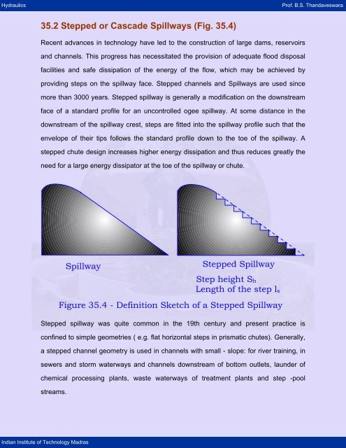
<strong>35.2</strong> <strong>Stepped</strong> <strong>or</strong> <strong>Cascade</strong> <strong>Spillways</strong> (Fig. 35.4)<br />
Recent advances in technology have led to the construction <strong>of</strong> large dams, reservoirs<br />
and channels. This progress has necessitated the provision <strong>of</strong> adequate flood disposal<br />
facilities and safe dissipation <strong>of</strong> the energy <strong>of</strong> the flow, which may be achieved by<br />
providing steps on the spillway face. <strong>Stepped</strong> channels and <strong>Spillways</strong> are used since<br />
m<strong>or</strong>e than 3000 years. <strong>Stepped</strong> spillway is generally a modification on the downstream<br />
face <strong>of</strong> a standard pr<strong>of</strong>ile f<strong>or</strong> an uncontrolled ogee spillway. At some distance in the<br />
downstream <strong>of</strong> the spillway crest, steps are fitted into the spillway pr<strong>of</strong>ile such that the<br />
envelope <strong>of</strong> their tips follows the standard pr<strong>of</strong>ile down to the toe <strong>of</strong> the spillway. A<br />
stepped chute design increases higher energy dissipation and thus reduces greatly the<br />
need f<strong>or</strong> a large energy dissipat<strong>or</strong> at the toe <strong>of</strong> the spillway <strong>or</strong> chute.<br />
Spillway<br />
<strong>Indian</strong> <strong>Institute</strong> <strong>of</strong> Technology Madras<br />
<strong>Stepped</strong> Spillway<br />
Step height Sh<br />
Length <strong>of</strong> the step ls<br />
Figure 35.4 - Definition Sketch <strong>of</strong> a <strong>Stepped</strong> Spillway<br />
<strong>Stepped</strong> spillway was quite common in the 19th century and present practice is<br />
confined to simple geometries ( e.g. flat h<strong>or</strong>izontal steps in prismatic chutes). Generally,<br />
a stepped channel geometry is used in channels with small - slope: f<strong>or</strong> river training, in<br />
sewers and st<strong>or</strong>m waterways and channels downstream <strong>of</strong> bottom outlets, launder <strong>of</strong><br />
chemical processing plants, waste waterways <strong>of</strong> treatment plants and step -pool<br />
streams.
Hydraulics Pr<strong>of</strong>. B.S. Thandaveswara<br />
Detailed investigation into its various elements started only about 1978 with the<br />
comprehensive lab<strong>or</strong>at<strong>or</strong>y tests by Essery and H<strong>or</strong>ner (1978).<br />
During the 19th century and early 20 th century, <strong>Stepped</strong> waste - waterways ( also<br />
called ' byewash' ) were commonly used to assist with energy dissipation <strong>of</strong> the flow<br />
(CHANSON 1995, "Hydraulic design <strong>of</strong> stepped <strong>Cascade</strong> channels, Weirs and<br />
Spillway", pergamon UK, 292 pages Jan 1995). Now a days stepped spillways are <strong>of</strong>ten<br />
associated with roller compacted concrete ( RCC ) dams.<br />
The stepped geometry is appropriate to the RCC placement techniques and enhances<br />
the rate <strong>of</strong> energy dissipation compared to a smooth chute design. A related application<br />
is the overtopping protection <strong>of</strong> embankments with RCC overlays ( e.g. ASCE Task<br />
F<strong>or</strong>ce Rep<strong>or</strong>t, 1994.<br />
Alternatives f<strong>or</strong> over topping protection <strong>of</strong> Dam - Task f<strong>or</strong>ce Commitee on over topping<br />
protection, 139 pages).<br />
<strong>35.2</strong>.1 Suitability<br />
Energy dissipation below hydraulic structures is accomplished generally by single -fall<br />
hydraulic jump type stilling basins, roller buckets <strong>or</strong> traject<strong>or</strong>y buckets. However, when<br />
the kinetic energy at the toe <strong>of</strong> the spillway would be high. The tail water depths in the<br />
river are <strong>of</strong>ten inadequate. Then first two devices, cannot be used as in the case <strong>of</strong> high<br />
head dams.<br />
In narrow curved g<strong>or</strong>ges consisting <strong>of</strong> fractured rocks, buckets cannot be used. In such<br />
situations, a system <strong>of</strong> cascading falls down the side <strong>of</strong> a valley, with a stilling basin in<br />
the downstream, can be used as an alternative spillway. <strong>Cascade</strong> spillways can be<br />
used f<strong>or</strong> any type <strong>of</strong> dam irrespective <strong>of</strong> the material <strong>of</strong> construction.<br />
The only disadvantage with stepped spillway is that at large discharges, as the jet is not<br />
aerated f<strong>or</strong> some distance downstream <strong>of</strong> the spillway, low pressure may occur and<br />
lead to cavitation damage.<br />
<strong>Indian</strong> <strong>Institute</strong> <strong>of</strong> Technology Madras
Hydraulics Pr<strong>of</strong>. B.S. Thandaveswara<br />
<strong>35.2</strong>.2 Physical Modelling <strong>of</strong> <strong>Stepped</strong> Spillway<br />
Free surface flows are commonly modelled using Froude similitude. The various flow<br />
elements,<br />
(1) the role <strong>of</strong> the steps in enhancing turbulent dissipation as well as their interaction<br />
with other adjacent steps and,<br />
(ii ) the effect <strong>of</strong> aerated flow make it difficult to model.<br />
<strong>35.2</strong>.3 Classification <strong>of</strong> Flow<br />
The concept <strong>of</strong> stepped spillway was used as early as 1892 - 1906 in New Croton dam.<br />
Lombardi and Marquenent were first to consider stepped spillway consisting <strong>of</strong> concrete<br />
drop spillway and intermediate erodible river reaches. The slopes <strong>of</strong> these reaches were<br />
such that a hydraulic jump occurred at the base <strong>of</strong> each drop. However, the<br />
experimental studies revealed three types <strong>of</strong> flows over a stepped spillway, namely,<br />
nappe flow, partial nappe flow (intermediate(transition)) and skimming flow.<br />
A stepped chute consists <strong>of</strong> a open channel with a series <strong>of</strong> drops in the invert. F<strong>or</strong> a<br />
given chute pr<strong>of</strong>ile, the flow patten may be either nappe flow at low flow rates, transition<br />
flow f<strong>or</strong> intermediate discharges <strong>or</strong> skimming flow at larger flow rates.<br />
Nappe Flow<br />
This type <strong>of</strong> flow occurs f<strong>or</strong> small discharges. The flow cascades over the steps, falls in<br />
a series <strong>of</strong> plunges from one step to another in a thin layer that clings to the face <strong>of</strong><br />
each step, with the energy dissipation occurring by breaking <strong>of</strong> the jet in the air, impact<br />
<strong>of</strong> jet on the step, mixing on the step, with <strong>or</strong> without the f<strong>or</strong>mation <strong>of</strong> a partial hydraulic<br />
jump on the step. The step height sh must be relatively large f<strong>or</strong> nappe flow. This<br />
situation may apply to relatively flat stepped channels <strong>or</strong> at low flow rates.<br />
The depths can be determined from the expressions,<br />
Following equations to be checked f<strong>or</strong> notations:<br />
<strong>Indian</strong> <strong>Institute</strong> <strong>of</strong> Technology Madras
Hydraulics Pr<strong>of</strong>. B.S. Thandaveswara<br />
<strong>Indian</strong> <strong>Institute</strong> <strong>of</strong> Technology Madras<br />
0.425<br />
y ⎛ 2<br />
1 q ⎞<br />
= 0.54 ⎜ ⎟<br />
(35.1)<br />
S 3<br />
h ⎜ gS<br />
⎟<br />
1 ⎝ h1<br />
⎠<br />
0.27<br />
y ⎛ 2<br />
1 q ⎞<br />
= 1.66 ⎜ ⎟<br />
(<strong>35.2</strong>)<br />
S 3<br />
h ⎜ gS<br />
⎟<br />
1 ⎝ h1<br />
⎠<br />
0.22<br />
yc<br />
⎛ q<br />
2 ⎞<br />
= ⎜ ⎟<br />
(35.3)<br />
S 3<br />
h ⎜ gS<br />
⎟<br />
1 ⎝ h1<br />
⎠<br />
However, the steps f<strong>or</strong> a nappe flow <strong>or</strong> plunge pool type <strong>of</strong> flow need to be relatively<br />
large. In otherw<strong>or</strong>ds, tread requires to be larger than the depth <strong>of</strong> flow. This requires<br />
downstream slope <strong>of</strong> dam face to be relatively flatter. Chanson observes that if slope <strong>of</strong><br />
downstream face is greater than 1 : 5, the nappe flow system becomes uneconomical<br />
except in case <strong>of</strong> embankment type structure <strong>or</strong> steep rivers.<br />
Partial Nappe Flow (Fig.35.5)<br />
In this type <strong>of</strong> flow, the nappe does not fully impinge on the step surface and it<br />
disperses with considerable turbulence. Flow is super - critical down the length <strong>of</strong> the<br />
spillway.<br />
yc<br />
yp<br />
yp<br />
Figure 35.5 - Partial nappe flow
Hydraulics Pr<strong>of</strong>. B.S. Thandaveswara<br />
F<strong>or</strong> a given step geometry, an increase in flow rate may lead to intermediate flow patten<br />
between nappe and skimming flow - the transition flow regime also called a partial<br />
nappe flow. The transition flow is characterised by a pool <strong>of</strong> circulating water and <strong>of</strong>ten<br />
accompanied by a very small air bubble (cavity), and significant water spray and the<br />
deflection <strong>of</strong> water jet immediately downstream <strong>of</strong> the stagnation point. Downstream <strong>of</strong><br />
the spray region, the supercritical flow decelerates upto the downstream step edge. The<br />
transition flow pattern exhibits significant longitudinal variations <strong>of</strong> the flow properties on<br />
each step. It does not present the coherent appearance <strong>of</strong> skimming flows.<br />
Skimming Flow (Fig. 35.6)<br />
In skimming flow regimes, the water flows down the stepped face as a coherent stream,<br />
skimming over the steps and cushioned by the recirculating fluid trapped between them.<br />
The external edges <strong>of</strong> the steps f<strong>or</strong>m a pseudobottom over which the flow skims.<br />
Beneath this, recirculating v<strong>or</strong>tices f<strong>or</strong>m and are sustained through the transmission <strong>of</strong><br />
shear stress from the water flowing past the edge <strong>of</strong> the steps. At the upstream end, the<br />
flow is transparent and has glossy appearance and no air entrainment takes place. After<br />
a few steps the flow is characterised by air entrainment similar to a self -aerated flow<br />
down a smooth invert spillway. In case <strong>of</strong> the skimming flow, at each step, whether air<br />
entrainment occurs <strong>or</strong> otherwise, a stable v<strong>or</strong>tex develops and the overlying flow moves<br />
down the spillway supp<strong>or</strong>ted by these v<strong>or</strong>tices, which behave as solid boundary f<strong>or</strong> the<br />
skimming flow, and the tips <strong>of</strong> the steps. There is a continous exchange <strong>of</strong> flow between<br />
top layer and v<strong>or</strong>tices f<strong>or</strong>med on steps. The flow rotates in the v<strong>or</strong>tex f<strong>or</strong> a brief period<br />
and then returns to the main flow to proceed on down the spillway face. Similarly, air<br />
bubbles penetrate and rotate with the v<strong>or</strong>tex flow, when aeration takes place.<br />
Transition from one type <strong>of</strong> flow to another is gradual and continuous, as a result both<br />
the nappe flow and the skimming flow, appear simultaneously in a certain range, one <strong>of</strong><br />
them on some steps and other on the remaining, both changing spatially and<br />
temp<strong>or</strong>arily.<br />
<strong>Indian</strong> <strong>Institute</strong> <strong>of</strong> Technology Madras
Hydraulics Pr<strong>of</strong>. B.S. Thandaveswara<br />
<strong>Indian</strong> <strong>Institute</strong> <strong>of</strong> Technology Madras<br />
sh<br />
Recirculating<br />
flow<br />
l<br />
yc<br />
V0<br />
Figure 35.6 - Fully developed skimming flow<br />
<strong>35.2</strong>.4 Transition from Crest to Initial Steps<br />
S<strong>or</strong>ensen found the free surface jet to be smooth down to the point <strong>of</strong> inception <strong>of</strong> air<br />
entrainment. This point <strong>of</strong> inception moves progressively upstream as the discharge<br />
decreases. However, f<strong>or</strong> very small discharge, the jet after striking the first step was<br />
redirected outward and skips several steps bef<strong>or</strong>e it strikes the spillway face again<br />
several steps further down. This could be overcome by introducing few smaller steps on<br />
upper reaches <strong>of</strong> the spillway.
Hydraulics Pr<strong>of</strong>. B.S. Thandaveswara<br />
<strong>35.2</strong>.5 Basic Equation f<strong>or</strong> Skimming Flow<br />
Consider a skimming flow in which dominant feature is the momentum exchange<br />
between the free stream and the cavity flow within the steps. Basic dimensional analysis<br />
yields ( Figure 35.6 ),<br />
<strong>Indian</strong> <strong>Institute</strong> <strong>of</strong> Technology Madras<br />
f 1 ( V ο, y ο, S h , ls<br />
, k s , g, θ ο,<br />
µ , ρ )= 0 (35.4)<br />
1<br />
f<strong>or</strong> h<strong>or</strong>izontal steps, θ = tan<br />
-1<br />
ο (S h / ls).<br />
1<br />
Using Buckingum pi- the<strong>or</strong>em equation can be written as<br />
⎡ V ρV<br />
y Sh<br />
1 ks<br />
⎤<br />
f 2<br />
⎢ ο , ο ο , , , θο ⎥ = 0 (35.5)<br />
⎢ gyο µ ls<br />
S<br />
⎣ h ⎥<br />
1 ⎦<br />
Mixing layer<br />
__<br />
V0<br />
δ<br />
sh<br />
y0<br />
Velocity Distribution<br />
Shear layer edges<br />
Cavity (bubble)<br />
Figure 35.7 - Hydrodynamic feature <strong>of</strong> a skimming flow<br />
While deriving the above equation the interaction <strong>of</strong> adjacent steps and the effect <strong>of</strong> air<br />
entrainment has not been taken into account. Hence, Froude number similitude alone<br />
cannot describe the complexity <strong>of</strong> stepped spillway flows completely.<br />
Chanson showed that Froude number has no effect on flow resistance and that<br />
Reynolds number might not have a substantial effect and that the f<strong>or</strong>m drag was related<br />
primarily to step cavity geometry. It was also rep<strong>or</strong>ted that in case <strong>of</strong> small scale models<br />
the developing flow regimes and flow resistance were not c<strong>or</strong>rectly reproduced.<br />
ls
Hydraulics Pr<strong>of</strong>. B.S. Thandaveswara<br />
<strong>35.2</strong>.6 Onset <strong>of</strong> Skimming Flow<br />
Onset <strong>of</strong> skimming flow occurs when the space between the water surface at the two<br />
consecutive edges <strong>of</strong> the steps is filled up with water, there by, creating a smooth<br />
surface <strong>of</strong> water parallel to the average slope <strong>of</strong> the spillway face - the condition very<br />
difficult to establish analytically. Theref<strong>or</strong>e, empirical equations have been proposed by<br />
many investigat<strong>or</strong>s f<strong>or</strong> the delineation <strong>of</strong> the skimming flow from nappe flow over<br />
stepped spillway.<br />
Essery and H<strong>or</strong>ner rep<strong>or</strong>ted that it is very difficult to distinguish between nappe and<br />
skimming flow f<strong>or</strong> flatter slopes having S /l < 04 . .<br />
<strong>Indian</strong> <strong>Institute</strong> <strong>of</strong> Technology Madras<br />
h1s Based on available data Rajaratnam found the skimming flow to occur f<strong>or</strong><br />
On the other hand, Stephenson introduced a term called Drop number,<br />
to distinguish between nappeflow [ D< 0.6 ] and skimming flow [ D > 0.6]<br />
y / S > 08 . .<br />
c h1<br />
⎡ 2 3<br />
D= q / gS ⎤<br />
⎣ h1<br />
⎦<br />
Peyras, et al. studied gabion dams consisting <strong>of</strong> four step element each 0.2 m high.<br />
It was found that the transition from nappe to skimming flow occurs f<strong>or</strong> a discharge <strong>of</strong><br />
approximately 1.5 m3 / s /m <strong>or</strong> at y/ S < 05 . while Degoutte found the onset <strong>of</strong><br />
c h1<br />
skimming flow on gabion steps to occur at y/ S = 074 . f<strong>or</strong> S /l = 033 . and at 0.62 f<strong>or</strong><br />
c h1<br />
h1s S /l = 10 . . Based on the available data, Chanson developed a regression equation<br />
h1s f<strong>or</strong> the onset <strong>of</strong> skimming flow, namely.<br />
In which k1 1 , F<br />
2 b<br />
Fb<br />
yc<br />
><br />
s<br />
h<br />
2/3<br />
b 1<br />
F k<br />
⎛ 2 3/2 cos α ⎞<br />
1+ 2F b<br />
b(k 1)<br />
⎜1− ⎜<br />
⎟<br />
k ⎟<br />
⎝ 1 ⎠<br />
1<br />
= + is the Froude number at the brink <strong>of</strong> the step and α b is the<br />
streamline angle with the h<strong>or</strong>izontal. This equation is applicable to the accelerated flow<br />
and may predict jet deflection at the first step <strong>of</strong> the cascade.
Hydraulics Pr<strong>of</strong>. B.S. Thandaveswara<br />
yc / sh<br />
1.40<br />
1.20<br />
1.00<br />
0.80<br />
0.60<br />
0.40<br />
0.20<br />
<strong>Indian</strong> <strong>Institute</strong> <strong>of</strong> Technology Madras<br />
Skimming Flow<br />
Nappe Flow<br />
0.00<br />
0 0.2 0.4 0.6 0.8 1 1.2<br />
Figure 35.8 - Onset <strong>of</strong> skimming / Nappe flow<br />
sh / ls<br />
<strong>35.2</strong>.7 Prediction <strong>of</strong> the flow regime<br />
Essery and H<strong>or</strong>ner<br />
PEYRAS et al.<br />
STEPHENSON<br />
BEITZ and LAWLESS<br />
MONTES<br />
KELLS<br />
RU et al. (1994)<br />
HORNER (1969)<br />
ELVIRO and MATEOS<br />
-20% Band<br />
+20% Band<br />
Transition fully / partially developed jump<br />
HORNER [NA1/NA2]<br />
The type <strong>of</strong> stepped flow regime is a function <strong>of</strong> the discharge and step geometry.<br />
Chanson has reanalysed a large number <strong>of</strong> experimental data related to change in flow<br />
regimes. Most <strong>of</strong> the data were obtained with flat h<strong>or</strong>izontal steps .<br />
Overall the result suggest that the upper limit <strong>of</strong> nappe flow may be approximated as:<br />
y<br />
c Sh<br />
=0.89 - 0.4 (35.6)<br />
Sh<br />
ls<br />
in which y c is the critical depth, S h is the step height, and<br />
ls<br />
is the step length. The above equation indicates the transition<br />
<strong>of</strong> flow from nappe to transition flow regime.<br />
While the lower limits <strong>of</strong> skimming flow may be estimated as.<br />
y<br />
c Sh<br />
= 1.2 −0.325<br />
(35.7)<br />
Sh<br />
ls<br />
on set <strong>of</strong> skimming flow is given<br />
by<br />
y<br />
c Sh<br />
> 1.057 −0.465<br />
Sh<br />
ls<br />
Further the equation 2 indicates the change <strong>of</strong> flow from<br />
transition flow to skimming flow region.<br />
Two issues must be clearly under stood.
Hydraulics Pr<strong>of</strong>. B.S. Thandaveswara<br />
Eqations 35.6 and 35.7 were fitted f<strong>or</strong> flat h<strong>or</strong>izontal steps with Sh/ls ranging from 0.05 to<br />
1.7 ( i.e 3.4°
Hydraulics Pr<strong>of</strong>. B.S. Thandaveswara<br />
<strong>Indian</strong> <strong>Institute</strong> <strong>of</strong> Technology Madras<br />
0.9<br />
0.8<br />
0.7<br />
<strong>35.2</strong>.8 Coefficient <strong>of</strong> Friction<br />
Rajaratnam<br />
Tatewar and Ingle<br />
Chanson<br />
0.6<br />
0.4 0.5 0.6 0.7 0.8 0.9<br />
sh1/l<br />
Figure 35.9 - Onset <strong>of</strong> skimming flow<br />
No<strong>or</strong>i studied in detail stepped steep open channel flows and rep<strong>or</strong>ted a drag coefficient<br />
<strong>of</strong> 0.19 f<strong>or</strong> ( S /l = 0.2 and<br />
h1s M = 62 [ { y + ( S / 2 ) f<strong>or</strong> S > 6 ] and, 0.17 f<strong>or</strong> ( S /l ) = 0.1 and M= 100 [ { y + ( S /<br />
2 ) f<strong>or</strong><br />
S h > 10 ].<br />
1<br />
h1<br />
h1<br />
h1s In this, the value <strong>of</strong> y can be estimated at any point on the spillway as,<br />
y =<br />
φ<br />
q<br />
[ 2g(z -H) ]<br />
in which z is the vertical distance below the crest measured to the water surface at the<br />
point where y is to be determined.<br />
The value <strong>of</strong> φ f<strong>or</strong> a stepped block was found to be considerably smaller than that f<strong>or</strong><br />
smooth spillway f<strong>or</strong> large value <strong>of</strong> (ls/ yc);<br />
0.5<br />
h1
Hydraulics Pr<strong>of</strong>. B.S. Thandaveswara<br />
S h is the length <strong>of</strong> the step) and slope <strong>of</strong> the spillway, and hence, a considerable<br />
1<br />
energy loss at the toe <strong>of</strong> the stepped spillway.<br />
Based on the avilable data, Rajaratnam suggested the following equation f<strong>or</strong> the<br />
variation <strong>of</strong> coefficient <strong>of</strong> friction, c f , f<strong>or</strong> aerated skimming flow.<br />
<strong>Indian</strong> <strong>Institute</strong> <strong>of</strong> Technology Madras<br />
3<br />
2y0gs0 f 2<br />
c = q<br />
The value <strong>of</strong> c f was found to be 0.18 as compared to 0.0065 f<strong>or</strong> smooth spillway, while<br />
Christodoulou (1993) found c f to vary from 0.076 to 0.89 and , c f being higher down<br />
the steps.<br />
Tozzi evaluated the friction fact<strong>or</strong> on stepped chutes <strong>of</strong> slope 1:2 ( V: H ) by analysing<br />
the energy loss <strong>of</strong> air flowing in a closed conduit with roughness elements designed to<br />
simulate the slope,<br />
The value <strong>of</strong> is found to be f = 0.09. It was noted that the value is overestimated if<br />
unif<strong>or</strong>mly aerated flow conditions are not attained. Matos and Quentela concluded that a<br />
value <strong>of</strong> f = 0.1 can be safely considered f<strong>or</strong> the preliminary hydraulic design <strong>of</strong> stepped<br />
spillway f<strong>or</strong> slopes around 1 : 0.75 ( V: H ), typical <strong>of</strong> concrete gravity dams.<br />
<strong>35.2</strong>.9 Energy Loss on <strong>Stepped</strong> Spillway<br />
When an overflow is smoothly directed to an outlet structure by the chute where a<br />
concentrated energy dissipation takes place, the cascade c<strong>or</strong>responds to a distributed<br />
dissipat<strong>or</strong>. Hence, the terminal structure has only smaller area <strong>of</strong> energy to dissipate,<br />
and would be significantly smaller. A quantitative comparison between the conventional<br />
system chute - stilling basin and the spillway cascade is shown in figures. The latter<br />
type is suited f<strong>or</strong> small and medium discharges and has recently gained some<br />
popularity with Roller Compacted Concrete dams.
Hydraulics Pr<strong>of</strong>. B.S. Thandaveswara<br />
RVF<br />
<strong>Indian</strong> <strong>Institute</strong> <strong>of</strong> Technology Madras<br />
GVF<br />
boundary layer<br />
Point <strong>of</strong><br />
inception<br />
Growth <strong>of</strong> boundary layer<br />
Energy Line<br />
PI<br />
DZ<br />
UAF<br />
T<br />
PHJ<br />
PI = Point <strong>of</strong> Inception<br />
RVF = Rapidly Varied Flow<br />
GVF = Gradually Varied Flow<br />
DZ = Developing Zone<br />
UAF = Unif<strong>or</strong>mily Aerated Flow Region<br />
PHJ = Pre-entrained Hydraulic Jump<br />
Skimming Flow<br />
A
Hydraulics Pr<strong>of</strong>. B.S. Thandaveswara<br />
The typical geometry <strong>of</strong> the stepped spillway with the standard crest geometry and<br />
increasing step height up to the point <strong>of</strong> tangency T are shown in the above figure.<br />
The free surface pr<strong>of</strong>ile is smooth upto crest inspite <strong>of</strong> the development <strong>of</strong> v<strong>or</strong>tex in<br />
each step. The transition to rough surface flow occurs beyond point A where the air<br />
entrainment is initiated. The hydraulic features <strong>of</strong> the cascade spillway as compared to<br />
chute flow are:<br />
<strong>Indian</strong> <strong>Institute</strong> <strong>of</strong> Technology Madras<br />
• the flow depth is much larger than in a chute due to the highly turbulent cascade<br />
flow, and higher sidewalls are required,<br />
• m<strong>or</strong>e air is entrained and the spray action may become an imp<strong>or</strong>tant issue.<br />
• abrasion can be a serious problem f<strong>or</strong> flows with sediment <strong>or</strong> with floating debris.<br />
In cascade spillways two flow types may occur as shown in Figure.<br />
• Nappe flow: is the flow from each step hits the next step as a falling jet;<br />
• Skimming flow: the flow remains coherent over the individual steps.<br />
• The onset <strong>of</strong> skimming flow occurs f<strong>or</strong> yc /sh > 0.8, where yc is the critical depth<br />
and sh is the height <strong>of</strong> the step. When unif<strong>or</strong>m cascade flow occurs in long<br />
channels, skimming flow dissipates m<strong>or</strong>e energy than nappeflow. However,<br />
nappe flow is m<strong>or</strong>e efficient f<strong>or</strong> a sh<strong>or</strong>t cascade than skimming flow (Chanson,<br />
1994) the energy dissipated hf relative to the drop height Hodepends on the drop<br />
Froude number and the slope <strong>of</strong> the spillway.<br />
Stephenson ( 1991 ) expressed the relative energy loss as<br />
∆H ⎛ 0.84 ⎞<br />
= F<br />
-1/3<br />
⎜ ο<br />
(1)<br />
H 0.25 ⎟<br />
0 ⎝θ⎠ in which ∆H is the energy loss over a height H0, F0 is the<br />
⎡ q ⎤<br />
Froude Number = ⎢ 3 ⎥<br />
⎣gH0 ⎦<br />
0.5<br />
, and θ is expressed in degrees in the above equation.<br />
The energy dissipated ∆H relative to the drop height H0 depends on the drop Froude<br />
3<br />
number Fo q ( gHo)<br />
= and θ slope <strong>of</strong> the spillway.
Hydraulics Pr<strong>of</strong>. B.S. Thandaveswara<br />
Acc<strong>or</strong>dingly, the effect <strong>of</strong> slope is small, where as the dam height has considerable<br />
influence on the head loss. Christodoulou (1993) studied the effect <strong>of</strong> number <strong>of</strong> steps N<br />
on the energy dissipation ∆ H / H0. He introduced the parameter hc= yc / ( Nsh ) with yc =<br />
(q 2 /g) 1 / 3 as critical depth sh as the step height and found f<strong>or</strong> hc < 0.25<br />
∆ H<br />
= exp( − 30 h<br />
2<br />
c ) (2)<br />
Hο<br />
By Increasing the number <strong>of</strong> steps the energy dissipation can be increased and hence<br />
the perf<strong>or</strong>mance <strong>of</strong> the stepped spillway.<br />
F<strong>or</strong> a long cascade, above 90% <strong>of</strong> mechanical energy is dissipated along the cascade<br />
and only a small P<strong>or</strong>tion <strong>of</strong> energy must be dissipated in the stilling basin.<br />
Acc<strong>or</strong>ding to Stephenson ( 1991 ) the efficiency <strong>of</strong> the cascade spillway depends mainly<br />
on its height and the specific discharge and marginally on the slope.<br />
The cascade flow may reach a state <strong>of</strong> nearly unif<strong>or</strong>m flow (subscript n) which may be<br />
approximated with ls , as step length ( Vischer and Hager. 1995).<br />
<strong>Indian</strong> <strong>Institute</strong> <strong>of</strong> Technology Madras<br />
h<br />
4 6 3 1/2<br />
n = 0.23 [ l s q / ( shg<br />
)] (3)<br />
Diez-Cascon et al. (1991) conducted experimental investigation on a cascade spillway<br />
<strong>of</strong> step size ls / sh = 0.75 and slope θ = 53°, followed by a h<strong>or</strong>izontal stilling basin . The<br />
sequent depth ratio varied with the approach Froude number F1 as<br />
Y r = 2.9 F<br />
1<br />
The resulting tailwater depth is higher than f<strong>or</strong> the classical hydraulic jump, however,<br />
the value F 1 f<strong>or</strong> cascade flow is much smaller. The above equation is valid f<strong>or</strong> unif<strong>or</strong>m<br />
approach flow. One may derive the following equation.<br />
2 /3<br />
F<br />
2 / 3 1/ 3<br />
n = 7. 3 ( h n / l s )<br />
and Y<br />
1 / 3<br />
r = 21.1 ( h n / l s ) (4)<br />
The sequent depth ratio varies slightly with the unif<strong>or</strong>m flow depth relative to the step<br />
height.
Hydraulics Pr<strong>of</strong>. B.S. Thandaveswara<br />
*<br />
Acc<strong>or</strong>ding to Chanson ( 1994) the onset <strong>of</strong> nappe flow occurs f<strong>or</strong> yc > yc<br />
where<br />
y<br />
*<br />
c<br />
sh<br />
= 1.057 − 0.465<br />
sh ls In the transitional regime between nappe and skimming flow hydraulic instability occurs<br />
which should be avoided to prevent the problems with vibration <strong>of</strong> structures.<br />
F<strong>or</strong> skimming flow, the resistance characteristics are governed by the distance between<br />
two adjacent step edges, protruding into the flow. Even though Chanson (1994)<br />
analysed the hydraulics <strong>of</strong> skimming flow, there is inadequate data to describe unif<strong>or</strong>m<br />
cascade flow. A basic investigation is needed to obtain further inf<strong>or</strong>mation.<br />
Though, it was clearly stated as early as 1970 that the adavantage <strong>of</strong> steps is to<br />
dissipate energy a little at a time but this is true only at low flow rates.<br />
Where as, the energy dissipation occurs due to jet breakup in the air, jet mixing on the<br />
step, with <strong>or</strong> with out the f<strong>or</strong>mation <strong>of</strong> a partial hydraulic jump on the steps in case <strong>of</strong><br />
nappe flow; the energy dissipation in skimming flow occurs due to the momentum<br />
transfer to the recirculating fluid. Hence, the methods required f<strong>or</strong> estimation <strong>of</strong> the<br />
energy loss need to be different f<strong>or</strong> the two types. In general, about 88% to 94 %<br />
reduction in kinetic energy was noted from the velocity measurements at the spillway<br />
toe without and with steps. F<strong>or</strong> isolated nappe flow, Peyras et al., presented an<br />
equation (see table) f<strong>or</strong> determining the energy loss below the stepped gabion<br />
<strong>Indian</strong> <strong>Institute</strong> <strong>of</strong> Technology Madras
Hydraulics Pr<strong>of</strong>. B.S. Thandaveswara<br />
Auth<strong>or</strong>s Remarks Energy loss equation<br />
Peyras et al.<br />
(1992)<br />
Isolated<br />
nappe<br />
⎛ 2<br />
q ⎞<br />
∆E = Ns h + 1.5 y c - ⎜ 2 ⎟<br />
2gy ⎟<br />
⎝ 1 ⎠<br />
Rajarathnam, skimming 88.89 % <strong>of</strong> self aerated flow<br />
1990 flow<br />
Tatewar and<br />
Ingle (1999)<br />
Relative<br />
loss (upper<br />
limit <strong>of</strong><br />
energy<br />
loss)<br />
∆ E 1<br />
=<br />
E0 2 ⎡ y<br />
1 1.25 C c<br />
⎤<br />
+ d ⎢ ⎥<br />
⎣H dam + Head over spillway ⎦<br />
Chamani and<br />
Rajarathnam<br />
Relative<br />
loss<br />
⎡ N−1 ⎡ yc<br />
⎤<br />
⎤<br />
⎢( 1− αf ) ⎢1+ 1.5 ( 1 αfi)<br />
E s<br />
⎥+<br />
∑ − ⎥<br />
∆ h i= 1<br />
= 1−⎢<br />
⎣ ⎦<br />
⎥<br />
E ⎢<br />
0 ⎡ y<br />
N 1.5 c ⎤ ⎥<br />
⎢ ⎢ +<br />
s<br />
⎥ ⎥<br />
⎢⎣ ⎣ h ⎦ ⎥⎦<br />
in which α is the prop<strong>or</strong>tion <strong>of</strong> energy loss per step a function<br />
Tatewar and<br />
Ingle (1966)<br />
<strong>Indian</strong> <strong>Institute</strong> <strong>of</strong> Technology Madras<br />
Regression<br />
analysis f<strong>or</strong><br />
α<br />
Chanson in terms <strong>of</strong><br />
friction<br />
fact<strong>or</strong> f<br />
f<br />
⎛y⎞ ⎛s⎞ <strong>of</strong> and<br />
f<br />
c h<br />
⎜ ⎟ ⎜ ⎟<br />
⎝sh ⎠ ⎝ ls<br />
⎠<br />
y s<br />
α f = -0.1169 - 0.8221 log + 0.0675 log θ - 0.5481 log<br />
s l<br />
E0E = 1 -<br />
E0<br />
c h<br />
h s<br />
1/3 − 2/3<br />
−<br />
⎛ f ⎞<br />
⎜ ⎟<br />
⎝8sin θ ⎠<br />
⎛ f ⎞<br />
cos θ + 0.5 ⎜ ⎟<br />
⎝8sin θ ⎠<br />
H<br />
15 + dam<br />
y<br />
It was found that actual dissipation could be 10 % m<strong>or</strong>e in case <strong>of</strong> gabions as compared<br />
to concrete steps due to fact<strong>or</strong>s like infiltration in to the gabions, difference in surface<br />
roughness and spillway slope. It was also found that their equation is valid within 10% in<br />
case <strong>of</strong> partial nappe flow.<br />
Rajaratnam, found the ratio <strong>of</strong> energy dissipation by skimming flow to the energy<br />
contained in the flow down a smooth spillway is about 89%. He has assumed that the<br />
flow is unif<strong>or</strong>m skimming flow which implies a high spillway,<br />
with many steps. The residual energy varies from 9 % to 12 % depending on the<br />
discharge. Christodoulou in 1993 studied the effect <strong>of</strong> number <strong>of</strong> steps on energy<br />
dissipation in case <strong>of</strong> skimming flow.<br />
c
Hydraulics Pr<strong>of</strong>. B.S. Thandaveswara<br />
Using his own data f<strong>or</strong><br />
<strong>Indian</strong> <strong>Institute</strong> <strong>of</strong> Technology Madras<br />
S h /l<br />
1 s = 0.7 and f<strong>or</strong> N = 15 (number <strong>of</strong> steps) as well as the<br />
avilable data f<strong>or</strong> hc < 25, where hc = ( yc / NSh ), he showed f<strong>or</strong> the same discharge the<br />
energy dissipation increases with the increase in the number <strong>of</strong> steps. The dissipation<br />
may be significantly less on moderately stepped spillway when compared to the unif<strong>or</strong>m<br />
flow on high spillway. As he has not consider the effect <strong>of</strong><br />
l s / S h and, the energy loss<br />
1<br />
by the steps in the curved p<strong>or</strong>tion is likely to be m<strong>or</strong>e, the results <strong>of</strong> Christodoulou is not<br />
applicable to prototype. Using the weir f<strong>or</strong>mula to express discharge over the spillway in<br />
terms <strong>of</strong> head over the spillway including velocity <strong>of</strong> approach head, Tatewar and Ingle<br />
derived a simplified expression f<strong>or</strong> energy loss (upper limit <strong>of</strong> energy dissipation) using<br />
the equation f<strong>or</strong> the discharge over the weir and is given by<br />
∆ E<br />
1<br />
=<br />
E0 9 2⎛<br />
y ⎞<br />
1+ C c<br />
d ⎜ ⎟<br />
8 ⎝Hdam + H ⎠<br />
Chamani and Rajaratnam established a relation f<strong>or</strong> the energy dissipation in jet flow.<br />
Tatewar and Ingle based on regression analysis fitted an equation f<strong>or</strong> the prop<strong>or</strong>tion <strong>of</strong><br />
energy per step f<strong>or</strong> the range <strong>of</strong> θ from 5° to 20° S<br />
h<br />
/ l<br />
1<br />
y<br />
( c ) from 0.05 to 0.833.<br />
S<br />
h<br />
1<br />
s<br />
from 0.421 to 0.842 and<br />
They concluded that energy dissipation is m<strong>or</strong>e in case <strong>of</strong> inclined steps and α f<br />
increases marginally f<strong>or</strong> steeper slope and that the increase <strong>of</strong> α<br />
f<br />
is comparatively<br />
larger f<strong>or</strong> flatter slopes.
Hydraulics Pr<strong>of</strong>. B.S. Thandaveswara<br />
X<br />
<strong>Indian</strong> <strong>Institute</strong> <strong>of</strong> Technology Madras<br />
1.00<br />
0.90<br />
0.80<br />
0.70<br />
0.60<br />
0.50<br />
0.40<br />
0.30<br />
θ = 0 0<br />
H<strong>or</strong>izontal steps<br />
θ = 10 0 θ = 5 0<br />
θ = 20 0<br />
θ = 15 0 }Inclined steps<br />
0.20<br />
0.15<br />
0.05 0.1<br />
yc/sh1<br />
0.5<br />
<strong>35.2</strong>.10 Effect <strong>of</strong> Air Entrainment<br />
Variation <strong>of</strong> X with yc/sh1<br />
F<strong>or</strong> higher discharges the point <strong>of</strong> inception <strong>of</strong> air entrainment occurs past the end <strong>of</strong><br />
the spillway section and move progressively up as the discharge decreases.<br />
Typically, the depth decreases from the crest inception point, beyond which, owing to<br />
the bulking <strong>of</strong> the flow, the depth continuously<br />
increases towards the spillway toe. At very low Reynolds number, the nappe does not<br />
break and energy loss is affected.<br />
Aeration <strong>of</strong> cascades<br />
The Quality <strong>of</strong> waters <strong>of</strong> rivers, streams, creeks etc is <strong>of</strong>ten expressed in terms <strong>of</strong> the<br />
dissolved oxygen content ( DOC). Low dissolved oxygen value <strong>of</strong>ten does not allow the<br />
development as well may cause the death <strong>of</strong> aquatic life f<strong>or</strong>ms and indicates some f<strong>or</strong>m<br />
<strong>of</strong> pollution associated with excessive waste water inflows. In natural streams, obtain<br />
the DOC from the aeration <strong>of</strong> the free surface.
Hydraulics Pr<strong>of</strong>. B.S. Thandaveswara<br />
<strong>Stepped</strong> cascades are characterised by a large amount <strong>of</strong> self aeration and it may be<br />
used to reoxygenate depleted waters. In rivers, artificial stepped cascades and weirs<br />
have been built to enhance the DOC <strong>of</strong> polluted <strong>or</strong> eutrophic streams.<br />
<strong>Stepped</strong> cascades are also built in the downstream reach <strong>of</strong> large dams to re-oxygenate<br />
water.<br />
Example: Labyrinth weir crest length <strong>of</strong> 640 m, single drop 2.3 m, design discharge 14<br />
to 68 m 3 /s at South Houlston weir, USA and the two-step labyrinth drop structure (2<br />
drops <strong>of</strong> 2 m height and design discharge <strong>of</strong> 110 m 3 /s) <strong>of</strong> 640 m buit by the French<br />
Electricity Commission downstream <strong>of</strong> the Petit -Saut Dam ( the Petit-Saut Dam is a<br />
RCC construction) installed with an overflow stepped spillway. The downstream<br />
stepped cascade is designed to re- oxygenete the tailrace waters <strong>of</strong> power station (<br />
depleted in oxygen ). Further, there is a series <strong>of</strong> five aeration cascades built along the<br />
Calumet waterway in Chicago. The waterfalls are designed to re-oxygenate the polluted<br />
canal and combine flow aeration and aesthetics to create recreation parks.<br />
<strong>Stepped</strong> cascades could be used to reduce the dissolved nitrogen content also.<br />
In the treatment <strong>of</strong> drinking water, cascade aeration is used to remove dissolved gases (<br />
e.g. chl<strong>or</strong>ine).<br />
<strong>35.2</strong>.11 Air entrainment in Nappe Flow Regime<br />
Typical air concentration pr<strong>of</strong>iles based on the experimental investigation by Chanson<br />
and Toombes are shown in the figure.<br />
<strong>Indian</strong> <strong>Institute</strong> <strong>of</strong> Technology Madras
Hydraulics Pr<strong>of</strong>. B.S. Thandaveswara<br />
Air Cavity<br />
<strong>Indian</strong> <strong>Institute</strong> <strong>of</strong> Technology Madras<br />
Impact Point<br />
Spray Rebound Reattachment<br />
90 % 50 %<br />
Longitudinal Variation <strong>of</strong> Air Concentration (isocons) along the nappe<br />
Centre line <strong>of</strong> Step 2 qw = 0.150 m 2 /s after Chanson and Toombes,<br />
June - 1997<br />
The un-ventilated air cavity, the impact point and the spray region are also indicated.<br />
The main features <strong>of</strong> the air - water flow on step f<strong>or</strong> q = 0.15 m 2 s -1 are:<br />
• the large air-cavity beneath the nappe,<br />
• the sidewall standing waves and the spray ( i.e. rebounding waters ),<br />
• the large amount <strong>of</strong> flow aeration in the spary region,<br />
• the de- trainment at the spray re-attachment, and<br />
• the substantial free-surface aeration at the end <strong>of</strong> the step ( i.e. C = 19% )<br />
The flow patterns <strong>of</strong> the air - water flow on a down stream step : f<strong>or</strong> the same flow rate<br />
at the cascade ( step No.9). (Sh = 0.143, ls = 2.4 m, θ = 3.4°, 10 steps over 25 m long<br />
flume <strong>of</strong> 0.5 m width. In the absence <strong>of</strong> steps θ = 4.0 °).<br />
• in the absence <strong>of</strong> ventilation the air cavity had disappeared completely and<br />
recirculating water occupies the space beneath the nappe,<br />
• the introduction <strong>of</strong> a splitter ( into the nappe ) ventilates the nappe and induces<br />
the f<strong>or</strong>mation <strong>of</strong> a sizeable air cavity; as a result the nappe traject<strong>or</strong>y increases,<br />
• the spray region is imp<strong>or</strong>tant,<br />
• the amount <strong>of</strong> entrained air is basically identical at the upstream and downstream<br />
ends <strong>of</strong> the step ( i.e. C = 17% to 19%); the mean air content is maximum at the<br />
downstream <strong>of</strong> the nappe impact ( in the spray region ) and minimum at the<br />
downstream end <strong>of</strong> the step . An interesting difference is the presence <strong>of</strong> a small<br />
bubble (cavity) between the nappe and the re - circulating water . The
Hydraulics Pr<strong>of</strong>. B.S. Thandaveswara<br />
<strong>Indian</strong> <strong>Institute</strong> <strong>of</strong> Technology Madras<br />
introduction <strong>of</strong> a splitter helps in occurance <strong>of</strong> larger air cavity and enlarges the<br />
nappe traject<strong>or</strong>y.<br />
In comparison the mean air content at the downstream end <strong>of</strong> the smooth chute was<br />
about 0.08 and the maximum mean air concentration was about 0.12 at a section<br />
located 4 m downstream.<br />
Overall the stepped chute flow is significantly has higher aeration than the smooth chute<br />
flow f<strong>or</strong> the same flow rate. The air - water flow with the stepped channel is three -<br />
dimensional in nature unlike the smooth chute flow which is two - dimensional.<br />
<strong>35.2</strong>.12 Air Entrainment in Skimming Flows<br />
Modern concrete stepped spillways operate in a skimming flow regime. at the upstream<br />
end, the free surface is clear and transparent.<br />
However, a turbulent boundary layer develops along the chute invert.<br />
When the outer edge <strong>of</strong> the boundary layer emerges to the free surface, air entrainment<br />
commences.<br />
The distance to the inception point <strong>of</strong> air entrainment and the flow depth at inception are<br />
c<strong>or</strong>related by :<br />
The location where free surface aeration occurs is called the inception point <strong>of</strong> air<br />
entrainment. Its characteristics are the distance Li from the crest<br />
(measured along the invert) and the flow depth yi measured n<strong>or</strong>mal to the channel<br />
invert.<br />
Model and prototype data were re - analysed by Chanson in 1994.<br />
The dimensionless distance Li/ ks and depth yi /ks are plotted as functions <strong>of</strong> the<br />
dimensionless discharge.
Hydraulics Pr<strong>of</strong>. B.S. Thandaveswara<br />
k s is the step depth per unit width ( n<strong>or</strong>mal to the flow direction ), s h is the step height.<br />
empirical c<strong>or</strong>relations f<strong>or</strong> stepped chutes:<br />
- The dimensionless distance from crest L<br />
i<br />
/ Ks and flow depth<br />
y I<br />
( )<br />
<strong>Indian</strong> <strong>Institute</strong> <strong>of</strong> Technology Madras<br />
I<br />
s<br />
s<br />
/ k s increase with increasing dimensionless discharge F * =<br />
( )<br />
k s can be written as s h cos θ<br />
Thus F * =<br />
qw<br />
g sin θ k<br />
3<br />
L<br />
k<br />
( )<br />
0.0796<br />
( ) ( )<br />
= 9.719 sin θ F<br />
yI 0.4034<br />
=<br />
k sin θ<br />
0.04<br />
( F )<br />
*<br />
0.592<br />
s<br />
*<br />
0.713<br />
q<br />
w<br />
( )<br />
g sin θ s cos θ<br />
h<br />
3
Hydraulics Pr<strong>of</strong>. B.S. Thandaveswara<br />
LI / ks<br />
<strong>Indian</strong> <strong>Institute</strong> <strong>of</strong> Technology Madras<br />
y<br />
___ I<br />
ks<br />
1000<br />
500<br />
100<br />
50<br />
20<br />
10<br />
5<br />
2<br />
1<br />
10.00<br />
1.00<br />
0.10<br />
Trigomil dam<br />
___ LI<br />
ks = 9.719(sin ) 0.0796 (F*) 0.713<br />
θ<br />
Inception on smaller steps<br />
1.00 10.00 100.00<br />
1.00 10.00 100.00<br />
F<br />
*<br />
BaCaRa [1:10] (53 deg.)<br />
BEITZ and LAWLESS (50 deg.)<br />
BINDO (51 deg.)<br />
FRIZELL (27 deg.)<br />
HORNER (36.4 deg.)<br />
SORENSEN (52 deg.)<br />
TOZZI (53.1 deg.)<br />
ZHOU (51.3 deg.)<br />
Given equation f<strong>or</strong> 52 deg.<br />
Trigomil (51.3 deg.)<br />
PROTOTYPE<br />
N<strong>or</strong>malised Inception length as a function <strong>of</strong> dimensionless discharge<br />
after (Chanson and Toombes)<br />
___ yI<br />
ks = _______ 0.4034<br />
0.04 (sin θ)<br />
(F*) 0.592<br />
BaCaRa [1/10 \ 53 deg. ]<br />
BINDO (51 deg.)<br />
FRIZELL (27 deg.)<br />
SORENSEN (52 deg.)<br />
HORNER (36.4 deg.)<br />
TOZZI (53.1 deg.)<br />
ZHOU (51.3 deg.)<br />
Given equation (52 deg.)<br />
N<strong>or</strong>malised Inception depth (y ) as a function <strong>of</strong> dimensionless discharge<br />
after (Chanson and Toombes) I<br />
F *<br />
boundary layer growth rate is grater on stepped channels than on smooth chutes.<br />
Chanson in 1995 based on the reanalysed data, concluded that the experimental results<br />
are basically independent <strong>of</strong> the type <strong>of</strong> crest pr<strong>of</strong>ile.<br />
The re- analysed data included the types <strong>of</strong> crest pr<strong>of</strong>ile were included smooth ogee<br />
crest pr<strong>of</strong>iles follows by stepped chute ( with <strong>or</strong> without smaller first steps) and broad -<br />
crests followed by stepped chute.
Hydraulics Pr<strong>of</strong>. B.S. Thandaveswara<br />
Above Equations may be used f<strong>or</strong> estimating Li and yi. It may be noted that one<br />
prototype observation (Trigomil dam) fills the equation 1.<br />
<strong>35.2</strong>.13 Aeration in Fully - Developed Skimming Flow<br />
Downstream <strong>of</strong> the inception point <strong>of</strong> air entrainment, the flow becomes fully -developed<br />
and a layer containing a mixture <strong>of</strong> both air and water extends gradually through the<br />
fluid. Far downstream the flow becomes unif<strong>or</strong>mly aerated. This region is defined as the<br />
unif<strong>or</strong>m equilibrium flow region. The air concentration pr<strong>of</strong>iles are compared with a<br />
simple diffusion model by CHANSON 1995 and validated with prototype and model<br />
smooth - chute data . The following equation describes the air concentration distribution.<br />
2 ⎛ y ⎞<br />
C= 1−tanh ⎜K′ −<br />
⎜<br />
⎟<br />
2 D ′ y90 ⎟<br />
⎝ ⎠<br />
in which C is the air concentration, D' is a dimensionless turbulent diffusivity and K ' is<br />
constant <strong>of</strong> integration. D' and K' are functions <strong>of</strong> the mean air concentration C , y90 is<br />
the distance from bed at which 90% air concentration occurs.<br />
y<br />
__<br />
y90<br />
0.8<br />
0.6<br />
0.4<br />
0.2<br />
<strong>Indian</strong> <strong>Institute</strong> <strong>of</strong> Technology Madras<br />
1<br />
Measurements at Brushes Clough dam spillway (BAKER 1994) -<br />
Inclined downward steps (Sh = 0.19 m, is δ = - 5.6 deg.), θ = 18.4 degrees<br />
after BAKER (1994)<br />
Brushes Clough dam spillway<br />
0<br />
0 0.2 0.4 0.6 0.8 1<br />
Air concentration 'C'<br />
__<br />
C = 0.235 - Step 50<br />
__<br />
C = 0.178 - Step 30<br />
__<br />
C = 0.15 - Step 10<br />
__<br />
C = 0.20 - Step 73<br />
__<br />
The<strong>or</strong>y: C = 0.15<br />
__<br />
The<strong>or</strong>y: C = 0.235
Hydraulics Pr<strong>of</strong>. B.S. Thandaveswara<br />
y<br />
__<br />
y90<br />
0.8<br />
0.6<br />
0.4<br />
0.2<br />
<strong>Indian</strong> <strong>Institute</strong> <strong>of</strong> Technology Madras<br />
1<br />
0<br />
0 0.2 0.4 0.6 0.8 1<br />
Air concentration 'C'<br />
after RUFF AND FRIZELL (1994)<br />
(qw = 2.6 m 2 /s, θ =26.6 , inclined downward steps, Sh = 0.154 m )<br />
x is the distance<br />
__<br />
x = 14.8 m - C = 0.25<br />
__<br />
x = 13.8 m - C = 0.31<br />
__<br />
x = 26.8 m - C = 0.33<br />
__<br />
The<strong>or</strong>y: C = 0.25<br />
__<br />
The<strong>or</strong>y: C = 0.33<br />
Air concentration distribution in prototype observation after Baker and Ruff and Frizell (Chanson 1994)<br />
Table: Variation <strong>of</strong> the turbulent diffusivity and constant <strong>of</strong> integration with C .<br />
C<br />
( 1 )<br />
D'<br />
( 2 )<br />
K'<br />
( 3 )<br />
0.01 0.007 68.70<br />
0.05 0.037 14.00<br />
0.10 0.073 7.16<br />
0.15 0.110 4.88<br />
0.20 0.146 3.74<br />
0.30 0.223 2.57<br />
0.40 0.311 1.93<br />
0.50 0.423 1.51<br />
0.60 0.587 1.18<br />
0.70 0.878 0.90<br />
y90<br />
1<br />
C = ∫ C dy<br />
y90 0<br />
The analysis <strong>of</strong> model and prototype data showed that the air concentration pr<strong>of</strong>iles in<br />
skimming flows down a stepped chute have similar shape as those in smooth chute<br />
flows. Further the observed values <strong>of</strong> mean air concentration over stepped chute flow<br />
are very nearly same as the mean air concentration <strong>of</strong> the fully developed flow over<br />
smooth chutes : i.e., ( C) = 27% and 36% respectively f<strong>or</strong> = 18.4<br />
e o and 26.6 o .<br />
The data <strong>of</strong> Baker (1994) yielded C ranging between 15% and 23% with 18.4o slope<br />
and the data <strong>of</strong> Ruff and Frizell indicate C <strong>of</strong> 33% at the end <strong>of</strong> the 26.6 o slope channel.<br />
0
Hydraulics Pr<strong>of</strong>. B.S. Thandaveswara<br />
Free-surface aeration causes the bulkage <strong>of</strong> the flow and thus reducing the risks <strong>of</strong><br />
cavitation damage and enhanaces the air -water gas transfer (e.g. re- oxygenation <strong>of</strong><br />
the water). Futher, the presence <strong>of</strong> air nearer to the bed induces a reduction <strong>of</strong> drag and<br />
results in decrease in friction fact<strong>or</strong> . The drag reduction effect and the associated<br />
reduction in flow resistance may have a significant impact on the rate <strong>of</strong> energy<br />
dissipation on stepped spillway. The above analysis [ <strong>of</strong> energy dissipation ] by chanson<br />
neglects the effects <strong>of</strong> air entrainment. The friction fact<strong>or</strong> and the energy dissipation are<br />
affected significantly by the rate <strong>of</strong> free- surface aeration. The effects <strong>of</strong> air entrainment<br />
on the residual energy cannot be neglected f<strong>or</strong> [ channel ] slope larger than 30 degrees<br />
" and " the residual energy is strongly underestimated if the effect <strong>of</strong> air entrainment is<br />
neglected. It is most imp<strong>or</strong>tant that design engineers to take into account aeration <strong>of</strong><br />
flow to estimate the residual enegy and to dimension stilling basins downstream <strong>of</strong><br />
stepped chutes".<br />
<strong>35.2</strong>.14 Rapidly Varied Flow at the Inception Point<br />
The flow properties rapidly vary next to and immediately downstream <strong>of</strong> the inception<br />
point obervations suggest that some air is entrapped in the step cavity (ies).<br />
Immediately upstream the flow is extremely turbulent and the free surface is oscillating.<br />
At irregular time intervals, a water jet impinges on the h<strong>or</strong>izontal step face and air is<br />
trapped in the step cavity. An instant later, a rapid unsteady flow bulking is observed<br />
downstream. Velocity measurements indicate that, immediately upstream <strong>of</strong> the<br />
inception point, the turbulent velocity fluctuations are large, with dimensionless<br />
fluctuations u' / V <strong>of</strong> about 15 - 18 % and n<strong>or</strong>mal longitudinal and lateral components <strong>of</strong><br />
turbulent velocity, respectively. Observed values <strong>of</strong> u' = 0.14 m /s next to the free<br />
surface are large enough to initate air bubble entraiment. Immediately downstream <strong>of</strong><br />
the inception point, time-averaged air concentration data showed an increased aeration.<br />
F<strong>or</strong> example, increase in mean air concentration ∆ C = 25% along a distance ∆ x = 6.5 yc<br />
down a 30 o slope f<strong>or</strong> yc / sh = 5.2 ; an increase in mean air concentration ∆ C = 55 % in<br />
18 step heights down a 53 o slope f<strong>or</strong> yc / sh < 2 ; an increase in mean air concentration<br />
<strong>Indian</strong> <strong>Institute</strong> <strong>of</strong> Technology Madras
Hydraulics Pr<strong>of</strong>. B.S. Thandaveswara<br />
∆ C = 32% in 2 step heights down a 22 o slope f<strong>or</strong> yc / sh = 1.1, (where ∆ C is the mean<br />
air concentration).<br />
<strong>Indian</strong> <strong>Institute</strong> <strong>of</strong> Technology Madras<br />
Table : Increase in Mean Air Concentration Over <strong>Stepped</strong> Spillway<br />
Increase in<br />
concentration<br />
∆ I Bed slope S0<br />
(in degree)<br />
c<br />
Remarks<br />
∆ C%<br />
h<br />
25 6.5 yc 30 5.2<br />
55 * 53 < 2.0 * Over 18 steps<br />
32 * 22 1.1 Over 2 steps<br />
heights<br />
Reference<br />
1. BaCaRa, "Etude de la dissipation d' energie sur les evacuateurs a marches", (study<br />
<strong>of</strong> the energy dissipation on stepped spillways) Rapp<strong>or</strong>t d' Essais, Project National<br />
BaCaRa, CEMAGREF-SCP, Aix -en-provence, France, October 1991, 111 pages.<br />
2. BaCaRa. "Roller compacted concrete: RCC f<strong>or</strong> dams. "Presses de l' Ecole Nationale<br />
des Ponts et Chausse'es, Paris, 1997.<br />
3. Baker, R. "Brushes clough wedge block spillway - progress rep<strong>or</strong>t no. 3" SCEL Proj.<br />
Rewp. No. SJ542-4, University <strong>of</strong> Saf<strong>or</strong>d, U.K, 1994.<br />
4. Boes R.M, "Physical model study on two - phase cascade flow" , Proc 28th IAHR<br />
Congress, Graz, Austria, Session S1, 6 pages, 1991.<br />
5. Chamani, M.R., and Rajaratnam N. "characteristics <strong>of</strong> skimming flow over stepped<br />
spillways". J. Hydraulic Engineering, ASCE, 125 (5), 1999, 500 - 510. Discussion by<br />
Robert M. Boes; Chanson H; J<strong>or</strong>ge Matos; Ohtsu I, Yasuda Y and Takahashi; Tatewar<br />
S.P, Ingle R.N, P<strong>or</strong>ey P.D and closure, ibid, November 2000, page 860 - 873.<br />
6. Chanson H and Toombes Luke "Flow aeration at stepped cascades", Research<br />
rep<strong>or</strong>t number CE155, Department <strong>of</strong> Civil Engineering, Research Rep<strong>or</strong>t series,<br />
University <strong>of</strong> Queensland, June 1997.<br />
7. Chanson, H. "stepped spillway flows and air entrainment" Can. J. Civil Engineering,<br />
Ottawa, 20 (3), 1993, 422 - 435.<br />
y<br />
s
Hydraulics Pr<strong>of</strong>. B.S. Thandaveswara<br />
8. Chanson, H. "Discussion <strong>of</strong> model study <strong>of</strong> a roller compacted concrete spillway", J.<br />
Hydraulic Enginnering, ASCE, 123 (10), 1997b, 931 - 933.<br />
9. Chanson, H. "Hydraulics <strong>of</strong> Nappe flow regime above <strong>Stepped</strong> chutes and <strong>Spillways</strong>",<br />
Aust. Civil Engineering Trans., I.E. Aust., Vol. CE36, No. 1, Jan., 1994, pp.69-76.<br />
10. Chanson, H. "Hydraulic Design <strong>of</strong> <strong>Stepped</strong> cascades, Channels, Weirs and<br />
<strong>Spillways</strong>", Pergamon, Oxf<strong>or</strong>d, UK, Jan., 292 pages, 1995 .<br />
11. Chanson, H. "Air Bubble Diffusion in super critical open channel flow, Proc. 12th<br />
Australasian Fluid Mechanics Conference AFMC, Sydney Australia, R.W. Bilger Ed.,<br />
Vol. 2, 1995 , pp. 707 - 710.<br />
12. Chanson, H. " Prediction <strong>of</strong> the transition nappe / skimming flow on a stepped<br />
channel", Jl <strong>of</strong> Hydraulic Res., IAHR, Vol. 34, No. 3, 1996, pp. 421 - 429.<br />
13. Chanson, H. "Air bubble entrainment in free surface turbulent shear flows",<br />
Academic Press, London, UK, 1997, 401 pages.<br />
14. Chanson, H., and Whitm<strong>or</strong>e, R.L. "Investigation <strong>of</strong> the gold creek dam spillway,<br />
Australia. "Research Rep<strong>or</strong>t No. CE153, Department <strong>of</strong> Civil Engineering, University <strong>of</strong><br />
Queensland, Australia, 1996, 60 pages.<br />
15. Chanson H. "<strong>Stepped</strong> <strong>Spillways</strong> Parts 1 and 2", Journal <strong>of</strong> Physcial Science and<br />
Engineering Periodical, TA1 17526, Volume 5, No. 4, December 1997, Engineering<br />
update, technical paper number 10, page no. 7 to 12 and Journal <strong>of</strong> Physcial Science<br />
and Engineering Periodical, TA1 17256, Volume 6, No. 1, January - March 1998,<br />
Engineering update, Technical paper No. 2, page no. 9 to 14.<br />
16. Ge<strong>of</strong>frey G.S. Pegram, Andrew K. Officer and Samule R. Mottram, "Hydraulics <strong>of</strong><br />
skimming flow on Modeled <strong>Stepped</strong> <strong>Spillways</strong>", Journal <strong>of</strong> Hydraulic Engineering, May<br />
1999, Volume 125, No. 5, Paper 3557, Discussion by Robert M. Boes; J<strong>or</strong>ge Matos;<br />
Ohtsu I, Yasuda Y and Takahashi M; Tatewar S.P, Ingle R.N, P<strong>or</strong>ey P.D; ibid, and<br />
closure December 2000, page 947 - 953.<br />
17. Goubet, A. "Evacuateurs de Crues en Marches d' Escalier" (stepped spillways) La<br />
Houille Blanche, No. 2/3, pp. 247 - 248 , 1992.<br />
18. Hans - Erwin Min<strong>or</strong> and Willi Hager edit<strong>or</strong>s "Hydraulic <strong>of</strong> <strong>Stepped</strong> <strong>Spillways</strong>",<br />
Balkema, Rotterdam, The Netherlands, 2000; 201 pages.<br />
<strong>Indian</strong> <strong>Institute</strong> <strong>of</strong> Technology Madras
Hydraulics Pr<strong>of</strong>. B.S. Thandaveswara<br />
19. Houston, K.L. "Hydraulic Model Studies <strong>of</strong> Upper Stillwater Dam stepped Spillway<br />
and Outlet w<strong>or</strong>ks". Rep<strong>or</strong>t No. REC - ERC - 87 - 6, US Bureau <strong>of</strong> Reclamation, Denver<br />
Co, USA, 1987.<br />
20. Ruff. J.F. and Frizell, K.H, "Air concentration measurements in highly turbulent flow<br />
on a steeply sloping chute", Proceeding Hydraulic Engineering Conference, ASCE, New<br />
Y<strong>or</strong>k, Vol. 2, 999 - 1003.<br />
21. Stephenson, D. "Energy dissipation down stepped spillways" Water Power and Dam<br />
construction, September, 27 - 30, 1991.<br />
22. Tatewar S.P. Ingle R.N., Nappe Flow on Inclined <strong>Stepped</strong> <strong>Spillways</strong>, Journal <strong>of</strong> The<br />
Institution <strong>of</strong> Engineers (India), Volume - 79, Page- 175 - 179, Feb. 1999.<br />
23. Tatewar S.P., and Ingle R.N, Resistance to skimming flow over stepped spillway,<br />
Proceeding International Seminar on Civil Engineering Practices in 21st Century,<br />
Ro<strong>or</strong>kee, India, 1039 - 1048.<br />
24. Tozzi, M.J. "Residual energy in stepped spillways. "International water Power and<br />
Dam construction, 1994, 46 (5), 32 - 34.<br />
25. Virender Kumar, <strong>Stepped</strong> Spillway - a State <strong>of</strong> the art, Journal <strong>of</strong> The Institution <strong>of</strong><br />
Engineers (India), Volume - 82, Page- 217 - 223, Feb. 2002.<br />
26. Vischer D.L. and Hager W.H. "Dam Hydraulics", John Wiley and Sons, 1997.<br />
27. Yildiz, D., and Kas, I, "Hydraulic perf<strong>or</strong>mance <strong>of</strong> stepped chute spillways",<br />
Hydropower and Dams, 1998, 5 (4), 64 - 70.<br />
<strong>Indian</strong> <strong>Institute</strong> <strong>of</strong> Technology Madras