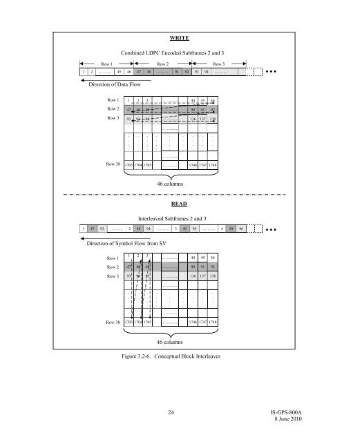
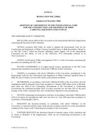
WRITECombined LDPC Encoded Subframes 2 and 3Row 1 Row 2 Row 31 2 ………. 45 46 47 48 ………. 91 92 93 94 ………. Direction of Data FlowRow 1Row 2Row 3Row 381 2 3 ……......... 44 45 4647 48 49 ................. 90 91 9293 94 95 ……......... 136 137 138................…….............…….........1703 1704 1705 ……......... 1746 1747 1748................46 columnsREADInterleaved Subframes 2 and 31 47 93 ………. 2 48 94 ………. 3 49 95 ………. 4 50 96 Direction of Symbol Flow from SVRow 11 2 3……......... 44 45 46Row 2Row 347 48 49 ................. 90 91 9293 94 95 ……......... 136 137 138…….............................................…….........Row 381703 1704 1705 ……......... 1746 1747 174846 columnsFigure 3.2-6. Conceptual Block Interleaver24 <strong>IS</strong>-<strong>GPS</strong>-<strong>800A</strong>8 June 2010
3.3 Signal ModulationThe signals modulated on the L1 RF carrier include C/A, P(Y), M, and L1C, which consists of two components:L1C P and L1C D . The modulation used is binary offset carrier (BOC) as described in reference document [2]. Themodulation is essentially shaped BPSK where a subcarrier is used to shape the spectrum.The bitstream of the L1C P signal is constructed by modulo-2 addition of L1C P -code and L1C O -code. The overlaycode, L1C O , is described in section 3.2.2.1.2. The PRN ranging codes, L1C P and L1C D , are described in section3.2.2.1.1. The bitstream of L1C D is constructed by modulo-2 addition of L1C D -code and the L1C message symboltrain, D L1C (t). The timing relationship of L1C signal components is described in Figure 3.3-1.The bitstream of the L1C D signal is modulated on L1 carrier frequency using BOC (1, 1) modulation, with asubcarrier frequency of 1.023 MHz and a chipping rate of 1.023 Mbps. Each bit of the bitstream is applied to aBOC (1,1) spreading symbol consisting of one cycle of a 1.023 MHz squarewave, defined as binary 10 (1= positivebinary bit value, see Figure 3.3-2a) with total duration 1/1.023 microseconds. The BOC (1,1) spreading symbols aredefined using sine-phasing, so they are aligned with the bits of the L1C D -code. Contrary to convention, a “0” is inphasewith the carrier and a “1” is 180 degrees out of phase with the carrier.The bitstream of the L1C P signal is modulated on L1 carrier frequency using TMBOC modulation technique. TheL1C P TMBOC technique uses a mixture of BOC (1, 1) spreading symbols and BOC (6,1) spreading symbols, whereeach BOC (6,1) spreading symbol consists of 6 cycles of a 6 x 1.023 MHz squarewave, defined as binary101010101010 (1= binary bit value), with total duration 1/1.023 microseconds (see Figure 3.3-2b).The pattern of BOC (1,1) and BOC (6,1) spreading symbols repeats every 10230 spreading symbols correspondingto a new bit of L1C O -code. Let the index of the spreading symbols for L1C P be t = 0, 1, . . ., 10229, where t = 0 isthe first spreading symbol in the next bit of L1C O -code. Write t as t = u t + 33 v t , where u t = 0, . . ., 32 and v t = 0, . . .,309. Then all spreading symbols in L1C P are BOC (1,1), except for those that are BOC (6,1) that occur for those twith u t = 0, 4, 6, and 29 (i.e, t = 0, 4, 6, 29, 33, 37, 39, 62, …, 10197, 10201, 10203, 10226). This pattern is shownin Figure 3.3-2c.The BOC (1,1) and BOC (6,1) spreading symbols are defined using sine-phasing, so they are aligned with the bits ofL1C P -code. The phase relationship between L1C D and L1C P is defined in section 3.2.1.6.25 <strong>IS</strong>-<strong>GPS</strong>-<strong>800A</strong>8 June 2010