Enfora Mobile Tracker Event Cookbook - Olimex
Enfora Mobile Tracker Event Cookbook - Olimex
Enfora Mobile Tracker Event Cookbook - Olimex

You also want an ePaper? Increase the reach of your titles
YUMPU automatically turns print PDFs into web optimized ePapers that Google loves.
<strong>Enfora</strong> <strong>Mobile</strong> <strong>Tracker</strong><strong>Event</strong> <strong>Cookbook</strong>GSM2000CB001Revision: 1.0211/13/2009
GENERALTERMS OF USE OF NEW MATERIALS - PLEASE READ CAREFULLYFrom time to time, <strong>Enfora</strong>, in its sole discretion, may make available for download on itswebsite (www.enfora.com), or may transmit via mail or email, updates or upgrades to, ornew releases of, the firmware, software or documentation for its products (collectively,'New Materials'). Use of such New Materials is subject to the terms and conditions setforth below, and may be subject to additional terms and conditions as set forth in <strong>Enfora</strong>'sTechnical Support Policy (posted on its website) and/or any written agreement betweenthe user and <strong>Enfora</strong>.All New Materials are provided AS IS. <strong>Enfora</strong> makes no warranty or representation withrespect to the merchantability, suitability, functionality, accuracy or completeness of anysuch New Materials. The user of such New Materials assumes all risk (known or unknown)of such use. <strong>Enfora</strong> reserves all rights in such New Materials. The user shall have only arevocable and limited license to use such New Materials in connection with the productsfor which they are intended. Distribution or modification of any New Materials without<strong>Enfora</strong>'s consent is strictly prohibited.IN NO EVENT WILL ENFORA BE RESPONSIBLE FOR ANY INCIDENTAL, INDIRECT,CONSEQUENTIAL OR SPECIAL DAMAGES AS A RESULT OF THE USE OF ANY NEWMATERIALS. ENFORA'S MAXIMUM LIABILITY FOR ANY CLAIM BASED ON THE NEWMATERIALS SHALL NOT EXCEED FIFTY U.S. DOLLARS ($50).COPYRIGHT© 2009 <strong>Enfora</strong>, Inc. All rights reserved. Complying with all applicable copyright laws is theresponsibility of the user. Without limiting the rights under copyright, no part of thisdocument may be reproduced, stored in or introduced into a retrieval system, ortransmitted in any form or by any means (electronic, mechanical, photocopying, recordingor otherwise), or for any purpose, without the express written permission of <strong>Enfora</strong>, Inc.<strong>Enfora</strong> and the <strong>Enfora</strong> logo are either registered trademarks or trademarks of <strong>Enfora</strong>, Inc.in the United States.251 Renner PkwyRichardson, TX 75080 USA972-633-4400Phone: (972) 633-4400Fax: (972) 633-4444Email: info@enfora.comwww.enfora.com<strong>Event</strong> <strong>Cookbook</strong> P a g e I Revision: 1.02
TABLE OF CONTENTSGeneral 1Copyright 1Table of Contents 2Table of Figures 31 Introduction 11.1 Objective 11.2 Supported devices 11.3 Equipment Needed 11.4 References 11.5 Procedures 22 <strong>Mobile</strong> <strong>Tracker</strong> Test Wiring Diagrams 33 <strong>Mobile</strong> <strong>Tracker</strong> LED Definitions 44 Pulse <strong>Event</strong> Configuration 95 Max Speed Exceeded Reporting Configuration 156 Time-Distance Reporting Configuration 206.1 Send GPS message when a predefined distance is moved. 216.2 Send GPS message when Maximum Time expires. 226.3 Send GPS message when Minimum Time expires. 236.4 Send GPS message when Time OR Distance has elapsed. 246.5 Send GPS message based on Time AND Distance. 266.6 Send GPS message based on Minimum Time AND Distance OR whenMaximum Time has elapsed. 287 Geo-Fencing Configuration 357.1 Send a GPS message when the unit leaves geo-fence 1 368 Power Save Configuration 438.1 Entering Power Save Mode 438.2 Send a GPS message when the <strong>Enfora</strong>® <strong>Mobile</strong> <strong>Tracker</strong> exits power save mode458.3 Send a GPS message when the MT-G enters power save mode 469 GPS Idle Trigger 47<strong>Event</strong> <strong>Cookbook</strong> P a g e II Revision: 1.02
10 GPS Invisible Trigger 4911 Panic Button Sample Design 5112 Door Switch Detect To SMS Message 5513 <strong>Event</strong>s to Detect Primary Power Loss 5814 <strong>Event</strong>s Biased on GPIO 1 ($IOPULUP) 61TABLE OF FIGURESFigure 1 Map of World Displaying Latitude and Longitude ............................................... 35Document IDPage | 3 Version
<strong>Enfora</strong> <strong>Mobile</strong> <strong>Tracker</strong>1 Introduction1.1 OBJECTIVEThe intent of this document is to provide information that details the stepsnecessary to configure the <strong>Enfora</strong>® <strong>Mobile</strong> <strong>Tracker</strong> LED interface.1.2 SUPPORTED DEVICES• GSM2203 MT-G• GSM2208 MT-G• GSM2218 MT-GL• GSM2238 MT-μLNote: Some features may not be available on some hardware orfirmware revisions. Please consult the applicable hardwaredocumentation and firmware release notes.1.3 EQUIPMENT NEEDEDIn this example the requirements are:• An <strong>Enfora</strong>® MT series modem• A notebook or desktop computer with any version of Microsoft Windows thathas the HyperTerminal communications program. If this hardware is notavailable, the user could use a DOS terminal emulation program or DUMB ASCIIterminal.1.4 REFERENCES• GSM2208AN001 MT-G Quick Start• GSM2000PB002MAN <strong>Enfora</strong>® MT-G Hardware User Manual• GSM2218AN001 MT-GL Quick Start Guide• GSM2218PB001MAN <strong>Enfora</strong>® MT-GL Hardware User Manual• GSM2000PB001MAN <strong>Enfora</strong>® <strong>Mobile</strong> <strong>Tracker</strong> Software User Manual• GSM0107PB001MAN Enabler-IIG AT Command Set• GSM0000AN015 <strong>Event</strong> Monitor and Reporting Overview• GSM0000AN016 How to Send an SMS Message to an E-Mail Address<strong>Event</strong> <strong>Cookbook</strong> P a g e 1 Revision: 1.02
<strong>Enfora</strong> <strong>Mobile</strong> <strong>Tracker</strong>1.5 PROCEDURESNote: Please note that the following event commands are examplesonly. When implementing, use the command AT$EVENT? to querythe event table and use the next sequential event group number.Failure to do so could potentially cause unpredictable results.Some of these examples require that communication is established with a remoteserver. Read and understand the appropriate Quick Start Guide for your deviceprior to attempting these examples. Always verify that the local serial connectionsession is actually established with the <strong>Enfora</strong>® <strong>Mobile</strong> <strong>Tracker</strong> modem.<strong>Event</strong> <strong>Cookbook</strong> P a g e 2 Revision: 1.02
<strong>Enfora</strong> <strong>Mobile</strong> <strong>Tracker</strong>2 <strong>Mobile</strong> <strong>Tracker</strong> Test Wiring DiagramsThe following diagrams detail additional wiring that will be required to validate someof these examples.<strong>Event</strong> <strong>Cookbook</strong> P a g e 3 Revision: 1.02
<strong>Enfora</strong> <strong>Mobile</strong> <strong>Tracker</strong>3 <strong>Mobile</strong> <strong>Tracker</strong> LED DefinitionsThere are a total of three LEDs on the <strong>Enfora</strong>® <strong>Mobile</strong> <strong>Tracker</strong>s.• The power LED reflects the state of the power supplied to the unit. The usercannot change the power LED functionality.• The other two LEDs are user-configurable and can be changed from the factorydefault definitions.The following displays the factory default settings.• Power LED display:• LED ON when power line connected to the device• LED OFF when the device is in low power mode or power isdisconnected from the unit• Registration LED display (USR1):• LED OFF when unit is not registered or not trying to register• LED blinking when unit is trying to register with the network• LED solid ON when GSM is connected• GPS Fix LED display (USR2):• LED OFF when a GPS fix has not been acquired• LED solid ON when GPS fix has been acquiredThe LED’s on the <strong>Enfora</strong>® <strong>Mobile</strong> <strong>Tracker</strong>s are controlled by the event processingcapability provided in the AT command structure. The following AT commandsettings provide an example of the use of event processing to reflect registrationand GPS statuses. This example uses the actual I/O line 6 (GPIO6 / USR1) for theRegistration LED. The other user configurable LED uses I/O line 7 (GPIO7 / USR2).AT$EVENT= 1, 0, 27, 1, 1,GPS status ending value of 1GPS status beginning value of 1Monitor GPS StatusInput transition event<strong>Event</strong> group 1<strong>Event</strong> <strong>Cookbook</strong> P a g e 4 Revision: 1.02
<strong>Enfora</strong> <strong>Mobile</strong> <strong>Tracker</strong>AT$EVENT= 1, 3, 22, 0, 0,N/AN/ASet GPIO line #7 (USR2) to highOutput event<strong>Event</strong> group 1AT$EVENT= 2, 0, 27, 0, 0,GPS status ending value of 0GPS status beginning value of 0Monitor GPS StatusInput transition event<strong>Event</strong> group 2AT$EVENT= 2, 3, 14, 0, 0,N/AN/ASet GPIO line #7 (USR2) to lowOutput event<strong>Event</strong> group 2AT$EVENT= 3, 0, 9, 2, 4,+CREG ending value of 4+CREG starting value of 2Monitor +CREG valueInput transition event<strong>Event</strong> group 3<strong>Event</strong> <strong>Cookbook</strong> P a g e 5 Revision: 1.02
<strong>Enfora</strong> <strong>Mobile</strong> <strong>Tracker</strong>AT$EVENT= 3, 3, 37, 1, 0,Flash foreverFlash at ¼ second intervalsFlash GPIO line #6 (USR1)Output event<strong>Event</strong> group 3AT$EVENT= 4, 0, 9, 5, 5,+CREG ending value of 5 – Registered onnetwork, Roaming+CREG starting value of 5 – Registered onnetwork, RoamingMonitor +CREG valueInput transition event<strong>Event</strong> group 4AT$EVENT= 4, 3, 21, 0, 0,N/AN/ASet GPIO line #6 (USR1) to HighOutput event<strong>Event</strong> group 4AT$EVENT= 5, 0, 9, 0, 0,+CREG ending value of 0 – Not Registered+CREG starting value of 0 – Not RegisteredMonitor +CREG valueInput transition event<strong>Event</strong> group 5<strong>Event</strong> <strong>Cookbook</strong> P a g e 6 Revision: 1.02
<strong>Enfora</strong> <strong>Mobile</strong> <strong>Tracker</strong>AT$EVENT= 5, 3, 13, 0, 0,N/AN/ASet GPIO line #6 (USR1) to LowOutput event<strong>Event</strong> group 5AT$EVENT= 6, 0, 9, 1, 1,+CREG ending value of 1 – Registered onhome network+CREG starting value of 11 – Registered onhome networkMonitor +CREG valueInput transition event<strong>Event</strong> group 6AT$EVENT= 6, 3, 21, 0, 0,N/AN/ASet GPIO line #6 (USR1) to HighOutput event<strong>Event</strong> group 6Query the EVENT table:AT$EVENT?The table should reflect the following:$EVENT: evgp evtyp evcat p1 p2<strong>Event</strong> <strong>Cookbook</strong> P a g e 7 Revision: 1.02
<strong>Enfora</strong> <strong>Mobile</strong> <strong>Tracker</strong>1A 0 27 1 11B 3 22 0 02A 0 27 0 02B 3 14 0 03A 0 9 2 43B 3 37 1 04A 0 9 5 54B 3 21 0 05A 0 9 0 05B 3 13 0 06A 0 9 1 16B 3 21 0 0Results:GPIO pin #6 (USR1) should flash at ¼ second intervals until device is registered onhome or roaming networks. Once registered, GPIO pin #6 (USR1) will go high. Ifregistration status is lost, the I/O pin will flash.<strong>Event</strong> <strong>Cookbook</strong> P a g e 8 Revision: 1.02
<strong>Enfora</strong> <strong>Mobile</strong> <strong>Tracker</strong>4 Pulse <strong>Event</strong> ConfigurationNote: In the following discussion, OFF equals a signal low (0 Vdc)state and ON equals a signal High state.The <strong>Enfora</strong>® MT product line contains detailed event processing capability via theAT command structure. The MT modem allows a user to toggle the GPIO line to anOn/Off state. The I/O line can pulse in multiples of quarter second (250 ms)increments. The user can select ON time and OFF time (in multiple of 250 msincrements) as desired.Parameter 1 defines the flash pattern of the LED:The upper 16 bits (bits 16 – 31) are defined as OFF time while the lower 16 bits (bits0 – 15) are defined as ON time. If the OFF time is not specified (set to 0), then ONtime will be the same as OFF time.Parameter 2 defines the toggle count.A value of 0 for toggle count means the I/O will be toggled forever. A user canselect the number of times the pattern is toggled starting from the current I/O state.The user can select the final state of the I/O line to be either same as the currentstate or opposite of the current state. To select the final state to be the same ascurrent state, the toggle count should be set to an even number. To select the finalstate to be opposite of the current state, the toggle count should be set to an oddnumber.The following AT command settings provide an example of the use of eventprocessing to toggle an output line based on an input event:<strong>Event</strong> <strong>Cookbook</strong> P a g e 9 Revision: 1.02
<strong>Enfora</strong> <strong>Mobile</strong> <strong>Tracker</strong>Step 1 - Verify GPIO3 is set to output and GPIO1 is set to input.1. Send the following command to the modem AT$IOCFG?2. It should return with something similar to $IOCFG: 11111001 111110013. This is the current input/output state of the GPIO pins.4. The GPIO1 bit will need to set to an output and GPIO3 bit set to an output.5. The bits that will be changed are 1x0xxxxx where x is bits that are left alone. 1= input, 0 = output.6. If AT$IOCFG returned the following $IOCFG: 11111001 11111001 Then thecommand that will be sent is AT$IOCFG=11011001AT$EVENT= 10, 0, 0, 1, 1,Ending range of 1 (high)Starting range of 1 (high)Activity on I/O line #1 based on rangeInput transition event<strong>Event</strong> group 10AT$EVENT= 10, 3, 34, 1, 8,(Parameter 2) Pulse 8 times before returning(Parameter 1) Pulse at ¼ second intervalsPulse GPIO #3 based on Parm1 and Parm2valuesOutput event<strong>Event</strong> group 10<strong>Event</strong> <strong>Cookbook</strong> P a g e 10 Revision: 1.02
<strong>Enfora</strong> <strong>Mobile</strong> <strong>Tracker</strong>Query the EVENT table:AT$EVENT?The table should reflect the following:$EVENT: evgp evtyp evcat p1 p210A 0 0 1 110B 3 34 1 8AT$EVTEST (to test this example):Note: It is the transition from a 0 to a 1 that causes event 9 to fire. Inorder to perform the test again, both EVTEST commands need to besent.AT$IOGP3= 0 Set GPIO3 to be in Low stateAT$EVENT= 0, 0,Create a low input signal<strong>Event</strong> category 0 (Input line 1)AT$EVENT= 0, 1,Create a high input signal<strong>Event</strong> category 0 (Input line 1)<strong>Event</strong> <strong>Cookbook</strong> P a g e 11 Revision: 1.02
<strong>Enfora</strong> <strong>Mobile</strong> <strong>Tracker</strong>Results:GPIO pin #3 will toggle 8 times (4 high and 4 low state transitions) at ¼ secondintervals each time the AT$EVTEST sequence above is issued.Note: If Example 1 was entered into the modem, event 10 will need tobe deleted prior to performing example 2. Send the followingcommand to delete existing event 10. AT$EVDEL=10Example 2:AT$EVENT= 10, 0, 0, 1, 1,Ending range of 1 (high)Starting range of 1 (high)Activity on I/O line #1 based on rangeInput transition event<strong>Event</strong> group 10AT$EVENT= 10, 3, 34, 65539, 8,(Parameter 2) Pulse 5 times beforereturning(Parameter 1) Pulse at ¼ second intervalsand ¾ second at high transitionPulse GPIO #3 based on Parm1 andParm2 valuesOutput event<strong>Event</strong> group 10<strong>Event</strong> <strong>Cookbook</strong> P a g e 12 Revision: 1.02
<strong>Enfora</strong> <strong>Mobile</strong> <strong>Tracker</strong>Query the EVENT table:AT$EVENT?The table should reflect the following:$EVENT: evgp evtyp evcat p1 p210A 0 0 1 110B 3 34 65539 5Note: The value 65539 for Parm1 is derived as follows:Bits 0 – 15 describe the High state for the IO. In this example, wehave selected the IO to remain in high state for ¾ seconds or 0x0003(hex) as the lower 16 bits.Bits 16 – 31 describe the Low state for the IO. In this example, wehave selected the IO to remain in low state for ¼ second or 0x0001(hex) as the upper 16 bits.When we combine the upper and lower 16 bits, we get: 0x00010003in hex or 65539 in decimal.<strong>Event</strong> <strong>Cookbook</strong> P a g e 13 Revision: 1.02
<strong>Enfora</strong> <strong>Mobile</strong> <strong>Tracker</strong>AT$EVTEST (to test this example):AT$IOGP3= 0 Set GPIO3 to be in Low stateAT$EVTEST= 0, 0,Create a low input signal<strong>Event</strong> category 0 (Input line 1)AT$EVTEST= 0, 1,Create a high input signal<strong>Event</strong> category 0 (Input line 1)Results:GPIO pin #3 will toggle 5 times (3 high and 2 low state transitions). The IO willinitially start with a High state. It will remain in that state for ¾ seconds and thentransition to low state for ¼ second. After a total toggle count of 5, the IO willremain in the final state – High (since our starting state was Low). Issue theAT$EVTEST command sequence to observe the results again.<strong>Event</strong> <strong>Cookbook</strong> P a g e 14 Revision: 1.02
<strong>Enfora</strong> <strong>Mobile</strong> <strong>Tracker</strong>5 Max Speed Exceeded ReportingConfigurationNote: The following examples require the MT device to report to aremote server. If you do not have one configured, refer to theappropriate Quick Start guide to enable communication with <strong>Enfora</strong>’stest server.Type the following commands to send a GPS RMC NMEA message OTA whenMT-G exceeds 30 Knots.Maximum Speed = 30 (knots) (30 Knots ≈ 35 mph ≈ 56 Km/Hr)AT$EVENT= 11, 0, 17, 30, 250,Should always be 250 (max speed)Max Speed to monitor (0 – 249)Monitor speed (Input <strong>Event</strong> Number)Input transition event<strong>Event</strong> group 11AT$EVENT= 11, 3, 40, 7, 4350,OTA Message (ASCII RMC NMEA msg)User Specified numberSend OTA UDP MessageOutput event<strong>Event</strong> group 11<strong>Event</strong> <strong>Cookbook</strong> P a g e 15 Revision: 1.02
<strong>Enfora</strong> <strong>Mobile</strong> <strong>Tracker</strong>Results:Parameter 2 Decode is as follows:Param2 decode = 4350Bit 00 > ASCIIBit 01 > PARAM1 11 bytes ASCIIBit 02 > MDMID added 22 bytes ASCIIBit 03 > GPIO 6 bytes ASCIIBit 04 > A/D1 5 bytes ASCIIBit 05 > A/D2 5 bytes ASCIIBit 06 > Store messages if out of GPRS coverageBit 07 > Input <strong>Event</strong> Number 3 bytes ASCIIBit 08 >Bit 09 >Bit 10 >Bit 11 >Bit 12 > RMC NMEA Data max 80 bytes ASCIIBit 13 >Bit 14 >Bit 15 >Bit 16 >Bit 17 >Bit 18 >Bit 19 >Bit 20 >Bit 21 >A GPS RMC NMEA message will be sent to the IP address (set by AT$FRIEND)and port number (set by AT$UDPAPI) every time the device exceeds speed of 30Knots. The MT modem has to go below the set speed of 30 Knots in order totrigger the event again.<strong>Event</strong> <strong>Cookbook</strong> P a g e 16 Revision: 1.02
<strong>Enfora</strong> <strong>Mobile</strong> <strong>Tracker</strong>The output message format is generated based on the number “4350” set in thesecond AT$EVENT command.Below is the example output that would be seen if the modem were setup to reportto the <strong>Enfora</strong> test server.Described below is the data package that should be received by the server.• Row 1 indicates the Byte number.Note: Bytes 0 through 27 are part of IPV4 header. Bytes 28 andgreater are the actual packet Payload. Bytes 32 and greater arecontrolled by the Parameter 2 value.• Row 2 displays the data in HEX format, and• Row 3 and/or 4 describe each block of the message.<strong>Event</strong> <strong>Cookbook</strong> P a g e 17 Revision: 1.02
<strong>Enfora</strong> <strong>Mobile</strong> <strong>Tracker</strong>ByteByteByteByteByteByteByteByteByteByteByteByteByteByteByteByte0123456789101112131415IP Header dataIP HeaderByte16Byte17Byte18Byte19Byte20Byte21Byte22Byte23Byte24Byte25Byte26Byte27Byte28Byte29Byte30ByteUDP Header data 00 04 02 00IP Header (contd…) UDP Header ASCII GPSdataStatusUDP-API Header31reservedByte32Byte33Byte34Byte35Byte36Byte37Byte38Byte39Byte40Byte41Byte42Byte43Byte44Byte45Byte46Byte4720 20 20 20 20 20 20 20 20 37 20 20 20 20 20 20User Specified Number (7)Modem IDByte48Byte49Byte50Byte51Byte52Byte53Byte54Byte55Byte56Byte57Byte58Byte59Byte60Byte61Byte62Byte6320 20 20 20 20 20 20 20 20 4D 54 5F 54 65 73 74Modem ID continued… (MT_Test)Byte64Byte65Byte66Byte67Byte68Byte69Byte70Byte7120 66 39 2C 20 36 2C 20 31 37 34 38 20 31 37 34ModemIDcontMaskcommaGPIODataspaceByte72Byte73Byte74Byte75Byte76Byte77A/D 1 A/D 2Byte78Byte79Byte80Byte81Byte82Byte83Byte84Byte85Byte86Byte8738 20 31 37 20 24 47 50 52 4D 43 2C 31 39 32 35Byte88A/D 2 continued Input <strong>Event</strong> Number (17) ASCII NMEA RMC message($GPRMC,192541.88,A,3301.5292,N,09642.5675,W,31.8,006.1,210704,05 ,E*53)Byte89Byte90Byte91Byte92Byte93Byte94Byte95<strong>Event</strong> <strong>Cookbook</strong> P a g e 18 Revision: 1.02
<strong>Enfora</strong> <strong>Mobile</strong> <strong>Tracker</strong>Byte96Byte97Byte98Byte99Byte100Byte101Byte102Byte10334 31 2E 38 38 2C 41 2C 33 33 30 31 2E 35 32 39Byte104Byte105Byte106ASCII NMEA RMC message continued…Byte107Byte108Byte109Byte110Byte111Byte112Byte113Byte114Byte115Byte116Byte117Byte118Byte11932 2C 4E 2C 30 39 36 34 32 2E 35 36 37 35 2C 57Byte120Byte121Byte122ASCII NMEA RMC message continued…Byte123Byte124Byte125Byte126Byte127Byte128Byte129Byte130Byte131Byte132Byte133Byte134Byte1352C 33 31 2E 38 2C 30 30 36 2E 31 2C 32 31 30 37Byte136Byte137Byte138ASCII NMEA RMC message continued…Byte139Byte140Byte141Byte142Byte143Byte144Byte145Byte146Byte147Byte148Byte149Byte150Byte151Byte152Byte153Byte154Byte155Byte15630 34 2C 30 35 2C 45 2A 35 33 0D 0A 00ASCII NMEA RMC message continued…<strong>Event</strong> <strong>Cookbook</strong> P a g e 19 Revision: 1.02
<strong>Enfora</strong> <strong>Mobile</strong> <strong>Tracker</strong>6 Time-Distance Reporting ConfigurationType the following commands to send a GPS RMC NMEA message OTA to aremote Server when time and/or distance settings are violated. Users must use<strong>Event</strong> Timer 1 ($EVTIM1) for minimum time and <strong>Event</strong> Timer 2 ($EVTIM2) formaximum time when setting up for this feature. The time and/or distance feature isdesigned as described in the example table below:MinimumTime (secs)MaximumTime (secs)Distance(meters)Comments0 0 0 Feature disabled0 0 100 GPS message sent every 100 meters0 60 0 GPS message sent every 60 seconds0 60 100 GPS message sent every 60 seconds if the vehiclehas not moved 100 meters. GPS messages will besent every 100 meters if the vehicle is moving andtraveling the distance of 100 meters in less than 60seconds. In short, message is sent uponexpiration of time or moving of distance –whichever occurs first.30 x 0 GPS message sent every 30 seconds (x = don’tcare)30 0 100 GPS message sent when the vehicle has moved100 meters and 30 seconds have elapsed.30 60 100 GPS message sent every 60 seconds if the vehicleis idle and not moving or moving slowly. If thevehicle is moving, then GPS message will be sentwhen 30 seconds have expired and 100 metershave been moved.Warning: Choose only one option, from options 1 – 6 below.Before attempting another option delete the existing events byissuing the following commands:AT$EVDEL=12AT$EVDEL=13The following sections examples of the use of event processing to configure theTime and/or Distance feature.<strong>Event</strong> <strong>Cookbook</strong> P a g e 20 Revision: 1.02
<strong>Enfora</strong> <strong>Mobile</strong> <strong>Tracker</strong>6.1 SEND GPS MESSAGE WHEN A PREDEFINEDDISTANCE IS MOVED.• Minimum Time = 0• Maximum Time = 0• Distance = z (z = 0 – 1000000 meters)AT$EVENT= 12, 0, 16, z, 1000000,Should always be 1000000 (maxdistance)Replace z with actual distance tomonitorMonitor Distance displaced valueInput transition event<strong>Event</strong> group 12AT$EVENT= 12, 3, 40, 8, 4350,OTA Message (ASCII RMC NMEA msg)User Specified numberSend OTA UDP MessageOutput event<strong>Event</strong> group 12Results:A GPS RMC NMEA message will be sent to a remote user at every z meters.<strong>Event</strong> <strong>Cookbook</strong> P a g e 21 Revision: 1.02
<strong>Enfora</strong> <strong>Mobile</strong> <strong>Tracker</strong>6.2 SEND GPS MESSAGE WHEN MAXIMUM TIMEEXPIRES.• Minimum time = 0• Maximum time = y (y = 0 – 604800 seconds)• Distance = 0AT$EVTIM2= y (y = 0 - 604800 seconds)AT$EVENT= 12, 1, 13, 1, 1,Ending range of 1 (high)Starting range of 1 (high)Activate Timer 2 ($EVTIM2)Input occurrence event<strong>Event</strong> group 12AT$EVENT= 12, 3, 40, 8, 4350,OTA Message (ASCII RMC NMEA msg)User Specified numberSend OTA UDP MessageOutput event<strong>Event</strong> group 12Results:A GPS RMC NMEA message will be sent to a remote user at every y time interval.<strong>Event</strong> <strong>Cookbook</strong> P a g e 22 Revision: 1.02
<strong>Enfora</strong> <strong>Mobile</strong> <strong>Tracker</strong>6.3 SEND GPS MESSAGE WHEN MINIMUM TIME EXPIRES.• Minimum time = x (x = 0 – 604800 seconds)• Maximum time = 0• Distance = 0AT$EVTIM1= x (x = 0 - 604800 seconds)AT$EVENT= 12, 1, 12, 1, 1,Ending range of 1 (high)Starting range of 1 (high)Activate Timer 2 ($EVTIM1)Input occurrence event<strong>Event</strong> group 12AT$EVENT= 12, 3, 40, 8, 4350,OTA Message (ASCII RMC NMEA msg)User Specified numberSend OTA UDP MessageOutput event<strong>Event</strong> group 12Results:A GPS RMC NMEA message will be sent to a remote user at every x time interval.<strong>Event</strong> <strong>Cookbook</strong> P a g e 23 Revision: 1.02
<strong>Enfora</strong> <strong>Mobile</strong> <strong>Tracker</strong>6.4 SEND GPS MESSAGE WHEN TIME OR DISTANCE HASELAPSED.• Minimum time = 0• Maximum time = y (y = 0 – 604800 seconds)• Distance = z (z = 0 – 1000000 meters)AT$EVTIM2= y (y = 0 - 604800 seconds)AT$EVENT= 12, 1, 13, 1, 1,Ending range of 1 (high)Starting range of 1 (high)Activate Timer 2 ($EVTIM2)Input occurrence event<strong>Event</strong> group 12AT$EVENT= 12, 3, 43, 2, 0,ReservedReset Timer 2Reset/Restart TimerOutput event<strong>Event</strong> group 12AT$EVENT= 12, 3, 40, 8, 4350,OTA Message (ASCII RMC NMEA msg)User Specified numberSend OTA UDP MessageOutput event<strong>Event</strong> group 12<strong>Event</strong> <strong>Cookbook</strong> P a g e 24 Revision: 1.02
<strong>Enfora</strong> <strong>Mobile</strong> <strong>Tracker</strong>AT$EVENT= 13, 0, 16, z, 1000000,Should always be 1000000 (maxdistance)Replace z with actual distance tomonitorMonitor Distance displaced value)Input transition event<strong>Event</strong> group 13AT$EVENT= 13, 3, 43, 2, 0,ReservedReset Timer 2Reset/Restart TimerOutput event<strong>Event</strong> group 13AT$EVENT= 13, 3, 40, 9, 4350,OTA Message (ASCII RMC NMEA msg)User Specified numberSend OTA UDP MessageOutput event<strong>Event</strong> group 13Results:A GPS RMC NMEA message will be sent to a remote user every time the device travels zdistance or y time interval has elapsed.<strong>Event</strong> <strong>Cookbook</strong> P a g e 25 Revision: 1.02
<strong>Enfora</strong> <strong>Mobile</strong> <strong>Tracker</strong>6.5 SEND GPS MESSAGE BASED ON TIME ANDDISTANCE.In this instance, a GPS message will not be sent to the remote user until the devicetravels specified distance and time has expired.• Minimum time = x (x = 0 – 604800 seconds)• Maximum time = 0• Distance = z (z = 0 – 1000000 meters)AT$EVTIM1= x (x = 0 - 604800 seconds)AT$EVENT= 12, 1, 12, 1, 1,Ending range of 1 (high)Starting range of 1 (high)Activate Timer 2 ($EVTIM1)Input occurrence event<strong>Event</strong> group 12AT$EVENT= 12, 0, 16, z, 1000000,Should always be 1000000 (maxdistance)Replace z with actual distance tomonitorMonitor Distance displaced valueInput transition event<strong>Event</strong> group 12<strong>Event</strong> <strong>Cookbook</strong> P a g e 26 Revision: 1.02
<strong>Enfora</strong> <strong>Mobile</strong> <strong>Tracker</strong>AT$EVENT= 12, 3, 43, 1, 0,ReservedReset Timer 1Reset/Restart TimerOutput event<strong>Event</strong> group 12AT$EVENT= 12, 3, 40, 8, 4350,OTA Message (ASCII RMC NMEAmsg)User pecified numberSend OTA UDP MessageOutput event<strong>Event</strong> group 12Results:A GPS RMC NMEA message will be sent to a remote user every time the device travels zdistance and x time interval has elapsed.<strong>Event</strong> <strong>Cookbook</strong> P a g e 27 Revision: 1.02
<strong>Enfora</strong> <strong>Mobile</strong> <strong>Tracker</strong>6.6 SEND GPS MESSAGE BASED ON MINIMUM TIME ANDDISTANCE OR WHEN MAXIMUM TIME HAS ELAPSED.In this instance, a GPS message will not be sent to the remote user until the devicetravels specified distance and minimum time has expired or distance has not beentraveled and maximum time has expired.Note: Maximum Time has to be greater than Minimum Time• Minimum time = x (x = 0 – 604800 seconds)• Maximum time = y (y = 0 – 604800 seconds)• Distance = z (z = 0 – 1000000 meters)AT$EVTIM1= x (x = 0 - 604800 seconds)AT$EVTIM2= y (y = 0 - 604800 seconds)AT$EVENT= 12, 1, 12, 1, 1,Ending range of 1 (high)Starting range of 1 (high)Activate Timer 2 ($EVTIM1)Input occurrence event<strong>Event</strong> group 12<strong>Event</strong> <strong>Cookbook</strong> P a g e 28 Revision: 1.02
<strong>Enfora</strong> <strong>Mobile</strong> <strong>Tracker</strong>AT$EVENT= 12, 0, 16, z, 1000000,Should always be 1000000 (maxdistance)Replace z with actual distance tomonitorMonitor Distance displaced valueInput transition event<strong>Event</strong> group 12AT$EVENT= 12, 3, 43, 1, 0,ReservedReset Timer 1Reset/Restart TimerOutput event<strong>Event</strong> group 12AT$EVENT= 12, 3, 43, 2, 0,ReservedReset Timer 2Reset/Restart TimerOutput event<strong>Event</strong> group 12<strong>Event</strong> <strong>Cookbook</strong> P a g e 29 Revision: 1.02
<strong>Enfora</strong> <strong>Mobile</strong> <strong>Tracker</strong>AT$EVENT= 12, 3, 40, 8, 4350,OTA Message (ASCII RMC NMEAmsg)User Specified numberSend OTA UDP MessageOutput event<strong>Event</strong> group 12AT$EVENT= 13, 1, 13, 1, 1,Ending range of 1 (high)Starting range of 1 (high)Activate Timer 2 ($EVTIM2)Input occurrence event<strong>Event</strong> group 13AT$EVENT= 13, 3, 43, 1, 0,ReservedReset Timer 1Reset/Restart TimerOutput event<strong>Event</strong> group 13AT$EVENT= 13, 3, 43, 2, 0,ReservedReset Timer 1Reset/Restart TimerOutput event<strong>Event</strong> group 13<strong>Event</strong> <strong>Cookbook</strong> P a g e 30 Revision: 1.02
<strong>Enfora</strong> <strong>Mobile</strong> <strong>Tracker</strong>AT$EVENT= 13, 3, 40, 9, 4350,OTA Message (ASCII RMC NMEAmsg)User Specified numberSend OTA UDP MessageOutput event<strong>Event</strong> group 13Results:A GPS RMC NMEA message will be sent to a remote user every time the devicetravels z distance and x time interval has elapsed OR y time interval has elapsedResults:A GPS RMC NMEA message will be sent to the IP address (set by AT$FRIEND)and port number (set by AT$UDPAPI).The output message format is generated based on the number “4350” set insection 6.1 above with the AT$EVENT command.The output message format is generated based on the number “4350” set in thesecond AT$EVENT command.Below is the example output that would be seen if the modem were setup to reportto the <strong>Enfora</strong> test server based on example A-3.<strong>Event</strong> <strong>Cookbook</strong> P a g e 31 Revision: 1.02
<strong>Enfora</strong> <strong>Mobile</strong> <strong>Tracker</strong>Warning: Bytes 32 – 42 and 81 – 83 will change depending onwhich option (1 – 6) was selected during section aDescribed below is the data package that should be received by the Server.• Row 1 indicates the Byte number.Note: Bytes 0 through 27 are part of IPV4 header. Bytes 28 andgreater are the actual packet Payload. Bytes 32 and greater arecontrolled by the Parameter 2 value.• Row 2 displays the data in HEX format, and• Row 3 and/or 4 describe each block of the message.<strong>Event</strong> <strong>Cookbook</strong> P a g e 32 Revision: 1.02
<strong>Enfora</strong> <strong>Mobile</strong> <strong>Tracker</strong>ByteByteByteByteByteByteByteByteByteByteByteByteByteByteByteByte0123456789101112131415IP Header dataIP HeaderByte16Byte17Byte18Byte19Byte20Byte21Byte22Byte23Byte24Byte25Byte26Byte27Byte28Byte29Byte30ByteUDP Header data 00 04 02 00IP Header (contd…) UDP Header ASCII GPSdataStatusUDP-API Header31reservedByte32Byte33Byte34Byte35Byte36Byte37Byte38Byte39Byte40Byte41Byte42Byte43Byte44Byte45Byte46Byte4720 20 20 20 20 20 20 20 20 38 20 20 20 20 20 20User Specified Number (8)Modem IDByte48Byte49Byte50Byte51Byte52Byte53Byte54Byte55Byte56Byte57Byte58Byte59Byte60Byte61Byte62Byte6320 20 20 20 20 20 20 20 20 4d 54 5f 54 65 73 74Modem ID continued… (MT_Test)Byte64Byte65Byte66Byte67Byte68Byte69Byte70Byte7120 66 39 2C 20 36 20 31 37 34 38 20 31 37 34 38ModemIDcontinuedGPIOMaskcommaDataspaceByte72Byte73Byte74Byte75Byte76Byte77A/D 1 A/D 2Byte78Byte79Byte80Byte81Byte82Byte83Byte84Byte85Byte86Byte87Byte88Byte89Byte90Byte91Byte92Byte93Byte94Byte95<strong>Event</strong> <strong>Cookbook</strong> P a g e 33 Revision: 1.02
<strong>Enfora</strong> <strong>Mobile</strong> <strong>Tracker</strong>20 31 32 20 24 47 50 52 4d 43 2c 31 39 35 33 34A/D2continuedInput <strong>Event</strong> Number(12)ASCII NMEA RMC message($GPRMC,195347.92,A,3322.7284,N,09624.6839,W,56.2,059.0,210704,04,E*5F)Byte96Byte97Byte98Byte99Byte100Byte101Byte102Byte10337 2e 39 32 2c 41 2c 33 33 32 32 2e 37 32 38 34Byte104Byte105Byte106ASCII NMEA RMC message continued…Byte107Byte108Byte109Byte110Byte111Byte112Byte113Byte114Byte115Byte116Byte117Byte118Byte1192c 4e 2c 30 39 36 32 34 2e 36 38 33 39 2c 57 2cByte120Byte121Byte122ASCII NMEA RMC message continued…Byte123Byte124Byte125Byte126Byte127Byte128Byte129Byte130Byte131Byte132Byte133Byte134Byte13535 36 2e 32 2c 30 35 39 2e 30 2c 32 31 30 37 30Byte136Byte137Byte138ASCII NMEA RMC message continued…Byte139Byte140Byte141Byte142Byte143Byte144Byte145Byte146Byte147Byte148Byte149Byte150Byte151Byte152Byte153Byte15434 2c 30 34 2c 45 2a 35 46 0d 0aASCII NMEA RMC message continued…<strong>Event</strong> <strong>Cookbook</strong> P a g e 34 Revision: 1.02
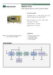
<strong>Enfora</strong> <strong>Mobile</strong> <strong>Tracker</strong>7 Geo-Fencing ConfigurationThe <strong>Enfora</strong>® <strong>Mobile</strong> <strong>Tracker</strong> allows a user to configure maximum of 25 circularshape geo-fences. <strong>Enfora</strong>® <strong>Mobile</strong> <strong>Tracker</strong>s can be configured to send GPSmessages to a remote user (server) whenever a device enters or exits a geo-fencedarea. The geo-fence feature has to be configured with two commands:AT$GEOFNC and AT$EVENT. To configure sending messages when a deviceenters or exits the geo fenced area, follow the example below:• NMEA messages provide Latitude and Longitude information in “DegreesMinute.Minute” format.• To obtain the decimal value for Degrees, take Minute.Minute of the actualLatitude or Longitude and divide it by 60.• Latitude value should be between –90.0 to +90.0 Degrees• Longitude value should be between –180.0 to +180.0 Degrees.• Latitude North of Equator line should always be positive Value.• Latitude South of the Equator line should always be negative value.• Longitude East of the GMT line should always be positive.• Longitude West of the GMT line should always be negativeNorthGMTWestEquatorEastSouthFigure 1 Map of World Displaying Latitude and LongitudeEx: Send a NMEA RMC GPS message when the <strong>Mobile</strong> <strong>Tracker</strong> moves in/out ofthe geo-fence area 1. Geo fence 1 is a 100 meter radius from the center pointdefined by Latitude = 33 01.5023 (North) and Longitude = 096 42.3853 (West).According to figure 6 above, Latitude of 33 01.5023 (North) would be a positivevalue (since its above the Equator line) but Longitude of 96 42.3853 (West) wouldbe a negative value since it is west of the GMT line.<strong>Event</strong> <strong>Cookbook</strong> P a g e 35 Revision: 1.02
<strong>Enfora</strong> <strong>Mobile</strong> <strong>Tracker</strong>Verify each AT command sent to the modem returns OK.Radius:100 metersLatitude: 33 01.5023 North = 33 + 01.5023/60= 33.02503833Longitude: 096 42.3853 West = -96 + 42.3853/60= -96.70642167AT$GEOFNC= 1,100,33.02503833,-96.706421677.1 SEND A GPS MESSAGE WHEN THE UNIT LEAVESGEO-FENCE 1AT$EVENT= 14, 0, 21, 0, 0,Transition OUT of geo-fence areaTransition OUT of geo-fence areaGeo-Fence 1Input transition event<strong>Event</strong> group 14AT$EVENT= 14, 3, 40, 14, 4350,OTA Message (ASCII RMC NMEA msg)User Specified numberSend OTA UDP MessageOutput event<strong>Event</strong> group 14Send a GPS message when the unit enters geo-fence 1<strong>Event</strong> <strong>Cookbook</strong> P a g e 36 Revision: 1.02
<strong>Enfora</strong> <strong>Mobile</strong> <strong>Tracker</strong>AT$EVENT= 15, 0, 21, 1, 1,Transition IN the geo-fence areaTransition IN the geo-fence areaGeo-Fence 1Input transition event<strong>Event</strong> group 15AT$EVENT= 15, 3, 40, 15, 4350,OTA Message (ASCII RMC NMEA msg)User Specified numberSend OTA UDP MessageOutput event<strong>Event</strong> group 15Results:A GPS RMC NMEA message will be sent to a remote user every time the deviceenters or exits the geo fence area.To add Geo-Fence 2, send the following commands to the MT-G and verify that anOK is returned.AT$GEOFNC=2,100,34.02503833,-97.70642167AT$EVENT=16,0,22,0,0AT$EVENT=16,3,40,16,4350AT$EVENT=17,0,22,1,1AT$EVENT=17,3,40,17,4350<strong>Event</strong> <strong>Cookbook</strong> P a g e 37 Revision: 1.02
<strong>Enfora</strong> <strong>Mobile</strong> <strong>Tracker</strong>For additional Geofences, repeat the 5 commands below by changing theGeoFence (index) number (A), radius (100), latitude (34.02503833), and longitude (-97.70642167) information for AT$GEOFNC command.And, increment the <strong>Event</strong> group numbers (B, C), Input <strong>Event</strong> (D), and UserSpecified Number (E, F) for AT$EVENT command.Use the following table for the relationship between the numbersAT$GEOFNC=A,100,34.02503833,-97.70642167AT$EVENT=B,0,D,0,0AT$EVENT=B,3,40,E,4350AT$EVENT=C,0,D,1,1AT$EVENT=C,3,40,F,4350GeoFenceInput Trigger<strong>Event</strong> numberLeave GeoFenceEnter GeoFence<strong>Event</strong> User Number <strong>Event</strong> User NumberA D B E C F1 21 14 14 15 152 22 16 16 17 173 23 18 18 19 194 24 20 20 21 215 25 22 22 23 236 31 24 24 25 257 32 26 26 27 278 33 28 28 29 299 34 30 30 31 3110 35 32 32 33 3311 36 34 34 35 3512 37 36 36 37 3713 38 38 38 39 3914 39 40 40 41 4115 40 42 42 43 43<strong>Event</strong> <strong>Cookbook</strong> P a g e 38 Revision: 1.02
<strong>Enfora</strong> <strong>Mobile</strong> <strong>Tracker</strong>16 41 44 44 45 4517 42 46 46 47 4718 43 48 48 49 4919 44 50 50 51 5120 45 52 52 53 5321 46 54 54 55 5522 47 56 56 57 5723 48 58 58 59 5924 49 60 60 61 6125 50 62 62 63 63Results:A GPS RMC NMEA message will be sent to the IP address (set by AT$FRIEND)and port number (set by AT$UDPAPI) when it enters or exits a defined geo fence.The output message format is generated based on the number “4350” set in aboveexample with the AT$EVENT command.<strong>Event</strong> <strong>Cookbook</strong> P a g e 39 Revision: 1.02
<strong>Enfora</strong> <strong>Mobile</strong> <strong>Tracker</strong>Warning: Bytes 32 – 42 will change depending on what isprogrammed in the “user specified field”. Bytes 81 – 83 willchange with geo-fence numberDescribed below is the data package that should be received by the Server whenthe modem exits GeoFence 1.• Row 1 indicates the Byte number.Note: Bytes 0 through 27 are part of IPV4 header. Bytes 28 andgreater are the actual packet Payload. Bytes 32 and greater arecontrolled by the Parameter 2 value.• Row 2 displays the data in HEX format, and• Row 3 and/or 4 describe each block of the message.<strong>Event</strong> <strong>Cookbook</strong> P a g e 40 Revision: 1.02
<strong>Enfora</strong> <strong>Mobile</strong> <strong>Tracker</strong>ByteByteByteByteByteByteByteByteByteByteByteByteByteByteByteByte0123456789101112131415IP Header dataIP HeaderByte16Byte17Byte18Byte19Byte20Byte21Byte22Byte23Byte24Byte25Byte26Byte27Byte28Byte29Byte30ByteUDP Header data 00 04 02 00IP Header (contd…) UDP Header ASCII GPSdataStatusUDP-API Header31reservedByte32Byte33Byte34Byte35Byte36Byte37Byte38Byte39Byte40Byte41Byte42Byte43Byte44Byte45Byte46Byte4720 20 20 20 20 20 20 20 31 34 20 20 20 20 20 20User Specified Number (14)Modem IDByte48Byte49Byte50Byte51Byte52Byte53Byte54Byte55Byte56Byte57Byte58Byte59Byte60Byte61Byte62Byte6320 20 20 20 20 20 20 20 20 4d 54 5f 54 65 73 74Modem ID continued… (MT_Test)Byte64Byte65Byte66Byte67Byte68Byte69Byte70Byte7120 66 39 2C 20 36 20 31 37 34 38 20 31 37 34 38ModemIDcont.MaskcommaGPIODataspaceByte72Byte73Byte74Byte75Byte76Byte77A/D 1 A/D 2Byte78Byte79Byte80Byte81Byte82Byte83Byte84Byte85Byte86Byte8720 32 31 20 24 47 50 52 4d 43 2c 31 39 32 35 32Byte88A/D 2 continued Input <strong>Event</strong> Number (21) ASCII NMEA RMC messageByte89Byte90Byte91Byte92Byte93Byte94Byte95($GPRMC,192527.88,A,3301.4850,N,09642.5504,W,21.1,269.8,210704,05,E*59)<strong>Event</strong> <strong>Cookbook</strong> P a g e 41 Revision: 1.02
<strong>Enfora</strong> <strong>Mobile</strong> <strong>Tracker</strong>Byte96Byte97Byte98Byte99Byte100Byte101Byte102Byte10337 2e 38 38 2c 41 2c 33 33 30 31 2e 34 38 35 30Byte104Byte105Byte106ASCII NMEA RMC message continued…Byte107Byte108Byte109Byte110Byte111Byte112Byte113Byte114Byte115Byte116Byte117Byte118Byte1192c 4e 2c 30 39 36 34 32 2e 35 35 30 34 2c 57 2cByte120Byte121Byte122ASCII NMEA RMC message continued…Byte123Byte124Byte125Byte126Byte127Byte128Byte129Byte130Byte131Byte132Byte133Byte134Byte13532 31 2e 31 2c 32 36 39 2e 38 2c 32 31 30 37 30Byte136Byte137Byte138ASCII NMEA RMC message continued…Byte139Byte140Byte141Byte142Byte143Byte144Byte145Byte146Byte147Byte148Byte149Byte150Byte151Byte152Byte153Byte15434 2c 30 35 2c 45 2a 35 39 0d 0aASCII NMEA RMC message continued…<strong>Event</strong> <strong>Cookbook</strong> P a g e 42 Revision: 1.02
<strong>Enfora</strong> <strong>Mobile</strong> <strong>Tracker</strong>8 Power Save Configuration<strong>Enfora</strong>® <strong>Mobile</strong> <strong>Tracker</strong>s allow a user to configure the device to enter or exit lowpower mode based on Ignition and/or DTR setting. The <strong>Enfora</strong>® <strong>Mobile</strong> <strong>Tracker</strong>has to be configured via AT commands as well as the hardware has to be wiredaccordingly to enter low power mode.8.1 ENTERING POWER SAVE MODESelect one of the options from 1 thru 6 below for your desired method to enter lowpower mode.Note: The MT-Gμ does not have a DTR input. Examples 4,5,6 do notapply to the MT-Gμ. If you are using these examples for MT-Gu,there are only three parameters available (i.e.AT$PWRSAV=,,). Please reviewGSM2338AT001 for correct syntax.MT-GL/MT-μL require 4 parameters: (i.e.AT$PWRSAV=,,,)Note: Example 3 only needs to be used if the MT-G does notautomatically reset when Ignition source is applied.Note: Do not use a delay time of 0 if you are planning to include GPSmessages.1. Enter the following command to put the MT in Low Power Mode immediatelywhen Ignition is turned OFF. The MT should respond back with OK.AT$PWRSAV=0,1,1,0<strong>Event</strong> <strong>Cookbook</strong> P a g e 43 Revision: 1.02
<strong>Enfora</strong> <strong>Mobile</strong> <strong>Tracker</strong>2. Enter the following command to put the MT in Low Power Mode 10 secondsafter the Ignition has been turned OFF. The MT should respond back with OK.AT$PWRSAV=0,1,10,03. Enter the following command to reset the MT when Ignition is turned ON afterbeing in low power mode during Ignition Off. The MT should respond back withOK.AT$PWRSAV=0,1,10,14. Enter the following command to put the MT-G in Low Power Mode immediatelywhen DTR is disconnected. The MT-G should respond back with OK.AT$PWRSAV=1,0,1,05. Enter the following command to put the MT-G in Low Power Mode immediatelywhen DTR is disconnected. When DTR is connected, the MT-G will reset. TheMT-G should respond back with OK.AT$PWRSAV=1,0,1,16. Enter the following command to put the MT-G in Low Power Mode 10 secondsafter DTR is disconnected and Ignition is turned OFF. The MT-G should respondback with OK.AT$PWRSAV=1,1,10,0Note: In Low Power Mode, the GPS receiver is turned OFF andhence one would not get any GPS data through the serial port orOTA. However, the modem is still registered and connected to theGSM/GPRS network. A user can also select to get notified when the<strong>Enfora</strong>® <strong>Mobile</strong> <strong>Tracker</strong> enters low power mode or exits Low PowerMode. Use the following AT commands to configure sending ofmessage when the MT enters or exits low power mode.<strong>Event</strong> <strong>Cookbook</strong> P a g e 44 Revision: 1.02
<strong>Enfora</strong> <strong>Mobile</strong> <strong>Tracker</strong>8.2 SEND A GPS MESSAGE WHEN THE ENFORA®MOBILE TRACKER EXITS POWER SAVE MODEAT$EVENT= 64, 0, 26, 0, 0,Exit power save modeExit power save modeLow Power Mode <strong>Event</strong>Input transition event<strong>Event</strong> group 64AT$EVENT= 64, 3, 40, 64, 4350,OTA Message (ASCII RMC NMEA msg)User Specified numberSend OTA UDP MessageOutput event<strong>Event</strong> group 64<strong>Event</strong> <strong>Cookbook</strong> P a g e 45 Revision: 1.02
<strong>Enfora</strong> <strong>Mobile</strong> <strong>Tracker</strong>8.3 SEND A GPS MESSAGE WHEN THE MT-G ENTERSPOWER SAVE MODEAT$EVENT= 65, 0, 26, 1, 1,Enter power save modeEnter power save modeLow Power Mode <strong>Event</strong>Input transition event<strong>Event</strong> group 65AT$EVENT= 65, 3, 40, 65, 4350,OTA Message (ASCII RMC NMEA msg)User Specified numberSend OTA UDP MessageOutput event<strong>Event</strong> group 65Results:A GPS RMC NMEA message will be sent to a remote user every time the deviceenters or exits low power mode.<strong>Event</strong> <strong>Cookbook</strong> P a g e 46 Revision: 1.02
<strong>Enfora</strong> <strong>Mobile</strong> <strong>Tracker</strong>9 GPS Idle TriggerThe <strong>Enfora</strong>® <strong>Mobile</strong> <strong>Tracker</strong> maintains GPS Idle count. The Idle count isincremented every second that the unit has not moved and is stationary in oneposition. The user can elect to receive a GPS message when the Idle countexceeds. Idle count is measured in seconds.Note: A GPS Idle Trigger message will only be sent once when thetimer expires. The message will not be repeated if the device/vehiclehas not moved.To send a GPS message when the device/vehicle stays idle for 2 minutes (120seconds), configure as follows:AT$EVENT= 68, 0, 30, 120, 1000000,Max timeout valueIdle time in seconds (120 seconds)GPS Idle Trigger Input <strong>Event</strong>Input transition event<strong>Event</strong> group 68AT$EVENT= 68, 3, 40, 68, 4350,OTA Message (ASCII RMC NMEA msg)User Specified numberSend OTA UDP MessageOutput event<strong>Event</strong> group 68<strong>Event</strong> <strong>Cookbook</strong> P a g e 47 Revision: 1.02
<strong>Enfora</strong> <strong>Mobile</strong> <strong>Tracker</strong>Query the EVENT table:AT$EVENT?The table should reflect the following:$EVENT: evgp evtyp evcat p1 p268A 0 30 120 100000068 3 40 68 4350<strong>Event</strong> <strong>Cookbook</strong> P a g e 48 Revision: 1.02
<strong>Enfora</strong> <strong>Mobile</strong> <strong>Tracker</strong>10 GPS Invisible TriggerThe <strong>Enfora</strong>® <strong>Mobile</strong> <strong>Tracker</strong> maintains GPS Invisible count. The Invisible count isincremented every second when the unit does not have valid GPS data. The usercan elect to receive a message when the Invisible count exceeds a set period.Invisible count is measured in seconds.Note: A GPS Invisible Trigger message will only be sent once whenthe timer expires. The message will not be repeated if thedevice/vehicle has not acquired valid GPS data.To send a message when the device/vehicle stays idle for 1 minute (60 seconds),configure as follows:AT$EVENT= 69, 0, 29, 60, 1000000,Max timeout valueIdle time in seconds (60 seconds)GPS Invisible Trigger Input <strong>Event</strong>Input transition event<strong>Event</strong> group 69AT$EVENT= 69, 3, 40, 69, 4350,OTA Message (ASCII RMC NMEA msg)User Specified numberSend OTA UDP MessageOutput event<strong>Event</strong> group 69<strong>Event</strong> <strong>Cookbook</strong> P a g e 49 Revision: 1.02
<strong>Enfora</strong> <strong>Mobile</strong> <strong>Tracker</strong>Query the EVENT table:AT$EVENT?The table should reflect the following:$EVENT: evgp evtyp evcat p1 p269A 0 29 60 1000000698 3 40 69 4350<strong>Event</strong> <strong>Cookbook</strong> P a g e 50 Revision: 1.02
<strong>Enfora</strong> <strong>Mobile</strong> <strong>Tracker</strong>AT$EVENT= 73, 3, 41, 911, 4102,OTA Message (ASCII RMC NMEAmsg)User Specified numberSend OTA UDP MessageOutput event<strong>Event</strong> group 72Press the “Panic” button on the <strong>Enfora</strong>® <strong>Mobile</strong> <strong>Tracker</strong>. The LED attached toGPIO 3 will begin to flash at ¼ second intervals. Also the <strong>Enfora</strong>® <strong>Mobile</strong> <strong>Tracker</strong>will start sending UDP messages as programmed in step 2.<strong>Event</strong> <strong>Cookbook</strong> P a g e 52 Revision: 1.02
<strong>Enfora</strong> <strong>Mobile</strong> <strong>Tracker</strong>After a couple of messages, enable the “Auto ACK” button. One more messageshould be sent and then the messages will stop.To extinguish to LED type in the AT Command AT$IOGP3=0 in the“Command/Data box. Click on the “Write” button to send the AT command to the<strong>Mobile</strong> <strong>Tracker</strong>. The LED attached to GPIO 3 will stop flashing.<strong>Event</strong> <strong>Cookbook</strong> P a g e 53 Revision: 1.02
<strong>Enfora</strong> <strong>Mobile</strong> <strong>Tracker</strong><strong>Event</strong> <strong>Cookbook</strong> P a g e 54 Revision: 1.02
<strong>Enfora</strong> <strong>Mobile</strong> <strong>Tracker</strong>12 Door Switch Detect To SMS MessageIn this example the <strong>Enfora</strong>® <strong>Mobile</strong> <strong>Tracker</strong> will be configured to monitor a pushbutton switch, such as the “door ajar” switch mounted on a vehicle, to inform theuser via SMS messages on the state of the switch.1. Add the following AT$EVENT commands to the <strong>Enfora</strong>® <strong>Mobile</strong> <strong>Tracker</strong> “StockFactory Configuration.”AT$EVENT= 73, 0, 0, 1, 1,Ending range of 1 (high)Starting range of 1 (high)Activity on I/O line #1 based on rangeInput transition event<strong>Event</strong> group 73AT$EVENT= 73, 3, 44, 1, 0,N/AExecute First AT$STOATEV CommandExecute AT$STOATEVOutput transition event<strong>Event</strong> group 73AT$EVENT= 74, 0, 0, 0, 0,Ending range of 0 (low)Starting range of 0 (low)Activity on I/O line #1 based onrangeInput transition event<strong>Event</strong> group 74<strong>Event</strong> <strong>Cookbook</strong> P a g e 55 Revision: 1.02
<strong>Enfora</strong> <strong>Mobile</strong> <strong>Tracker</strong>AT$EVENT= 74, 3, 44, 2, 0,N/AExecute Second AT$STOATEVCommandExecute AT$STOATEVOutput transition event<strong>Event</strong> group 742. Set the <strong>Enfora</strong>® <strong>Mobile</strong> <strong>Tracker</strong>’s AT$STOATEV to send the “Door State” SMSmessages.AT$STOATEV=1, AT+CMSS=1AT$STOATEV=2, AT+CMSS=23. Create the following SMS messages and save to the SIM card. Note: delete allSMS messages from the SIM card or take note of what message number isassigned to the stored SMS message. Then adjust AT$STOATEV accordingly.You can use a telephone number that can receive SMS messages such as aGSM cell phone or you can substitute the carrier’s email gateway for thetelephone number. See application note: GSM0000AN016 “How to Send anSMS Message to an E-Mail Address” for more information.AT+CMGW=”5555551212”> Door Closed Note:This is message #1 as stored in the SIM Card.AT+CMGW=”5555551212”> Door Open <strong>Event</strong> <strong>Cookbook</strong> P a g e 56 Revision: 1.02
<strong>Enfora</strong> <strong>Mobile</strong> <strong>Tracker</strong>Note: This is message #2 as stored in the SIM Card.4. Save the settings by using:AT&W5. Reset the Modem and allow it to attach to the GSM/GPRS Network.6. When the switch is pushed on the modem, it will send the SMS message storedin AT$STOATEV=2. When the switch is released the SMS message stored inAT$STOATEV=1.<strong>Event</strong> <strong>Cookbook</strong> P a g e 57 Revision: 1.02
<strong>Enfora</strong> <strong>Mobile</strong> <strong>Tracker</strong>13 <strong>Event</strong>s to Detect Primary Power LossIn this example the <strong>Enfora</strong>® MT-μL (GSM2238-00) will be configured to monitorand display to the terminal program, what power source it is currently running from.1. Add the following AT$EVENT commands to the <strong>Enfora</strong>® <strong>Mobile</strong> <strong>Tracker</strong> “StockFactory Configuration.”AT$EVENT= 90, 0, 3, 1, 1,Ending range of 1 (high)Starting range of 1 (high)Activity on I/O line #4 based on rangeInput transition event<strong>Event</strong> group 90AT$EVENT= 90, 3, 44, 1, 0,N/AExecute First AT$STOATEV CommandExecute AT$STOATEVOutput transition event<strong>Event</strong> group 90AT$EVENT= 91, 0, 3, 0, 0,Ending range of 0 (low)Starting range of 0 (low)Activity on I/O line #4 based onrangeInput transition event<strong>Event</strong> group 91<strong>Event</strong> <strong>Cookbook</strong> P a g e 58 Revision: 1.02
<strong>Enfora</strong> <strong>Mobile</strong> <strong>Tracker</strong>AT$EVENT= 91, 3, 44, 2, 0,N/AExecute Second AT$STOATEVCommandExecute AT$STOATEVOutput transition event<strong>Event</strong> group 912. Set the <strong>Enfora</strong>® <strong>Mobile</strong> <strong>Tracker</strong>’s AT$STOATEV to send the “Power State” viaASCII messages to the terminal program.AT$STOATEV=1, AT$MSGSND=0,”Running on external power”AT$STOATEV=2, AT$MSGSND=0,”Running on internal battery”3. Save the settings by using:AT&W4. Turn the primary power supply OFF, the following message will be displayedfrom the <strong>Mobile</strong> <strong>Tracker</strong>.<strong>Event</strong> <strong>Cookbook</strong> P a g e 59 Revision: 1.02
<strong>Enfora</strong> <strong>Mobile</strong> <strong>Tracker</strong>5. Turn the primary power supply ON; the following message will be displayedfrom the <strong>Mobile</strong> <strong>Tracker</strong>.<strong>Event</strong> <strong>Cookbook</strong> P a g e 60 Revision: 1.02
<strong>Enfora</strong> <strong>Mobile</strong> <strong>Tracker</strong>14 <strong>Event</strong>s Biased on GPIO 1 ($IOPULUP)In this example the <strong>Enfora</strong>® MT-μL (GSM2238-00 or -01) will be configured tomonitor and display to the terminal program, the logic state of GPIO 1.1. Add the following AT$EVENT commands to the <strong>Enfora</strong>® <strong>Mobile</strong> <strong>Tracker</strong> “StockFactory Configuration.”AT$EVENT= 82, 0, 0, 1, 1,Ending range of 1 (high)Starting range of 1 (high)Activity on I/O line #4 based on rangeInput transition event<strong>Event</strong> group 92AT$EVENT= 92, 3, 44, 1, 0,N/AExecute First AT$STOATEV CommandExecute AT$STOATEVOutput transition event<strong>Event</strong> group 92AT$EVENT= 93, 0, 0, 0, 0,Ending range of 0 (low)Starting range of 0 (low)Activity on I/O line #4 based on rangeInput transition event<strong>Event</strong> group 93<strong>Event</strong> <strong>Cookbook</strong> P a g e 61 Revision: 1.02
<strong>Enfora</strong> <strong>Mobile</strong> <strong>Tracker</strong>AT$EVENT= 68, 3, 40, 68, 4350,N/AExecute Second AT$STOATEVCommandExecute AT$STOATEVOutput transition event<strong>Event</strong> group 932. Set the <strong>Enfora</strong>® <strong>Mobile</strong> <strong>Tracker</strong>’s AT$STOATEV to send the “Power State” viaASCII messages to the terminal program.AT$STOATEV=1, AT$MSGSND=0,”GPIO 1 is in the HIGH State”AT$STOATEV=2, AT$MSGSND=0,”GPIO 1 is in the LOW State”3. Set the GPIO 1 pull-up to LOW by issuing:AT$IOPULUP=04. Save the settings by using:AT&W5. Connect GPIO 1 to a positive power source; the modem will display thefollowing in the terminal program.<strong>Event</strong> <strong>Cookbook</strong> P a g e 62 Revision: 1.02
<strong>Enfora</strong> <strong>Mobile</strong> <strong>Tracker</strong>6. Disconnect GPIO 1; the modem will display the following in the terminalprogram.<strong>Event</strong> <strong>Cookbook</strong> P a g e 63 Revision: 1.02