Fan Coil - Daikin AC
Fan Coil - Daikin AC
Fan Coil - Daikin AC

You also want an ePaper? Increase the reach of your titles
YUMPU automatically turns print PDFs into web optimized ePapers that Google loves.
D<strong>AC</strong>A-EFWT10-2011
2. Specification - Hydronic <strong>Fan</strong> <strong>Coil</strong> EFWT2.1 EFWT_AEVLU: 120V/1PH/60HZ (ECM Motor with no Electric Heat Options)Capacity 018 024 030 036 048 060Model Number(No Electric Heat Options)**EFWT018AEVLU EFWT024AEVLU **EFWT030AEVLU EFWT036AEVLU EFWT048AEVLU EFWT060AEVLUCooling Performance:Nominal Capacity Btu/hr 19,100 22,600 28,600 32,000 42,700 52,400Nominal Sensible Capacity Btu/hr 14,200 17,700 22,400 25,800 34,700 42,400EWT Range °F 42 - 50°FNominal Flow Rate GPM 4.5 5.0 6.0 6.0 8.0 10Nominal Pressure drop Ft Hd 5.5 7.7 4.8 5.5 5.4 7.9Heating Performance:Nominal Capacity Btu/hr 19,300 25,000 31,900 34,800 50,200 60,900EWT Range °F 100 - 125°FNominal Flow Rate GPM 3.0 4.5 6.0 6.0 8.0 10Nominal Pressure drop Ft Hd 2.5 5.5 4.8 5.5 5.4 7.9Airflow Rate:Nominal CFM 600 800 1050 1200 1600 1825Total External Static Pressure WG 0.3" WG Std 0.5" WG MaxBlower Speed setting"C" FIELDSETTING"A" F<strong>AC</strong>TORYSETTING"B" FIELDSETTING"A" F<strong>AC</strong>TORYSETTING"A" F<strong>AC</strong>TORYSETTING"A" F<strong>AC</strong>TORYSETTINGMotor rating HP 1/3 HP 1/2 HP 3/4 HP 1 HPAirflow arrangementUpflow, Horizontal L, Horizontal R (Possible)Electrical Data:Power supply120V / 1 / 60HzMinimum Circuit Amps6.0 6.0 10 10 14 15(MCA)AMax. overcurent protection15 15 15 15 15 15(MOP)Physical Data:Dimension (H x W x D) in. 40 x 20 x 20 40 x 23 x 20 48 x 21-1/4 x 28Weight lbs. 115 170 230 290insulation type / R-Rating1/2" JM TUF-SKINInstallation ClearancesU.L. Listed For Installation With Zero Inches Clearance To Combustible MaterialsConnection type:Inlet / Outlet Connections in. 3/4 3/4 3/4 3/4 1 1Connection TypeSweatFeature:Thermostat Connection24VAir Filter (MERV 8 Throwaway) in. 18 x 20 x 1 20 x 22 x 1 20 x 25 x 1Notes:1. Cooling Capacity is based on 50°F Entering Water Temp and 80°F DB/67°F WB Entering Air Conditions.2. Heating Capacity is based on 110°F Entering Water Temp and 70°F DB Entering Air Conditions.3. Refer to detailed capacity tables for further information pertaining to the entire entering water temperature range and for flow rates and pressure drop.4. ** - Models downsized by adjusting air flow rate during installationCopyright 2011 <strong>Daikin</strong> <strong>AC</strong>. Printed in U.S.A. Edition Date: 10/2011<strong>Daikin</strong> <strong>AC</strong> reserves the right to change, at any time, specifications and designs without notice and without obligations.4 | P age
3. Capacity Tables3.1 Heating Performance DataUNITMODELCapacity(MBH)NOMCFM**EFWT018 18.0 600EFWT024 24.0 800**EFWT030 30.0 1050EFWT036 36.0 1200EFWT048 48.0 1600EFWT060 60.0 1825GPM P.D.Heating BTUH @ Entering Water Temp.(HTG) (Ft Wt.) 100°F 105°F 110°F 115°F 120°F 125°F4 4.4 15.1 17.6 20.1 22.6 25.1 27.63 2.5 14.4 16.8 19.3 21.7 24.1 26.52 1.2 13.5 15.7 17.9 20.2 22.4 24.76 9.5 19.5 22.8 26.0 29.3 32.6 35.84.5 5.5 18.8 21.9 25.0 28.2 31.3 34.43 2.5 17.5 20.5 23.4 26.3 29.2 32.26 4.8 25.1 29.2 33.4 37.0 41.8 45.94.5 3.0 23.9 27.9 31.9 35.9 39.8 43.83 1.5 22.1 25.8 29.5 33.1 36.8 40.56 4.8 27.5 32.0 36.6 41.2 45.8 50.34.5 3.0 26.1 30.5 34.8 39.2 43.5 47.93 1.5 24.0 28.0 32.0 36.0 39.9 43.910 7.9 39.0 45.5 52.0 58.5 65.0 71.58 5.4 37.7 44.4 50.2 56.5 62.8 69.16 3.3 35.8 41.8 47.8 49.2 59.7 65.713 12.5 44.2 51.6 59.0 66.4 73.7 81.110 7.9 42.7 49.8 57.0 64.1 71.2 78.37 4.3 40.2 46.9 53.6 60.3 67.0 73.73.2 Cooling Performance DataUNITMODELCapacity(MBH)NOM.CFM**EFWT018 18.0 600EFWT024 24.0 800**EFWT030 30.0 1000EFWT036 36.0 1200EFWT048 48.0 1600EFWT060 60.0 1825GPMP.D.(FT. WT.)TOTALMBH50°F ENTERING WATER80°F DB/67°F WB ENT. AIR 75°F DB/63°F WB ENT. AIRSENS TEMP TOTAL SENSMBHRISE MBHMBHTEMPRISE3 2.5 16.3 13.2 10.8 12.4 11.7 8.34.5 5.5 19.1 14.2 8.5 14.6 12.5 6.56 9.5 20.8 14.9 6.9 15.9 13.0 5.33.5 3.4 19.5 16.6 11.2 14.9 14.7 8.55 6.7 22.6 17.7 9.1 17.3 15.6 6.96.5 11 24.6 18.4 7.6 18.8 16.2 5.84 2.4 24.0 20.7 12.0 18.4 18.4 9.26 4.8 28.6 22.4 9.5 21.8 19.7 7.38 7.9 31.4 23.4 7.9 24.0 20.6 6.04.5 3.5 28.6 24.5 11.4 21.8 21.8 8.76 5.5 32.0 25.8 9.9 24.5 22.8 7.58 7.9 34.5 26.7 8.6 26.4 23.5 6.66 3.3 37.3 32.7 12.4 29.1 29.1 9.78 5.4 42.7 34.7 10.7 32.6 30.6 8.210 7.9 46.6 36.1 9.3 35.6 31.8 7.17 4.3 42.3 36.9 12.1 32.8 32.8 9.410 7.9 49.6 39.5 9.9 37.9 3.9 7.613 12.5 54.2 41.3 8.3 41.4 36.3 6.4Copyright 2011 <strong>Daikin</strong> <strong>AC</strong>. Printed in U.S.A. Edition Date: 10/2011<strong>Daikin</strong> <strong>AC</strong> reserves the right to change, at any time, specifications and designs without notice and without obligations.7 | P age
Cooling Performance Data (Con’t.)UNITMODELCapacity(MBH)NOM.CFM**EFWT018 18.0 600EFWT024 24.0 800**EFWT030 30.0 1000EFWT036 36.0 1200EFWT048 48.0 1600EFWT060 60.0 1825**EFWT018 18.0 600EFWT024 24.0 800**EFWT030 30.0 1000EFWT036 36.0 1200EFWT048 48.0 1600EFWT060 60.0 1825**EFWT018 18.0 600EFWT024 24.0 800**EFWT030 30.0 1000EFWT036 36.0 1200EFWT048 48.0 1600EFWT060 60.0 1825GPMP.D.(FT. WTR.)45°F ENTERING WATER80°F DB/67°F WB ENT. AIR 75°F DB/63°F WB ENT. AIRTOTAL MBH SENS MBH TEMP RISE TOTAL MBH SENS MBH TEMP RISE3 2.5 19.0 13.8 12.7 14.5 12.1 9.74.5 5.5 22.4 15.1 9.9 17.1 13.1 7.66 9.5 24.4 15.9 8.2 18.7 13.7 6.23.5 3.4 23.1 17.3 13.2 17.6 15.2 10.15 6.7 26.9 18.7 10.7 20.5 16.3 8.26.5 11 29.2 19.6 9.0 22.3 17.0 6.94 2.4 28.3 21.6 14.1 21.6 19.0 10.86 4.8 33.9 23.7 11.3 25.9 20.6 8.68 7.9 37.3 25.0 9.3 28.5 21.7 7.14.5 3.5 33.7 25.5 13.5 25.8 22.4 10.36 5.5 38.0 27.1 11.7 29.1 23.7 8.98 7.9 41.0 28.2 10.3 31.3 24.6 7.86 3.3 44.2 34.1 14.7 33.8 30.0 11.38 5.4 51.0 36.6 12.7 38.9 32.0 9.710 7.9 55.7 38.4 11.1 42.5 33.4 8.57 4.3 49.7 39.6 14.2 38.0 35.0 10.810 7.9 58.3 42.8 11.7 44.5 37.5 8.913 12.5 63.8 44.9 9.8 48.7 39.1 7.542°F ENTERING WATER3 2.5 20.7 14.4 13.8 15.8 12.6 10.54.5 5.5 24.4 15.9 10.8 18.6 13.7 8.36 9.5 26.6 16.8 8.9 20.3 14.4 6.83.5 3.4 25.2 18.1 14.4 19.2 15.8 11.05 6.7 29.3 19.6 11.7 22.4 17.1 8.96.5 11.0 31.8 20.6 9.8 24.3 17.8 7.54 2.4 30.8 22.5 15.4 23.6 19.7 11.86 4.8 36.9 24.8 12.3 28.2 21.6 9.48 7.9 40.6 26.3 10.2 31.0 22.7 7.84.5 3.5 36.8 26.6 14.7 28.1 23.3 11.36 5.5 41.5 28.4 12.8 31.7 24.7 9.78 7.9 44.7 29.6 11.2 34.1 25.7 8.56 3.3 48.2 35.5 16.1 36.8 31.2 12.38 5.4 55.5 38.3 13.9 42.4 33.4 10.610 7.9 60.7 40.3 12.1 46.3 34.9 9.37 4.3 54.2 41.2 15.5 41.4 36.3 11.810 7.9 63.6 44.8 12.7 48.6 39.1 9.313 12.5 69.5 47.1 10.7 53.1 40.9 7.840° F ENTERING WATER3 2.5 22.0 15.4 14.7 16.8 13.4 11.24.5 5.5 25.8 16.8 11.5 19.7 14.5 8.76 9.5 28.1 17.8 9.4 21.5 15.3 7.23.5 3.4 26.4 19.1 15.1 20.2 16.7 11.55 6.7 30.6 20.7 12.2 23.4 18.0 9.46.5 11.0 33.3 21.8 10.2 25.4 18.8 7.84 2.4 32.5 23.8 16.2 24.8 20.9 12.46 4.8 38.7 26.2 12.9 29.5 22.7 9.88 7.9 42.5 27.7 10.6 32.5 23.9 8.14.5 3.5 36.7 27.5 16.3 28.0 24.1 12.56 5.5 43.4 30.0 13.3 32.1 25.7 10.78 7.9 46.7 31.3 11.7 35.7 27.1 8.96 3.3 50.5 37.5 16.8 38.6 32.9 12.98 5.4 57.8 40.3 14.5 44.2 35.1 11.010 7.9 63.1 42.4 12.6 48.2 36.7 9.67 4.3 57.2 42.4 16.3 43.7 37.1 12.510 7.9 67.1 46.1 13.4 51.2 40.1 10.213 12.5 73.4 48.6 11.3 56.0 42.0 8.6Copyright 2011 <strong>Daikin</strong> <strong>AC</strong>. Printed in U.S.A. Edition Date: 10/2011<strong>Daikin</strong> <strong>AC</strong> reserves the right to change, at any time, specifications and designs without notice and without obligations.8 | P age
4. Electrical DataA separate power supply will be required of 120, 208/230 volts, 1 ph, 60 Hz. 2-pipe units are available in 120V/60or 208-230V/60. 2-pipe with electric heat, are available in 208-230/60 only.Optional Accessories Available:Units are available with electric heat from 5-25kW. Electric heat is a factory installed options.4.1 EFWT_AEVLU: 120V/1PH/60HZ (ECM Motor with no Electric Heat Options)Model NumberMin. Circuit Amps Max. Overcurrent ProtectionFull Load Amps<strong>Fan</strong> HP(MCA)(MOP)(FLA)**EFWT018AEVLU 6 15 1/3 4.8EFWT024AEVLU 6 15 1/3 4.8**EFWT030AEVLU 10 15 1/2 7.3EFWT036AEVLU 10 15 1/2 7.3EFWT048AEVLU 14 15 3/4 10.5EFWT060AEVLU 15 15 1 11.54.2 EFWT_AEVJU: 208/230V/1PH/60HZ (ECM Motor with Electric Heat Options)Model NumberMin. Circuit Amps Max. Overcurrent Protection <strong>Fan</strong> HP Full Load Amps(MCA)(MOP)(FLA)**EFWT018AEVJU 3 15 1/3 1.9EFWT024AEVJU 3 15 1/3 1.9**EFWT030AEVJU 4 15 1/2 2.8EFWT036AEVJU 4 15 1/2 2.8EFWT048AEVJU 6 15 3/4 4.7EFWT060AEVJU 9 15 1 7.14.3 EFWT_APVLU: 120V/1PH/60HZ (PSC Motor with No Electric Heat options)Model NumberMin. Circuit Amps Max. Overcurrent ProtectionFull Load Amps<strong>Fan</strong> HP(MCA)(MOP)(FLA)**EFWT018APVLU 3.8 15 1/5 3.0EFWT024APVLU 3.8 15 1/5 3.0**EFWT030APVLU 7.5 15 1/3 6.0EFWT036APVLU 7.5 15 1/3 6.0EFWT048APVLU 10.0 15 1/2 8.0EFWT060APVLU 13.1 15 3/4 10.54.4 Standard Wiring EquipmentModel Number**EFWT018EFWT024**EFWT030EFWT036EFWT048EFWT060Power Supply Wiring(Including Ground Wire)Transmission Wiring RemoteControl WiringField Fuses Size Size15A Must Comply with local codes AWG18-16** Models downsized by adjusting air flow rate during installationCopyright 2011 <strong>Daikin</strong> <strong>AC</strong>. Printed in U.S.A. Edition Date: 10/2011<strong>Daikin</strong> <strong>AC</strong> reserves the right to change, at any time, specifications and designs without notice and without obligations.9 | P age
4.5 Electric Heat Options (Factory Installed)Model Number**EFWT018EFWT024**EFWT030EFWT036EFWT048EFWT060Factory Installed ElectricHeat Options (kW)05100101501520250152025Circuit 1 (240/208V) Circuit 2 (240/208V) Circuit 3 (240/208V)MCA MOP MCA MOP MCA MOP3/329/2542/364/456/4956/496/658/5058/5058/509/959/5359/5359/5315/1530/2560/5015/1560/5060/5015/1560/5060/5060/5015/1560/5060/5060/50---------------27/23---27/2353/4653/46---27/2353/4653/46---------------30/25---30/2560/5060/50---30/2560/5060/50---------------------------27/23---------27/23---------------------------30/25---------30/25Notes:1. 15kW and 20kW models require 2 supply circuits. 25kW models require 3 supply circuits.2. Units suitable for installation with 0” clearance to combustible material.5. Air Flow Data5.1 Blower Speed Selection EFWT_AEVLU, 120V (ECM Motor)Model**EFWT018EFWT024**EFWT030EFWT036EFWT048EFWT060Control Board Select TapOperating ModeCool TapHeat Tap<strong>Fan</strong> Speed Tap SettingA B C D A B C DCooling or Heating800 700 600 500 Set Cooling & HeatingThermostat SignalTo tap “C”Continuous Blower 400 350 300 250Cooling or Heating800 700 600 500 Set Cooling & HeatingThermostat SignalTo tap “A”Continuous Blower 400 350 300 250Cooling or Heating1200 1050 900 750 Set Cooling & HeatingThermostat SignalTo tap “B”Continuous Blower 600 525 400 375Cooling or Heating1200 1050 900 750 Set Cooling & HeatingThermostat SignalTo tap “A”Continuous Blower 600 525 400 375Cooling or Heating1600 1400 1200 1000 Set Cooling & HeatingThermostat SignalTo tap “A”Continuous Blower 800 700 600 500Cooling or Heating1825 1700 1600 1400 Set Cooling & HeatingThermostat SignalTo tap “A”Continuous Blower 900 850 800 700** Models downsized by adjusting air flow rate during installationCopyright 2011 <strong>Daikin</strong> <strong>AC</strong>. Printed in U.S.A. Edition Date: 10/2011<strong>Daikin</strong> <strong>AC</strong> reserves the right to change, at any time, specifications and designs without notice and without obligations.10 | P age
5.2 Blower Speed Selection EFWT_AEVJU, 208-240V (ECM Motor)Model**EFWT018EFWT024**EFWT030EFWT036EFWT048EFWT060Control Board Select TapOperating ModeCool TapHeat Tap<strong>Fan</strong> Speed Tap SettingA B C D A B C DCooling Therm. Signal 800 700 600 500 Set Cooling to tap “C”Continuous Blower 400 350 300 250Set Heating to tap “D”Unit with 0-10kW maxHeating Therm. Signal 790 730 660 600 Electric HeatCooling Therm. Signal 800 700 600 500 Set Cooling to tap “A”Continuous Blower 400 350 300 250Set Heating to tap “A”Unit with 0-10kW maxHeating Therm. Signal 790 730 660 600 Electric HeatCooling Therm. Signal 1200 1050 900 750 Set Cooling to tap “B”Continuous Blower 600 525 400 375Set Heating to tap “B”Unit with 0-15kW maxHeating Therm. Signal 1130 1000 875 790 Electric HeatCooling Therm. Signal 1200 1050 900 750 Set Cooling to tap “A”Continuous Blower 600 525 400 375Set Heating to tap “A”Unit with 0-15kW maxHeating Therm. Signal 1130 1000 875 790 Electric HeatCooling Therm. Signal 1600 1400 1200 1000 Set Cooling to tap “A”Continuous Blower 800 700 600 500Set Heating to tap “A”Unit with 0-20kW maxHeating Therm. Signal 1500 1360 1190 1060 Electric HeatCooling Therm. Signal 1825 1700 1600 1400 Set Cooling to tap “A”Continuous Blower 900 850 800 700Set Heating to tap “A”Unit with 0-25kW maxHeating Therm. Signal 1825 1700 1500 1300 Electric Heat5.3 Blower Speed Selection EFWT_APVLU, 120V (PSC Motor)ModelMotorHP-AMP**EFWT018 1/5 – 3.0EFWT024 1/5 – 3.0**EFWT030 1/3 – 6.0EFWT036 1/3 – 6.0EFWT048 1/2 – 8.0EFWT060 3/4 – 10.5MotorSpeedCFM vs. External Static Pressure0.05 0.10 0.20 0.30 0.40 0.50High 920 890 825 750 680 580Med-Hi 750 730 680 610 540 450Med-Low 555 530 480 420 330 - - -Low 350 310 240 170 100 - - -High 920 890 825 750 680 580Med-Hi 750 730 680 610 540 450Med-Low 555 530 480 420 330 - - -Low 350 310 240 170 100 - - -High 1220 1185 1120 1070 1015 960Med-Hi 1085 1060 1010 960 910 865Med-Low 935 915 875 830 775 700Low 750 730 695 650 605 500High 1220 1185 1120 1070 1015 960Med-Hi 1085 1060 1010 960 910 865Med-Low 935 915 875 830 775 700Low 750 730 695 650 605 500High 1730 1690 1620 1540 1450 1350Med 1580 1550 1490 1430 1360 1270Low 1360 1340 1310 1270 1210 1100High 2030 2000 1950 1900 1840 1770Med 1630 1615 1580 1540 1490 1440Low 1280 1270 1240 1210 1180 1140** Models downsized by adjusting air flow rate during installationCopyright 2011 <strong>Daikin</strong> <strong>AC</strong>. Printed in U.S.A. Edition Date: 10/2011<strong>Daikin</strong> <strong>AC</strong> reserves the right to change, at any time, specifications and designs without notice and without obligations.11 | P age
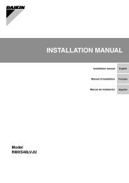
5.4 Air Flow Arrangements (Field Configurable)6. Physical Dimensions:HorizontalConvertible DrainPan Required)Drain Connections3/4” MPTCircuit Breaker(If Required)Power Entry Options(Low Voltage EntryOpposite Side)FilterConnections (All Sweat)3/4” Nominal on 018-0361” Nominal on 048-060Model Number A B C D E F G H Filter Size**EFWT018EFWT02440 20 20 18-1/2 16 2 18 16 18 x 20 x 1**EFWT030EFWT03642 23 20 21 16 2 18 17 20 x 22 x 1EFWT048 48 28 21-1/4 26-1/4 17-1/4 2 19-1/4 18 20 x 25 x 1EFWT060 48 28 21-1/4 26-1/4 17-1/4 2 19-1/4 18 20 x 25 x 1Copyright 2011 <strong>Daikin</strong> <strong>AC</strong>. Printed in U.S.A. Edition Date: 10/2011<strong>Daikin</strong> <strong>AC</strong> reserves the right to change, at any time, specifications and designs without notice and without obligations.12 | P age
7. Application:7.1 Typical Application Example for Split systemERLQOutdoor UnitSize: 018,024,030ControlValveUnder Floor HeatingWater FillValve LocationDifferentialPressureBy-Pass ValveSize: 036,048,054HeadersBuffer Tank7.2 Typical Application Example for Monobloc systemUserInterfaceEBLQ/EDLQOutdoor UnitSize: 036,048,054ControlValveUnder Floor HeatingWater FillValve LocationDifferentialPressureBy-Pass ValveHeadersBuffer TankCopyright 2011 <strong>Daikin</strong> <strong>AC</strong>. Printed in U.S.A. Edition Date: 10/2011<strong>Daikin</strong> <strong>AC</strong> reserves the right to change, at any time, specifications and designs without notice and without obligations.13 | P age
8. Installation: (Reference Installation Manual)8.1 Reference to installation manual document Numbers by model typeEFWT_AEVLU – Document No. L3778DK 8/11EFWT_AEVJU – Document No. L2478DK 8/11EFWT_APVLU – Document No. L1478DK 8/118.2 Installation notes:1. Safety Consideration – Please refer to installation manual for the “Safety Considerations for installation”.2. Before installation – be sure to read the installation manual before installing the <strong>Fan</strong> coil unit.3. Selecting installation site – Select an installation site where the following conditions are fulfilled and thatmeets with your customer’s approval.4. Installation Precautions – Always review the nameplate on each unit for proper voltage and controlconfigurations. This information is determined from the components and wiring of the unit and may vary fromunit to unit.5. Water piping work – Water piping should be tested in accordance with the relevant local, state and nationalregulation plumbing code. All water piping needs to be insulated due to high water temperature and the risk ofcondensation leaking.6. Drain piping work – Perform drain work so that the unit is drained thoroughly.7. Installing the duct – Exercise care regarding the following when performing ductwork. Verify that duct workdoes not exceed the unit’s setting range of external static pressure.8. Electric wiring work – all wiring must be performed by an authorized electrician.9. Wiring examples – Precautions when laying power supply wiring. No wiring or other work should be attemptedwithout first ensuring that the fan coil is completely disconnected from the power source and locked out. Alwaysverify that a good ground connection exists prior to energizing any power sources.10. Application and blower speed selection – Select taps are used by the installer to properly configure thesystem.11. Startup and test runa. Make sure the electric component box covers are closed on the indoor and outdoor units.Install air filterb. Check that supply voltage matches nameplate data. Ensure that the unit is properly grounded.c. With power off, check blower wheel set screw for tightness and ensure that the blower wheel rotatesfreely and quietly.d. Check that the water coil, valves and piping have been leak checked and insulated as required.e. Ensure that all air has been vented from the water coils.f. Consult <strong>Daikin</strong> Altherma Install and Operation Manuals for testing of system.g. Confirm fan coil unit operation12. Troubleshooting motor and controlsThe ECM motor contains two parts: the control module and motor winding section. Do not assume the motor ormodule is defective if it will not start. Go through the steps described below before replacing control module,Select Control Board or entire motor. The control module is available as a replacement part.If Motor turns slowly:1. Replace panel and check air filter. Motor may appear to run slowly if access panel or air filteris removed.Copyright 2011 <strong>Daikin</strong> <strong>AC</strong>. Printed in U.S.A. Edition Date: 10/2011<strong>Daikin</strong> <strong>AC</strong> reserves the right to change, at any time, specifications and designs without notice and without obligations.14 | P age
2. It is normal operation to run noticeably slower if G terminal is energized without a call for heator cooling.If Motor does not run:1. Check for 24V<strong>AC</strong> at terminal R and C1. If no voltage is present, check the transformer.Transformer is located in <strong>Daikin</strong> Altherma control box, Terminals X2M 26, 27.2. Check all plugs and receptacles for any deformation, which could cause loose connections.Be sure plugs are fully seated.3. Verify that supply voltage is present at the motor.Check control signals - Verify low voltage control signals to motor. The motor receives its control signalsthrough the 16-pin wiring harness. The combination of pins energized will determine the motor speed. Seetable 12-1 for pin number on 16-pin plug which should have voltage when Select Control Board screwterminals have 24V<strong>AC</strong>.The <strong>Fan</strong> coil units contain PSC fan motor. Do not assume the motor, relays or controls are defective if it will notstart. Go through the steps described below before replacing any parts.If Motor turns slowly:1. Check to see motor is not overloaded, dirty air filter, blocked vents, or debris in fan sectionor squirrel cage.2. Check to see ductwork is of proper size for airflow capabilities of fan coil unit.3. Check to see if motor turns freely when squirrel cage is rotated, if not pull blower assembly and see ifmotor can be lubricated. If the motor has sealed bearings replace motor.4. Check motor capacitor for bulging or leaking. If these signs are present replace just capacitor first andrecheck motor operation and amperage draw against rating plate on motor body.If Motor does not run:1. Check for 24V<strong>AC</strong> at terminal R and C1. If no voltage is present, check the transformer. Transformer islocated in <strong>Daikin</strong> Altherma control box, Terminals X2M 26, 27.2. Check motor amperage draw against rating plate on motor body. If motor still runs slow see MotorWinding Section below.3. Check all plugs and receptacles for any deformation, which could cause loose connections. Be sureplugs are fully seated.4. Verify that supply voltage is present at the motor.Check control signals - Verify low voltage control signals to motor. The motor receives its control signalsthrough the relay which is energized by R and G from the thermostat.Thermostat:1. Remove all thermostat wires from Control PCB.2. Jumper screw terminals on the select control board one at a time: R-G, R-Y1, and R-W1. If motor runsin all cases, thermostat is miss-wired, configured incorrectly, or defective. If motor runs in some cases,but not others, continue to check wiring harness and circuit board.Verify Motor Winding Section: Before proceeding with motor replacement, check the following to ensuremotor windings are functional and intact. With all motor wires disconnected:1. The resistance between any 2 motor leads should be similar; each should be within 1 or 2 ohms ofeach other.2. If one or more of any 2 motor leads have very low or ohms as compared to each other replace motor.3. The resistance between any two motor leads shows continuity or open the motor is defective.4. If motor windings fail one of these tests, it is defective and must be replaced.13. Care and maintenance – For continuing high performance, and to minimize possible equipment failure, it isessential that periodic maintenance be performed on this equipmentNOTE: In some models, not all speed taps are allowable for certain electric heat applications. Refer toInstallation Manual and Ratings plate for minimum speed.Copyright 2011 <strong>Daikin</strong> <strong>AC</strong>. Printed in U.S.A. Edition Date: 10/2011<strong>Daikin</strong> <strong>AC</strong> reserves the right to change, at any time, specifications and designs without notice and without obligations.15 | P age
9. <strong>Fan</strong> <strong>Coil</strong> Unit Wiring DiagramCopyright 2011 <strong>Daikin</strong> <strong>AC</strong>. Printed in U.S.A. Edition Date: 10/2011<strong>Daikin</strong> <strong>AC</strong> reserves the right to change, at any time, specifications and designs without notice and without obligations.16 | P age
Copyright 2011 <strong>Daikin</strong> <strong>AC</strong>. Printed in U.S.A. Edition Date: 10/2011<strong>Daikin</strong> <strong>AC</strong> reserves the right to change, at any time, specifications and designs without notice and without obligations.17 | P age
Copyright 2011 <strong>Daikin</strong> <strong>AC</strong>. Printed in U.S.A. Edition Date: 10/2011<strong>Daikin</strong> <strong>AC</strong> reserves the right to change, at any time, specifications and designs without notice and without obligations.18 | P age
Copyright 2011 <strong>Daikin</strong> <strong>AC</strong>. Printed in U.S.A. Edition Date: 10/2011<strong>Daikin</strong> <strong>AC</strong> reserves the right to change, at any time, specifications and designs without notice and without obligations.19 | P age
Copyright 2011 <strong>Daikin</strong> <strong>AC</strong>. Printed in U.S.A. Edition Date: 10/2011<strong>Daikin</strong> <strong>AC</strong> reserves the right to change, at any time, specifications and designs without notice and without obligations.20 | P age
Copyright 2011 <strong>Daikin</strong> <strong>AC</strong>. Printed in U.S.A. Edition Date: 10/2011<strong>Daikin</strong> <strong>AC</strong> reserves the right to change, at any time, specifications and designs without notice and without obligations.21 | P age
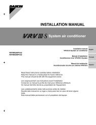
EFWT_APVLU <strong>Fan</strong> <strong>Coil</strong> (120V-PSC)1 Stage Heating Altherma<strong>Fan</strong> Tap24V Hot24V Neu1 Stage Cooling Altherma<strong>Fan</strong> Tap24V Hot24V Neu<strong>Fan</strong> Tap24V Hot24V Neu<strong>Fan</strong> <strong>Coil</strong>PCB Connections<strong>Fan</strong> TapWater FillValve Location“G” ThermostatCFM/ESP24V Hot24V Neu<strong>Fan</strong> <strong>Coil</strong>PCB ConnectionsCopyright 2011 <strong>Daikin</strong> <strong>AC</strong>. Printed in U.S.A. Edition Date: 10/2011<strong>Daikin</strong> <strong>AC</strong> reserves the right to change, at any time, specifications and designs without notice and without obligations.22 | P age
Copyright 2011 <strong>Daikin</strong> <strong>AC</strong>. Printed in U.S.A. Edition Date: 10/2011<strong>Daikin</strong> <strong>AC</strong> reserves the right to change, at any time, specifications and designs without notice and without obligations.23 | P age