Directional Control Valve â K220LS - Oleosistemas
Directional Control Valve â K220LS - Oleosistemas
Directional Control Valve â K220LS - Oleosistemas

You also want an ePaper? Increase the reach of your titles
YUMPU automatically turns print PDFs into web optimized ePapers that Google loves.
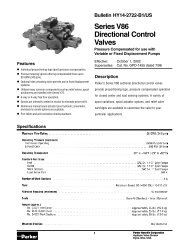
Catalogue HY17-8537/UKSpool Section<strong>Directional</strong> <strong>Control</strong> <strong>Valve</strong>s<strong>K220LS</strong>Spool section withPC spool actuatorCommon feed reducerMRM or MRC [75]Port relief valve, port B [76B]Port B [47]Port A [47]Port relief valve,port A [76A]Bleeder nippleSpool [69]Limiting of flow, Qset,QsetB [72]PC spool actuator [50]Bleeder nippleLimiting of flow, Qset,QsetA [72]Pilot pressure connection(P - B, A - T)Pilot pressure connection(P - A, B - T)Compensatordamping [67]Compensator [66]Spool section [45-89]The <strong>K220LS</strong> is a stackable directional valve and can be suppliedin combinations of 1 to 7 spool sections. Each section canbe equipped individually to incorporate a large number of differentfunctions. By means of function-adapted spools, spoolactuators, pressure relief valves, pressure compensators, etc.the valve can be optimized to suit different applications.PMTMConnections [04] and [47]The section service-port connections are the flange type accordingto SAE J 518. The fixing-screw threads are available intwo versions, UNC and M. Other connections on the section areof G type according to ISO 228/1 (for flat seal) or UN type accordingto SAE J 1926/1 (for O-ring seal). Please see page 3 fordimensions.MGMUUUFCSFCHFlanged connection with M threaded fixing screws.Other connections of G type.Flanged connection with M threaded fixing screws.Other connections of UN type.Flanged connection with UNC threaded fixing screws.Other connections of UN type.Spool section with service ports A and B according toSAE J518 Standard Pressure.Spool section with service ports A and B according toSAE J518 High Pressure.Mid-inlet section [90-99]In certain applications, e.g. the feeding of crawler-track motorson an excavator, there is a demand for high flow from two sectionsat the same time. This can be achieved by means of themid-inlet section Ml [90], which can be mounted anywhere inthe valve. Ideally, however, the high flows should be obtainedfrom the first and last spool sections, and the mid-inlet sectionshould be mounted between the last spool section and the endsection.Mid-inlet section with counter pressure valve.<strong>Valve</strong>s with mid-inlet sections can be fed with a pump flow of 2x 280 l/min. The mid-inlet section also contains two tank connectionsor, alternatively, one tank connection and a counterpressure valve (the same counter pressure valve that can beused in T2 [24].) There are two mounting plates on the mid-inletsection, one on each side. These should be used if the valve isto be mounted in any way other than with the service ports facingupward. See dimensional drawing on page 10.8 Parker HannifinMobile <strong>Control</strong>s DivisionBorås, Sweden