1947-1954 Truck - Custom IFS Kit - Total Cost Involved
1947-1954 Truck - Custom IFS Kit - Total Cost Involved 1947-1954 Truck - Custom IFS Kit - Total Cost Involved
- Page 2: ~ Custom IFS ~*’55-’59 Chevy pi
- Page 7 and 8: Install the ½-20 set screws into t
- Page 9 and 10: Centering the rack assembly:The rac
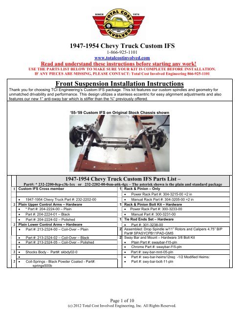
~ <strong>Custom</strong> <strong>IFS</strong> ~*’55-’59 Chevy pickup <strong>IFS</strong> shown**NOTE*The factory cross member should remain in place until the new cross member is fully welded inplace:Installing the boxing plates:Measure the width of the top and bottom of the rails.Cut or grind the longer lip back to make them both thesame width. This will allow installation of the boxingplate square to the frame.*NOTE* This picture is with the frame upside down.The boxing plate is tapered. Place the plate onto theframe within the corresponding taper/size.Page 2 of 10(c) 2012 <strong>Total</strong> <strong>Cost</strong> <strong>Involved</strong> Engineering, Inc. All Rights Reserved.
Installing the upper control arms:*NOTE* The acorn side of the 5/8” shaft facesforward.Place one washer onto the 5/8” control arm shaft andpush it through the front bushing of the control arm.Place a 2 nd washer behind the bushing and push the5/8” shaft into the front of the eccentric housing.*NOTE* Driver side control arm is picturedPlace the 3rd washer in between the bushing and theeccentric as shown.Push the 5/8” shaft all the way through the eccentricand bushing. You may need a little elbow grease toget the shaft all the way through.The 4 th and final washer can now be placed on the5/8” shaft and the Nylock can be installed.Torque to 75 ft lbsPage 6 of 10(c) 2012 <strong>Total</strong> <strong>Cost</strong> <strong>Involved</strong> Engineering, Inc. All Rights Reserved.
Install the ½-20 set screws into the Eccentric housingand tighten.Final alignment will be done once vehicle is finished.*’55-’59 Chevy pickup <strong>IFS</strong> shown*Installing the anti-sway bar:Slide the lock ring collar over the bar on each sidefirst. The split bushings go over the bar and then thealuminum blocks slide on over the bushings.The anti-sway bar mounts to the rear of the crossmember above the lower control arm pins. Use thesupplied hardware to install the aluminum blocksonto the cross member. Torque to 35 ft lbs.Center the anti-sway bar and lock down the setscrews against the bushings.Page 7 of 10(c) 2012 <strong>Total</strong> <strong>Cost</strong> <strong>Involved</strong> Engineering, Inc. All Rights Reserved.
Installing the Coil-overs:Place the top of the shock into the top mount on thecross member. The adjustment knob should befacing the rear of the vehicle.Use the ½” button head bolt and short nylock toattach the shock.*NOTE* Threaded side of the shock body goes downThe bottom bolt has a modified head that needs tobe installed from the front to the back.Installing the spindle assemblies:Place the spindle onto the lower ball joint with thesteering arm facing forward with the large I/D tie rodend taper facing down.(The tie rod end goes up intothe steering arm)Place the ball joint washer first and then the castlenut. Torque the lower ball joint to 90 ft. lbs and installthe cotter pin. The lower ball joint is a MOOG K719Pull the upper control arm down onto the spindle.Place the ball joint washer first and then the castlenut. Torque the lower ball joint to 70 ft. lbs andinstall the cotter pin. The upper ball joint is a MOOGK772*NOTE* Caliper Fittings:GM Calipers = 10mm x 1.5Wilwood Calipers = 1/8” NPTPage 8 of 10(c) 2012 <strong>Total</strong> <strong>Cost</strong> <strong>Involved</strong> Engineering, Inc. All Rights Reserved.
Centering the rack assembly:The rack needs to be centered to allow equalsteering left to right. On a bench, turn the pinion outto lock one way. Measure from a convenient point tothe end of the inner tie rod. (This rack was 17 ¾).Turn the pinion of the opposite lock position andmeasure from the same point to the end of the sametie rod (11 ¾). 17 ¾ minus 11 ¾ = 6. Divided by 2 =3 Add that number to the smallest measurement (11¾” + 3” = 14 ¾”) and turn the pinion back till you getthat measurement and your rack is centered.Installing the rack and pinion:Place the rack on the cross member brackets asshown. Use the supplied 5/8” hardware to fasten itinto place. The picture shows a power rack thatrequires a 5/8” spacer between the rack and themounting brackets. A manual rack bolts directly tothe mounting brackets not needing these spacers.Torque bolts to 90 ft. lbs*NOTE* Power Rack & Pinion fittings:9/16”-18 Pressure side & 5/8”-18 Return sideInstall the jam nut and outer tie rod end onto bothsides of the rack. With the rotors pointing straightahead(0 toe) install the tie rod ends into the bottomof the steering arm. Torque the tie rod ends to 60 ft.lbs. and install the cotter pin.*NOTE* Rack & Pinion output shaft:Manual rack = 9/16”-26 splinePower rack = ¾”-36 SplinePage 9 of 10(c) 2012 <strong>Total</strong> <strong>Cost</strong> <strong>Involved</strong> Engineering, Inc. All Rights Reserved.
The sway bar routes from behind the cross memberabove the lower control arms and hooks up to thefront of the control arms. Use the supplied hardwareto install the rod ends with the male on the bottom.*NOTE* You can adjust the preload(or lack thereof)once the vehicle is ready to be driven. To do this,disconnect one ½” bolt on any heim, place driver inthe driver’s seat, adjust the loose heim until it goesonto the anti-sway bar with zero load.Alignment specificationsCaster: Power rack 4-6 degrees positiveManual rack 2-4 degrees positiveCamber: 0 DegreeToe-in: 1/32 to 1/16 inchThe lower control arms should be level to the groundor within a degree or two once the vehicle is at fullweight. You can then perform the final alignment.AXLE STUD SIZES:4.5” Bolt circle rotors = ½”x20(’75-’80 Ford Granada)4.75” Bolt circle rotors = 12mmx1.5(’82-’87 Camaro)ALL Wilwood hubs = 7/16”x20*’55-’59 Chevy pickup <strong>IFS</strong> shown*No returns or exchanges without a RMA#.Packages must be inspected upon receipt & be reported within 10 days.If you are missing parts from your kit, TCI Engineering will send the missing parts via FedEx or U.S. mailground.Returned packages are subject to inspection before replacement/refund is given. (Some items will be subject to a15% restocking fee)Thank you for your business!Page 10 of 10(c) 2012 <strong>Total</strong> <strong>Cost</strong> <strong>Involved</strong> Engineering, Inc. All Rights Reserved.


