DNV 2.7-3 Portable Offshore Units - Kranteknisk Forening
DNV 2.7-3 Portable Offshore Units - Kranteknisk Forening
DNV 2.7-3 Portable Offshore Units - Kranteknisk Forening

Create successful ePaper yourself
Turn your PDF publications into a flip-book with our unique Google optimized e-Paper software.
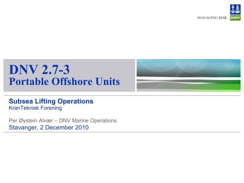
<strong>DNV</strong> <strong>2.7</strong>-3<strong>Portable</strong> <strong>Offshore</strong> <strong>Units</strong>Subsea Lifting OperationsKranTeknisk <strong>Forening</strong>Per Øystein Alvær – <strong>DNV</strong> Marine OperationsStavanger, 2 December 2010
Content of this Presentation• <strong>DNV</strong> Standard for Certification <strong>2.7</strong>-3, March 2011- Relationship <strong>DNV</strong> <strong>2.7</strong>-1 & <strong>DNV</strong> <strong>2.7</strong>-3- Define what is a <strong>DNV</strong> <strong>2.7</strong>-3 – <strong>Portable</strong> <strong>Offshore</strong> Unit?- Brief overview of content• Subsea use of PO <strong>Units</strong>- Design condition/loads- Considerations- Operational aspects• Design load calculations- Background for design factors- Example on how to calculate the lift design factor• Lift rigging design© Det Norske Veritas AS. All rights reserved 26 November 2010Slide 2
Relationship with <strong>DNV</strong> <strong>2.7</strong>-1The design of offshore containers are regulated through:IMO’s MSC/Circ.860 “Guidelines for the approval ofoffshore containers handled in open seas”Only offshore units/containers certified according to ‘<strong>DNV</strong>Standard for Certification <strong>2.7</strong>-1, <strong>Offshore</strong> Containers’ willautomatically fulfil the guidelines in MSC/Circ.860.<strong>DNV</strong> <strong>2.7</strong>-3 does not apply for units that are defined asoffshore containers. <strong>Offshore</strong> containers shall be designed,manufactured and certified according to <strong>DNV</strong> <strong>2.7</strong>-1.What is <strong>DNV</strong> <strong>2.7</strong>-3 if it is not an offshore container?© Det Norske Veritas AS. All rights reserved 26 November 2010Slide 3
Definition - PO <strong>Units</strong>• Definition in <strong>DNV</strong> <strong>2.7</strong>-3: A ‘PO Unit’ (<strong>Portable</strong> <strong>Offshore</strong> Unit) is apackage or unit intended for repeated or single offshore transportationand installation/lifting.• The maximum gross mass should normally not exceed 100 tonnes.• Could be lifted subsea!• 5 types defined:• Type A, skids arranged withcrash frames• Type B, skids without crashframes• Type C, no dedicated skidframe• Type D, stress skin design• Type E, generally defined© Det Norske Veritas AS. All rights reserved 26 November 2010Slide 4
Content in <strong>DNV</strong> <strong>2.7</strong>-3• GENERAL• Scope• Design & Operation• Definitions• Documents for acceptance andinformation• National authorities• References• CERTIFICATION PROCEDURES• Introduction• Design Verification• Certification testing and inspection• Summary of procedures• DESIGN• Design conditions• Materials• Operational Class• Analysis and Acceptance Criteria• Design Loads, Lifting & Impact• Sea Transport• Lifting Points• Design details• PO <strong>Units</strong> with tanks• Subsea application• MANUFACTURE• General• Materials• Welding & NDE• Secondary structure - Coating• Production documentation• TESTING• Extent -Lifting-Impact-Production• MARKING• Operational Class & Safety marking• Identification markings• Information plates• Additional information markings (optional)• LIFTING SETS• PERIODIC EXAMINATION, TESTS AND REPAIRS• General• Inspection, test and repairs on units• Appendix – Padeye design© Det Norske Veritas AS. All rights reserved 26 November 2010Slide 5
Test to Define Appropriate Design BasisTank for dangerous goods?IMDG Code + <strong>DNV</strong> <strong>2.7</strong>-1Container shaped & W
Procedure for Certification• Application sent to <strong>DNV</strong> (e.g. to vmo@dnv.com).• Order confirmed and fees agreed.• Drawings, documentation and calculations reviewed and approval givenby the approval office.• (Prototype) PO Unit manufactured under supervision of the Society'sSurveyor.• Unit tested according to (prototype) test requirements, witnessed by theSociety's Surveyor.• Production proceeds according to the agreed Quality Plan orManufacturing Survey Arrangement. Production tests according to list.• <strong>DNV</strong> surveyor issues <strong>Portable</strong> <strong>Offshore</strong> Unit Certificate (form 49.06a) andaffixes emblem.© Det Norske Veritas AS. All rights reserved 26 November 2010Slide 7
Materials and Manufacture• Design temperature, normally -20º C• Steel quality requirements• Aluminium and other materials• Welding Qualification• Inspection of Welds• Secondary structure• Production documentation© Det Norske Veritas AS. All rights reserved 26 November 2010Slide 8
Testing Requirements• All point lifting test- Mandatory, could be omitted for single transports- Test load mnimum of2.5 x MGW & FTest conclusion: Spreaderframe is required!• 2-point Lifting- Needed for R60, R45 & R60-SE- Test load minimum of:- 1.5 x MGW, and- 0.6 x F• Vertical Impact Test- Drop or lowering test- Could be substituted by calculationsless for MGW > 25tNOT PASSEDNOT PASSED© Det Norske Veritas AS. All rights reserved 26 November 2010Slide 9
Marking• Operational Class and Safety Marking<strong>DNV</strong> <strong>2.7</strong>-3 R45-Subsea-SEMGW = 16300 kgOPERATIONAL RESTRICTIONS• Identification by Certificate number• Information Plate- Type of PO Unit and Operational Class- Name of manufacturer.- Month/year of manufacture.- Maximum gross weight (kg)- ......- ......• Inspection Plate- ….- ….© Det Norske Veritas AS. All rights reserved 26 November 2010Slide 10
Content of this Presentation• <strong>DNV</strong> Standard for Certification <strong>2.7</strong>-3, March 2011- Relationship <strong>DNV</strong> <strong>2.7</strong>-1 & <strong>DNV</strong> <strong>2.7</strong>-3- Define what is a <strong>DNV</strong> <strong>2.7</strong>-3 – <strong>Portable</strong> <strong>Offshore</strong> Unit?- Brief overview of content• Subsea use of PO <strong>Units</strong>- Design condition/loads- Considerations- Operational aspects• Design load calculations- Background for design factors- Example on how to calculate the lift design factor• Lift rigging design© Det Norske Veritas AS. All rights reserved 26 November 2010Slide 11
Subsea – Design Condition• The effective weight of a PO Unit and the dynamic amplificationfactor will vary during a subsea lift. The calculation of maximumeffective weight shall include possible trapped water (when liftedout of water) and possible suction when lifted from the seabottom.• The worst realistic combination of effective and dynamicamplification shall be considered. Normally it is consideredadequate to use the following combination as basis for the designcondition:- DAF = 2.0- Submerged weight is 0.9 x MGW- General design factor = 1.4• The applied design condition always needs to be verified againstthe actual installation condition.© Det Norske Veritas AS. All rights reserved 26 November 2010Slide 12
Subsea – Design Factor, LiftThe following design requirement are included to cover subsea:• Design factor structure:F = 2. 5× MGWSub• Additional factor forpadeyes as for lift in air:1.2 and SKLIn order to ensure that the unit could be installed without too strictoperational limitations the drag area and volume, including addedvolume/mass should be reasonably limited.Hence <strong>DNV</strong> <strong>2.7</strong>-3 include the following guidance:A/Ws < 1.0V/Ws < 2.0where A is drag area and Ws is the submerged weightwhere V is the volume of the unit + added (water) mass© Det Norske Veritas AS. All rights reserved 26 November 2010Slide 13
Subsea – Design LoadsAdditional loads that should be considered for PO<strong>Units</strong> for subsea use:• Effect of horizontal wave loads. The tilt effect of this on the PO Unitcould normally be considered covered by the requirements in 3.5.• Local design for hydrodynamic loads, e.g. slamming loads.• Tugger points for horizontal and rotational control.• Guiding system for final positioning.• Retrieval loads.• Hydrostatic pressure.© Det Norske Veritas AS. All rights reserved 26 November 2010Slide 14
Design Considerations• Functional requirements, e.g. installation aids, as defined by contractspecifications, etc.• All air filled members shall be designed for the maximum hydrostaticpressure, or proper ventilation/water filling shall be ensured.• Lift points below CoG should normally be avoided.• Proper draining when lifted out of the water (if applicable).• Lift points should be placed/designed in such a way that the risk ofdamage and/or accidental release of rigging are neglectable.• Extended (more than a few days) subsea application of PO <strong>Units</strong> shouldbe specially evaluated and shall not be considered covered by the givenrequirements in this standard.© Det Norske Veritas AS. All rights reserved 26 November 2010Slide 15
Subsea – Operational Aspects• All assumed operational limitations shall be clearly indicated in the PO<strong>Units</strong> design documentation. Critical limitations should be indicated inthe certificate and normally marked on the PO Unit. Such limitationscould be:• Installation wave height/periods (if evaluated/applicable)• Special considerations, e.g. pass splash zone with inclination• Maximum water depth• Allowable loads on tugger points and guiding systems• Sling angles• The installation contractor needs to do a final assessment of theapplicable operation limitations based on the actual installation vesseland –procedure.• Installation means on the unit, e.g. as marking, ROV grab bars,tag/tugger line connection points, skids for monitoringsystems/equipment, should be installed as agreed.© Det Norske Veritas AS. All rights reserved 26 November 2010Slide 16
Content of this Presentation• <strong>DNV</strong> Standard for Certification <strong>2.7</strong>-3, March 2011- Relationship <strong>DNV</strong> <strong>2.7</strong>-1 & <strong>DNV</strong> <strong>2.7</strong>-3- Define what is a <strong>DNV</strong> <strong>2.7</strong>-3 – <strong>Portable</strong> <strong>Offshore</strong> Unit?- Brief overview of content• Subsea use of PO <strong>Units</strong>- Design condition/loads- Considerations- Operational aspects• Design load calculations- Background for design factors- Design factors• Lift rigging design© Det Norske Veritas AS. All rights reserved 26 November 2010Slide 17
Design Loads Lifting - Background• Based on <strong>2.7</strong>-1 and adjusted to new VMO Standard• Constant (with mass) design factor not considered adequate due to:- Rigging not mandatory, hence no direct influence on padeye design- Required minimum thicknesses reduced from <strong>2.7</strong>-3 June 2006- Full penetration welds not mandatory in <strong>2.7</strong>-3• Variation in operational limitations considered adequate due to:- PO <strong>Units</strong> could be many different design solutions- Normally PO <strong>Units</strong> do fulfil all the requirements in <strong>DNV</strong> <strong>2.7</strong>-1. to minimizehandling risk.- Weight variations greater than for <strong>DNV</strong> <strong>2.7</strong>-1 containers- Use frequency variations greater than for <strong>DNV</strong> <strong>2.7</strong>-1 containers• If offshore lift operational wave height limit has to be taken less than in<strong>DNV</strong> <strong>2.7</strong>-1 (i.e. Hs = 6.0 m) why not also reduce the design requirement?© Det Norske Veritas AS. All rights reserved 26 November 2010Slide 18
PO <strong>Units</strong> - Operational Class• PO <strong>Units</strong> shall be assigned to a Operational Classfor the offshore lift. The class should be selectedbased on the following:- Weight.- Risk evaluation.- Type of structure, A through E• Risk based on items as - Equipment specially sensitive toimpact loads - Out sticking parts - Lack of roof protection - Lift points inpositions where they could be damaged by impacts - Lack of propercrash framing and there is installed/ transported equipment that could bedamaged due to impacts - exceptionally geometry or unhandy (big) size- Lift rigging including (loose) spreader bar(s)© Det Norske Veritas AS. All rights reserved 26 November 2010Slide 19
Operational Classes• The following three Operational Classes with operational limitingsignificant wave height as indicated are used in this certificationnote for <strong>DNV</strong> <strong>2.7</strong>-3 PO <strong>Units</strong>:- Class R60 – Lift from/to vessel in max Hs = 6.0m- Class R45 – Lift from/to vessel in max Hs = 4.5m- Class R30 – Lift from/to vessel in max Hs = 3.0m• In addition the following notations will be used:- PO Unit for Subsea use: Subsea- PO Unit for single event/transport only: SE© Det Norske Veritas AS. All rights reserved 26 November 2010Slide 20
Safety Factor Calibration© Det Norske Veritas AS. All rights reserved 26 November 2010Slide 21
Design Requirements - Summary• Calculation Methods. Only the primary structure shall be included in thedesign calculations.• Allowable Stresses. Von Mises equivalent stresses, σ e = 0.85×C. For steel:C = Re = minimum yield stress.• Sea Transport loads- According to calculated accelerations or based on 1g• Design Lifting Loads:- All point lift structure- 2 point lift structure (for some structures)- Padeyes – all point lift (with SKL factor) only• Impact Loads:- Horizontal impact- Vertical impact (Drop test)- Minimum thicknesses• Welding- Red. factor: Fillet = 0.5, partial = 0.75 and full pen. = 1.0© Det Norske Veritas AS. All rights reserved 26 November 2010Slide 22
Design Loads – All points LiftingFor 2-point lift: 0.6 x F for the structure.© Det Norske Veritas AS. All rights reserved 26 November 2010Slide 23
Design Load – Lift Points• For 2-, 3- or 4 leg sling arrangements without spreader bars, the resultantsling force (RSF) on each padeye should be calculated based on thefollowing equation:RSF = 1.2 x SKL x PL x F / cos(γ)• γ = the angle between the sling leg and vertical.• SKL = Skew load factor due to sling length deviations. Could be taken as1.25 (assuming that sling lengths are adequately controlled) for a 4 slingsrigging and 1.1 for 2- and 3 slings riggings.• PL = Per cent Loading of F (quasi-static calculations) in the most loadedpadeye.© Det Norske Veritas AS. All rights reserved 26 November 2010Slide 24
Lift Point, Out-of-Plane Loads• Design angle between sling- andpadeye plate planes.• Inaccuracies in padeye fabrication andrigging design considered (e.g. due tohook size) causing an angle betweensling and padeye plate planes.• Angle difference between crane hoistline and the line from the hook centre tothe PO Unit CoG. This could be due to:- Inclined transport vessel deck during liftoff.- Not plumb hoist line during lift-off.- Horizontal loads on PO Unit from e.g.tugger lines and impacts.- If subsea PO Unit, horizontal loads fromwaves (and current).© Det Norske Veritas AS. All rights reserved 26 November 2010Slide 25
Appendix A - Padeyes• Equations given to check:- Bearing pressure- Tear out- Cheek plate weldsat the padeye hole• In addition- Combined stresshas to be checked for critical sectionsincluding connection to mainstructure© Det Norske Veritas AS. All rights reserved 26 November 2010Slide 26
Content of this Presentation• <strong>DNV</strong> Standard for Certification <strong>2.7</strong>-3, March 2011- Relationship <strong>DNV</strong> <strong>2.7</strong>-1 & <strong>DNV</strong> <strong>2.7</strong>-3- Define what is a <strong>DNV</strong> <strong>2.7</strong>-3 – <strong>Portable</strong> <strong>Offshore</strong> Unit?- Brief overview of content• Subsea use of PO <strong>Units</strong>- Design condition/loads- Considerations- Operational aspects• Design load calculations- Background for design factors- Design factors• Lift rigging design© Det Norske Veritas AS. All rights reserved 26 November 2010Slide 27
Slings & ShacklesFor Slings:MBL ≥ 1.6 x RSFTable 7-1 – Minimum Sling Diameter (D)Class Single event Multiple useR30 D ≥ 10 mm D ≥ 12 mmR45 D ≥ 12 mm D ≥ 15 mmR60 D ≥ 14 mm D ≥ 18 mmFor Shackles:WLL ≥ 0.4 x RSFand MBL min 5 x WLL© Det Norske Veritas AS. All rights reserved 26 November 2010Slide 28
© Det Norske Veritas AS. All rights reserved 26 November 2010Slide 29