MICROFICHE REFERENCE LIBFUUW - Cd3wd.com
MICROFICHE REFERENCE LIBFUUW - Cd3wd.com MICROFICHE REFERENCE LIBFUUW - Cd3wd.com
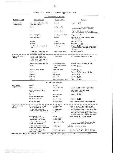
123an overall gear ratio of 1 to 120, increases the first driving gear’s lo-20rpm to a final 1200-2400 rpm which is usable for a centrifugal pump. Fora range of lifts from 3.3 ft to 7.5 ft, the small centrifugal used suppliedfrom 330 to 25 cfh, respectively. The use of worm gears and/or fewergears with higher ratios to reduce friction are among the recommendationsmade to increase efficiency. (A detailed description of this work isgiven in a 1967 thesisby Garg.)Table 5.1 outlines the basic motions which can be provided by manualpower and some of the typical water lifter/transmission combinationswith which they can be utilized.5.3 AnimalLike manual power, animals provide a relatively mobile source ofdriving energy which can be utilized for several duties, e.g., plowing,transportation, water lifting. Thus, if an animal can be used for tasksother than just water lifting, the price and maintenance costs of thatanimal can be tltime-shared’lby each task for economic purposes.Although draft animals constitute a common and vital source of powerin many developing countries, their upkeep can be particularly difficultin areas where water is scarce, rainfall is variable, or livestock diseaseis common (Merrill, 1976). If an operator does not want to, or cannot,provide for the care and feeding of an animal, or he only needs theanimal(s) for a short period of time, be can rent or lease the animals.In this case his prime movers cost for water lifting will be the rent(time-shared if used for other duties). However, when an operator awns hisown animal(s), he will have an initial purchase cost plus maintenance.Initial costs will vary greatly depending on the type, size, and conditionof the animal, and the geographic area.
Table 5.1Manual power appl icat i ansA. Rcciprocnt ina mot ionsPerformed wiCh \c’;rtrr l i ftrr-.-arms and/orupper torsoro:v (my n!so includepull”ys, MC.)roperoperopehandlehandlehnndlcrodand poleand poleand connrccingRcmerhshuchrt frfiurc 3.0swiiipuntcrbnskcchaI;1ncccountcrpoiscshovelliftmay require 50meI rg movcmcn: ; for ? personsfi~urr 3 .(j can also.opcratcWI th one person and counterweightfigure 3.3fi~urc .3.5 mav require some1 cp tnovcmcntflgurc3 ~ 7afigures 3.16fijiurc 3.1 acan also incorporatercw~tc~wcight or spring rerurndcviccscranh and rocher mccha- cent r i fuga I lwmjs see Carl: (1067)nism. tear train------------------------------------------------------lcps and IOUCP connt-zt ing rod, font 1’ i 9 ton purnllsee Schiolcr (19751, p. 10torso prd.al nnd rrlurn dc-vice (c..g., spring orcountcrwcipht) : -pedal and spring return d i nphrajim pump nd:ytation of figure 3. 16pedal air dinplaccmrnt figure 3.31pumprocking foot rests Iw I lows pump figure 3.15direct doons fiwrw 3.3a and ‘3.10arms and/orupper torsocrnnhIl. Circular morious---screwcrnnh wittrr laddercrank and small gear rotarytrainlcvcrsemi-rotar)crank and windlass huchctcrnnh nnd shaft ch:ii n pumpcrank and cam piston Iwmp-----------------------------~----legs and loucr horizontal axis trcad- paddle wheelto-so mill or pedals (on noriolifter or scperatc I’crriw wheelwith conocct ing shaft)’ tympanumhoriaoncal axist rrntlmi I I or pcda I sconncctcd via shafthnriront;tl nris Crcadmilland windlassscrewwater I;Mcrchn i n pumprope and hut hcthorizoiitnl axis trend- pi ston pumpmill (or pedals) and camhorixntal axis pedals cent r i fuga I pumpnnd ccar trnin1‘i~urcS. 18 small capacitiesLCC Cuhanhs (Igil),IladccI.cl (1930)fiwc 3.25andfigure 3.19utilircs ccccncric tvoe fearing--- -&--------------single unit (i.e., lifter andmi 11) cut transmission losses;SW Schiolcr (1!)75) pp. 5-G; for9t:lnding support, rcuui ro armrest as in figurc3.17 pedalingusually done in slttlng positionsee figure 3.25aas aboveneeds human abi I icy~11 turn and rcvcrsc rotationwith ccccntric gearSimilar to Cnrg’s (1967) device*Vertical axis mi I Is and pcd:~ls cnn bc t&cd, hut rcquirc pinion grnrs to cnuvrrt to vcrticnl rotation.
- Page 79 and 80: 72Table 3.3 records some of the per
- Page 81 and 82: 74Several names which are also appl
- Page 83 and 84: 76Table 3.5Zawafa performanceLiftDi
- Page 85 and 86: 78noria and the discharge and head
- Page 87 and 88: 80enclosed circumference can also b
- Page 89 and 90: 82Most early tympanums were of the
- Page 91 and 92: 84Table 3.6Tympanum performanceDiam
- Page 93 and 94: 86sufficiently compact and lightwei
- Page 95 and 96: 88of 3000 gpm or 5000 psig. Dependi
- Page 97 and 98: SE;vlI - ROTARYBUCKET VANEU’C)Fig
- Page 99 and 100: 92(a)AIRCHAMBERAIR FEEDERVALVEWASTE
- Page 101 and 102: 94Table 3.8Ram performanceA. Typica
- Page 103 and 104: COMPRESSEDAIRDEAofpctI5LT1EDUCTC II
- Page 105 and 106: 98FLASHTANK .iJI 10 -NON-RETURNVALV
- Page 107 and 108: Because the components are not yet
- Page 109 and 110: 102air-lift pumps. The oscillation
- Page 111 and 112: 104and from the impeller and confin
- Page 113 and 114: 106making this type pump useful for
- Page 115 and 116: 90s; 80iTi!g 700E 60W50SPECIFIC SPE
- Page 117 and 118: 110to lubricate all or some of thei
- Page 119 and 120: 112such variables as impeller size,
- Page 121 and 122: 114GEAR HEADOR IVE SHAFTTO PRIME MO
- Page 123 and 124: 116W(clFigure 4.6 (a) Thai-style ou
- Page 125 and 126: 118DRIVINGSUCTIONDIFFUSERa- - =tQ,E
- Page 127 and 128: DISCHARGELINE OISCHARGE RETURNLINEL
- Page 129: -122which at $.20/kg, cost $6.00. H
- Page 133 and 134: 126water lifting device. Animals ar
- Page 135 and 136: 1285.4.1 WindWindmills are currentl
- Page 137 and 138: 130even saw use on the windy plains
- Page 139 and 140: 172HAL F CYLINDERSt------TO WATER L
- Page 141 and 142: 135a vertical shaft, the wind will
- Page 143 and 144: --Table 5.3 Typical winchnil 1 clpp
- Page 145 and 146: Table 5.4 Typical watermill applica
- Page 147 and 148: 141MEDIUM BREASTFigure 5.6 (a) Medi
- Page 149 and 150: SLUICEGATEc, ~/I#/,.----- ------I L
- Page 151 and 152: 145-H-f -- WH---@II
- Page 153 and 154: 147with a 330,250 gpd capacity. Bat
- Page 155 and 156: 149Where electric power is not econ
- Page 157 and 158: 151electricity), the amount of use
- Page 159 and 160: 153of building and installing the d
- Page 161 and 162: 155II 300‘0083ooLoo93oo‘ootr000
- Page 163 and 164: 157Example G .l (after Molenaar, 19
- Page 165 and 166: LOW LIFT VERTICAL PUA /lPI------PER
- Page 167 and 168: Chapter 7Improvements and Research
- Page 169 and 170: 163example for further projects (Fa
- Page 171 and 172: 165Reynolds (1970) writes, " . ..ma
- Page 173 and 174: 16?BIBLIOGKAPlIYAddison, Ii., Ccntr
- Page 175 and 176: 169Committee on Water Supply Engine
- Page 177 and 178: Gatz, C. A., Johnston Vertical Pump
- Page 179 and 180: 173Mother Earth News,1574.Ilandbook
Table 5.1Manual power appl icat i ansA. Rcciprocnt ina mot ionsPerformed wiCh \c’;rtrr l i ftrr-.-arms and/orupper torsoro:v (my n!so includepull”ys, MC.)roperoperopehandlehandlehnndlcrodand poleand poleand connrccingRcmerhshuchrt frfiurc 3.0swiiipuntcrbnskcchaI;1ncccountcrpoiscshovelliftmay require 50meI rg movcmcn: ; for ? personsfi~urr 3 .(j can also.opcratcWI th one person and counterweightfigure 3.3fi~urc .3.5 mav require some1 cp tnovcmcntflgurc3 ~ 7afigures 3.16fijiurc 3.1 acan also incorporatercw~tc~wcight or spring rerurndcviccscranh and rocher mccha- cent r i fuga I lwmjs see Carl: (1067)nism. tear train------------------------------------------------------lcps and IOUCP connt-zt ing rod, font 1’ i 9 ton purnllsee Schiolcr (19751, p. 10torso prd.al nnd rrlurn dc-vice (c..g., spring orcountcrwcipht) : -pedal and spring return d i nphrajim pump nd:ytation of figure 3. 16pedal air dinplaccmrnt figure 3.31pumprocking foot rests Iw I lows pump figure 3.15direct doons fiwrw 3.3a and ‘3.10arms and/orupper torsocrnnhIl. Circular morious---screwcrnnh wittrr laddercrank and small gear rotarytrainlcvcrsemi-rotar)crank and windlass huchctcrnnh nnd shaft ch:ii n pumpcrank and cam piston Iwmp-----------------------------~----legs and loucr horizontal axis trcad- paddle wheelto-so mill or pedals (on noriolifter or scperatc I’crriw wheelwith conocct ing shaft)’ tympanumhoriaoncal axist rrntlmi I I or pcda I sconncctcd via shafthnriront;tl nris Crcadmilland windlassscrewwater I;Mcrchn i n pumprope and hut hcthorizoiitnl axis trend- pi ston pumpmill (or pedals) and camhorixntal axis pedals cent r i fuga I pumpnnd ccar trnin1‘i~urcS. 18 small capacitiesLCC Cuhanhs (Igil),IladccI.cl (1930)fiwc 3.25andfigure 3.19utilircs ccccncric tvoe fearing--- -&--------------single unit (i.e., lifter andmi 11) cut transmission losses;SW Schiolcr (1!)75) pp. 5-G; for9t:lnding support, rcuui ro armrest as in figurc3.17 pedalingusually done in slttlng positionsee figure 3.25aas aboveneeds human abi I icy~11 turn and rcvcrsc rotationwith ccccntric gearSimilar to Cnrg’s (1967) device*Vertical axis mi I Is and pcd:~ls cnn bc t&cd, hut rcquirc pinion grnrs to cnuvrrt to vcrticnl rotation.


