U-HN & U-HNH Series - Siemens Building Technologies
U-HN & U-HNH Series - Siemens Building Technologies
U-HN & U-HNH Series - Siemens Building Technologies

You also want an ePaper? Increase the reach of your titles
YUMPU automatically turns print PDFs into web optimized ePapers that Google loves.
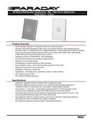
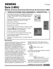
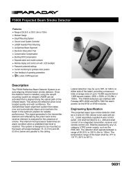
U-<strong>HN</strong> & U-<strong>HN</strong>H <strong>Series</strong>U-<strong>HN</strong> & U-<strong>HN</strong>H Electro-Mechanical Horns & Horn Strobes• Contactless Electro-Mechanical design, resultingin no contact generated inference and high reliability(Patent #5,596,477)• The Adapter/U-MCS feature offers four field selectablecandela values - 15/75, 30/75,75 or 110• Strobe operates in either sync or non-sync modes• Strobe only synchronization requires the Dual SyncControl Module or PAD-3• UL 1971 & UL 464 listed for both wall andceiling mountHorn• Horn/strobe can be wired together or independently• Screw Terminals accept #12 Awg.• Made in USA, ISO 9001 quality craftedHorn StrobeDescriptionThe Electro-Mechanical Horns & Horn Strobes combinestate of the art electronics with the rugged provendurability of a mechanical horn. The combination ofelectronics and mechanics provide the maximum penetratingsound power while eliminating problems associatedwith mechanical contacts. The Adapter/U-MCSfeature offers four field selectable candela settings -15/75, 30/75, 75 or 110.Detail – Adapterselector switchAll models remove the effects of inrush and RFI noiseassociated with contact operated mechanical devices.This design also eliminates the possibility of dust anddirt contaminating the contacts.The construction of the horn and horn strobe allows forflush mounting on a standard 4-inch square back box orsurface mounting on a Model FBX-S or FBX-SF.Screw terminals are provided for the horn and strobe.The strobe can be configured to operate independentlyfrom the horn. The strobe has a Xenon flashtubewith solid state circuitry for maximum reliabilityand efficiency, and a rounded dome shape made ofclear polycarbonate.Strobe Synchronization requires the Dual Sync Moduleor PAD-3.CATALOG NUMBER2567
Engineering SpecificationsThe audible/visual notification appliances shall be<strong>Siemens</strong> <strong>Building</strong> <strong>Technologies</strong>, Inc. Fire SafetyDivision <strong>Series</strong> U-<strong>HN</strong>-MCS, U-<strong>HN</strong>-MCS-C, U-<strong>HN</strong>H-MCS, or U-<strong>HN</strong>H-MCS-C Selectable Candela Strobe -Electron Mechanical Horn, or approved equal. Theaudible appliances shall be Fire Safety U-<strong>HN</strong>-C, U-<strong>HN</strong>,U-<strong>HN</strong>-W, U-<strong>HN</strong>H-C, or U-<strong>HN</strong>H, U-<strong>HN</strong>H-W ElectronMechanical Horns, or approved equal. The <strong>Series</strong>U-<strong>HN</strong>-MCS, U-<strong>HN</strong>-MCS-C, U-<strong>HN</strong>H-MCS, and U-<strong>HN</strong>H-MCS-C visual segment shall be the Adapter SelectableCandela Strobe and shall be listed to UL1971 (Standardfor Safety Signaling Devices for the Hearing Impaired).Audibles shall be UL listed under Standard 464 (FireProtective Signaling). In addition to indoor applications,the U-<strong>HN</strong>, U-<strong>HN</strong>-W and U-<strong>HN</strong>H, U-<strong>HN</strong>H-W, U-<strong>HN</strong>-MCS-WP and U-<strong>HN</strong>H-MCS-WP shall also be UL listed foroutdoor applications, when mounted in a Fire SafetyFWB-1 or FWB-2 Surface Box. All other appliances shallbe listed for indoor applications, and shall be ADA/NFPA/ANSI compliant. The strobe segment shall produce a flashrate of one (1) flash per second over the OperatingVoltage Range Limits. The strobe shall consist of a xenonflash tube enclosed in a rugged clear polycarbonate lens.The strobe shall be of a low current design, and shallprovide a minimum of four (4) field selectable strobeintensity settings,15/75, 30/75, 75, and 110 candela. All settings shall beUL1971 listed for both wall and ceiling mount applications.The selector switch shall be tamper resistant. Itshall not be necessary to remove the appliance fromthe mounting surface to select the strobe intensity.When strobe synchronization is required, the Strobeshall be compatible with the Fire Safety Dual SyncModule, or other source of Fire Safety Sync Protocol,and shall not drift out of synchronization. Inputs shallbe compatible with standard reverse polarity circuitsupervision by a Fire Safety Control Panel.The appliances shall combine electronics with therugged durability and maximum penetrating soundpower of a mechanical horn. To eliminate the effects ofinrush and RFI noise, the appliances shall not have anymechanical contacts.The <strong>Series</strong> U-<strong>HN</strong>-C, U-<strong>HN</strong>, U-<strong>HN</strong>-W, U-<strong>HN</strong>-MCS, andU-<strong>HN</strong>-MCS-C shall have a typical sound output ratingof 96dBA at 10 feet. The <strong>Series</strong> U-<strong>HN</strong>H-C, U-<strong>HN</strong>H,U-<strong>HN</strong>H-W, U-<strong>HN</strong>H-MCS, and U-<strong>HN</strong>H-MCS-C shallhave a typical sound output rating of 100dBA at10 feet.EnvironmentalIndoor: 32°F to 120°F (0°C to 49°C) at 85% RHWeatherproof (U-<strong>HN</strong>, U-<strong>HN</strong>-W & U-<strong>HN</strong>H, U-<strong>HN</strong>H-Wonly): -31°F to150°F (-35°C to 66°C) at 95% RHOperating Voltage Range LimitsStrobe: 16-32 Vdc or VFWRHorn: 16-32 Vdc or VFWRHorn Currentsee ordering information on page 3Typical dB Rating at 10 FeetU-<strong>HN</strong>-C, U-<strong>HN</strong>, U-<strong>HN</strong>-W, U-<strong>HN</strong>-MCS,U-<strong>HN</strong>-MCS-C 96dBU-<strong>HN</strong>H-C, U-<strong>HN</strong>H, U-<strong>HN</strong>H-W, U-<strong>HN</strong>H-MCS,U-<strong>HN</strong>HMCS-C: 100 dBNote: Typical dB ratings are frontal readings taken witha dB meter with signal mounted on wall.MountingFlush Indoor: 4" square boxSurface Indoor: FBX-S or FBX-SF boxWeatherproof (U-<strong>HN</strong>, U-<strong>HN</strong>-W & U-<strong>HN</strong>H, U-<strong>HN</strong>H-W,U-<strong>HN</strong>-MCS-WP and U-<strong>HN</strong>H-MCS-WP only): FWB-1orFWB-2 boxShipping WeightHorn: 1-1/2 lbs. approx.Horn/Strobe: 2 lbs. approx.DimensionsModelU-<strong>HN</strong>, U-<strong>HN</strong>-W &U-<strong>HN</strong>H, U-<strong>HN</strong>H-WModelU-<strong>HN</strong>-MCS &U-<strong>HN</strong>H-MCSThe <strong>Series</strong> U-<strong>HN</strong>, U-<strong>HN</strong>-W, U-<strong>HN</strong>-MCS, U-<strong>HN</strong>H,U-<strong>HN</strong>H-W, and U-<strong>HN</strong>H-MCS shall have a square grillefor mounting to a 4" square backbox, as well as <strong>Siemens</strong>Fire Safety FBX-S and FBX-F Surface Boxes.The <strong>Series</strong> U-<strong>HN</strong>-C, U-<strong>HN</strong>H-C, U-<strong>HN</strong>-MCS-C andU-<strong>HN</strong>H-MCS-C shall have a round grille for mountingto a 4" square backbox.ModelU-<strong>HN</strong>-C &U-<strong>HN</strong>H-CModelU-<strong>HN</strong>-MCS-C & U-<strong>HN</strong>H-MCS-C
Ordering InformationU-<strong>HN</strong> & U-<strong>HN</strong>H <strong>Series</strong> Horns Wall MountCanadian Ordering InformationCU-<strong>HN</strong> & C-U-<strong>HN</strong>H <strong>Series</strong> Horns Wall MountU-<strong>HN</strong> & U-<strong>HN</strong>H <strong>Series</strong> Horns Ceiling MountCU-<strong>HN</strong> & C-U-<strong>HN</strong>H <strong>Series</strong> Horns Ceiling MountU-<strong>HN</strong> & U-<strong>HN</strong>H <strong>Series</strong> Horn/StrobesCU-<strong>HN</strong> & C-U-<strong>HN</strong>H <strong>Series</strong> Horn/StrobesU-<strong>HN</strong> & U-<strong>HN</strong>H <strong>Series</strong> WeatherProof Horn/Strobes Wall MountCU-<strong>HN</strong> & C-U-<strong>HN</strong>H <strong>Series</strong> WeatherProof Horn/Strobes Wall MountListed operating range is 16 to 32 VDC/FWRMinimum UL measurements are 80.4-87.4dB taken in free air at 360°around the device and averaged. Typical readings are frontal soundreadings taken with a dB meter with signal mounted on wall. Rated forindoor use at 32°F to 120°F, (0°C to 49°C) with 85% RH. Outdoor, -31°Fto 150°F (-35°C to 66°C), RH at 95%.Note: For weather proof order part number FWB-1 or FWB-2 back box.
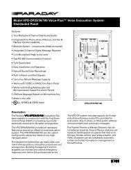
Ordering InformationU-<strong>HN</strong> & U-<strong>HN</strong>H <strong>Series</strong> 120Vac Horn/Strobes Wall Mount Non-Sync OnlyU-<strong>HN</strong> & U-<strong>HN</strong>H <strong>Series</strong> 120Vac Weather Proof Horn/Strobes Wall MountAccessoriesFor U-<strong>HN</strong> and U-<strong>HN</strong>H <strong>Series</strong> Electro-MechanicalHorns Wiring Diagram, please refer to InstallationInstruction Sheet.
Wiring Diagram
<strong>Siemens</strong> <strong>Building</strong> <strong>Technologies</strong>Fire SafetyFire Safety8 Fernwood RoadFlorham Park, NJ 07932Tel: (973) 593-2600FAX: (973) 593-6670Website: www.sbt.siemens.com/fis1/065MSFS-IGPrinted in U.S.A.Fire Safety2 Kenview BoulevardBrampton, OntarioCanada L6T 5E4Tel: (905) 799-9937FAX: (905) 799-9858January 2006New Issue