You also want an ePaper? Increase the reach of your titles
YUMPU automatically turns print PDFs into web optimized ePapers that Google loves.
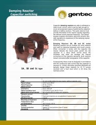
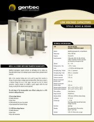
‣ Technical Data DS1 00 SeriesStandard Features Series I Series IIEnclosure floor mounted (Type 1, 2, 3R) 1, 2, 12 1, 2, 12Light biege ( other color on request ) • •Incoming silver Flashed Copper Bus 30 kV BIL c/w mechanical lugs • •Top or bottom Cable entry • •Capacitors space / KVAR max / Unit (Custom Staging Ratios) 1, 2, 4 1, 2, 4Power and Control wires T90 / T105 T90 / T105DSHI Capacitor (Heavy Duty type on request) • •Current limiting fuses HRC type ____ Amp. 200 ka • •Detuned reactor c/w thermal detection device • •Optional (s)Main Breaker or Fuses Disconnect O OBlown fuses indicating light c/w push bottom test O OMain current metering c/w Ammeter and phase selector O OKirk Key system interlock with the remote main breaker O OSpecial Metering Arrangement O ODisconnect switches interlocked with doors and main supply O OMagnetic Contactor O •Power Quality Meter O O• = StandardO = Optional‣ Technical ApplicationIf harmonic filters are being considered only for the purpose of power factor correction, then a de-tuned filter bank is the best choice. This filterwill do little for removing any harmonic distortion present on the system but will allow the installation of a large capacitor bank without anyadverse system interactions. De-tuned filter banks are less costly and are more reliable than partially de-tuned and tuned filter banks. The antiresonantfrequency should be considered to assure that it does not fall near the 3 rd harmonic.• DriveSaverWhen the resonant frequency of the <strong>series</strong> resonant filter circuit is tuned to a frequency lower than the harmonic occurring in the system, thefilter circuit is termed as detuned filter. The philosophy of the detuned filters would be clear from the following example.The harmonics that would be generated are 5 th , 7 th , 11 th and 13 th and so on. The lowest harmonic frequency which would occur in the system isthe fifth harmonic i.e. 300 Hz. If the <strong>series</strong> resonant circuit is tuned to a frequency of 245 Hz, then at all the harmonic frequencies the filter actsas an inductive component and the possibility of resonance at the fifth harmonic is eliminated.The impedance offered to the 5 th harmonic signal is less than the capacitor alone. This means that the <strong>series</strong> resonant filter will absorb the 5 thharmonic to a certain extent.The reactor to capacitance ratio p(%) reflects the ratio of reactor reactance to capacitor reactance at fundamental frequency. The resonantfrequency of the <strong>series</strong> resonant filter circuit is indicated indirectly by p. The following table shows a comparison for various reactor/capacitorcombinations at fundamental frequency of 60 Hz.ResonanceFrequencyFrRelativeResonance227 3.8 7.0245 4.1 6.0252 4.2 5.67282 4.7 4.52288 4.8 4.33300 5.0 4.0Reactor/CapacitorFactor: pPage 2 of 4
Motor <strong>DS100</strong> Series Options Auto FixedHPBasicPart. #SystemVoltageMotorHPTunedFilterReactivePowerType1, 12SeriesI or IIFuses3 PhInd. light480 V. + -- Suffix Suffix Suffix Suffix Suffix Suffix Suffix Suffix Fig.# Fig.#40 <strong>DS100</strong> 480 25 4.1 17 1 I F BFI 3 350 <strong>DS100</strong> 480 30 4.1 20 1 I F BFI 3 360 <strong>DS100</strong> 480 40 4.1 20 1 I F BFI 3 375 <strong>DS100</strong> 480 50 4.1 34 1 I F BFI 3 3100 <strong>DS100</strong> 480 60 4.1 40 1 I F BFI 3 3125 <strong>DS100</strong> 480 75 4.1 50 1 I F BFI 3 3150 <strong>DS100</strong> 480 100 4.1 67 1 I F BFI 3 3200 <strong>DS100</strong> 480 125 4.1 80 1 I F BFI 4 4250 <strong>DS100</strong> 480 150 4.1 101 1 I F BFI 4 4300 <strong>DS100</strong> 480 200 7.1 117 1 II F BFI 4 4350 <strong>DS100</strong> 480 250 4.1 134 1 II F BFI 4 4400 <strong>DS100</strong> 480 300 4.1 134 1 II F BFI 4 4450 <strong>DS100</strong> 480 350 4.1 151 1 II F BFI 5 5500 <strong>DS100</strong> 480 400 4.1 188 1 II F BFI 5 5600 <strong>DS100</strong> 480 500 4.1 201 1 II F BFI 5 5800 <strong>DS100</strong> 480 600 4.1 268 1 II F BFI 5 5900 <strong>DS100</strong> 480 800 4.1 308 1 II F BFI 5 51000 <strong>DS100</strong> 480 1000 4.1 II F BFI 5 5SeriesIISeriesIMotor <strong>DS100</strong> Series Options Auto FixedHPBasicPart. #SystemVoltageMotorHPTunedFilterReactivePowerType1, 12SeriesI or IIFuses3 PhInd. light600 V. + -- Suffix Suffix Suffix Suffix Suffix Suffix Suffix Suffix Fig.# Fig.#40 <strong>DS100</strong> 600 25 4.1 17 1 Ii F BFI 3 350 <strong>DS100</strong> 600 30 4.1 20 1 I F BFI 3 360 <strong>DS100</strong> 600 40 4.1 20 1 I F BFI 3 375 <strong>DS100</strong> 600 50 4.1 34 1 I F BFI 3 3100 <strong>DS100</strong> 600 60 4.1 40 1 I F BFI 3 3125 <strong>DS100</strong> 600 75 4.1 50 1 I F BFI 3 3150 <strong>DS100</strong> 600 100 4.1 67 1 I F BFI 3 3200 <strong>DS100</strong> 600 125 4.1 80 1 I F BFI 3 3250 <strong>DS100</strong> 600 150 4.1 101 1 I F BFI 3 3300 <strong>DS100</strong> 600 200 7.1 117 1 II F BFI 3 4350 <strong>DS100</strong> 600 250 4.1 134 1 II F BFI 3 4400 <strong>DS100</strong> 600 300 4.1 134 1 II F BFI 3 4450 <strong>DS100</strong> 600 350 4.1 151 1 II F BFI 3 4500 <strong>DS100</strong> 600 400 4.1 188 1 II F BFI 3 4600 <strong>DS100</strong> 600 500 4.1 201 1 II F BFI 3 4800 <strong>DS100</strong> 600 600 4.1 268 1 II F BFI 5 5900 <strong>DS100</strong> 600 800 4.1 1 II F BFI 5 51000 <strong>DS100</strong> 600 1000 4.1 1 II F BFI 5 5Model 1 2 3 4 5 6 7 8No … <strong>DS100</strong> 600 1000 5 1 B BFISeriesIISeriesIPage 3 of 4
Series I <strong>DS100</strong> Series IIFig.: 1 Fig.: 2.Series I <strong>DS100</strong> Series IIFig. 3 Fig. 4