Irtaza Askari, Syed Ali Hassan, M. Salman Fareed, Khalid Munawar ...
Irtaza Askari, Syed Ali Hassan, M. Salman Fareed, Khalid Munawar ...
Irtaza Askari, Syed Ali Hassan, M. Salman Fareed, Khalid Munawar ...

Create successful ePaper yourself
Turn your PDF publications into a flip-book with our unique Google optimized e-Paper software.
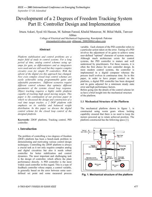
IEEE --- 2005 International Conference on Emerging TechnologiesSeptember 17-18, Islamabad<strong>Irtaza</strong> <strong>Askari</strong>, <strong>Syed</strong> <strong>Ali</strong> <strong>Hassan</strong>, M. <strong>Salman</strong> <strong>Fareed</strong>, <strong>Khalid</strong> <strong>Munawar</strong>, M. Bilial Malik, TanveerAbbasCollege of Electrical and Mechanical Engineering. Rawalpindi. Pakistanirtazaaskari@yahoo.com, alihassan_20002000@yahoo.comAbstractPlatform stabilization and control problems are amajor field of study in control systems. For a longperiod of time, analog control schemes using opampsfor gain, as differentiators and as integratorswere used and are still used but they require complexcircuitry even for simple PI controllers. With theadvent of the digital era this approach has changed.Now even complex closed loop control schemes areeasily achievable using programmable gains andadjustable parameters. Different scenarios requiredifferent control schemes that optimize differentparameters of the systems closed loop response.Object tracking requires a highly stable platformcapable of tracking high speed moving targets. Thispaper is the continuation of our previous paper inwhich we discussed the design and construction of areal time target tracker, a 2 DOF platform withemphasis on its stability and balanced weightdistribution. In this paper we discuss the digitalcontrol scheme for the closed loop control of thedesigned platform.Keywords: 2DOF platform, Tracking control, PIDcontroller.variable. Each element of the PID controller refers toa particular action taken on the error. Tuning of a PIDinvolves the adjustment of its gains to achieve someuser-defined "optimal" character of system response.Although much architecture exists for controlsystems, the PID controller is mature and wellunderstood by practitioners. For these reasons, it isoften the first choice for new controller design. Inmost modern control systems, the controller isimplemented in a digital computer whereas theprocess itself evolves in continuous time. So in thispaper, in order to have proper control on theplatform, a digital PID controller has been designedand its gains adjusted for a minimum steady stateerror and high performance factors.Before going into the details of the control scheme letus have a brief insight into the mechanical structureof the platform.1.1 Mechanical Structure of the PlatformThe mechanical platform shown in figure 1, isconstructed using worm gears whose lockingcapability ensured that there is no need to keep themotors powered up to retain achieved position. Theplatform constructed has the following specs [1].1. IntroductionThe problem of controlling a two degrees of freedom(DOF) platform has been a bench-mark problem indemonstrating and motivating various control designtechniques. Controlling the 2DOF platform is alwaysa crucial task as it not only requires complex analogand digital circuitries but also it needs robustcontroller for better stabilization and controldynamics. The most important and challenging taskis the design of controller, which affects the plantperformance directly. A PID controller is the mostwidely used controller in this regard. This is a type offeedback controller whose output, a control variable,is generally based on the error between some userdefinedset point and some measured processFig. 1. Mechanical structure of the platform0-7803-9247-7/05/$20.00 ©2005 IEEE477
IEEE --- 2005 International Conference on Emerging TechnologiesSeptember 17-18, IslamabadThe structure shown in figure 1 is constructed havinggear ratios of 70:1 in both the elevation and theazimuth, two DC servo motors with a torque of0.91Nm and speed of 2100rpm, having encoders ofhigh resolution 1250 counts/rev are used to drive theplatform. This construction enabled us to achieve alarge open loop torque of 62Nm to drive theplatform, enabling acceleration up to 1400rad/sec 2 atthe rated current. By keeping the motors at the staticbase the dynamic part of the platform was kept lightto meet the specs, however cost was paid in the formof mechanical coupling between the joints. Hence thekinematics of the platform are not straight forward.However this problem can be resolved with a propercontrol algorithm.Where θ Ε and θ Α are the outputs angles forelevation and azimuth respectively.2. Digital Control SchemeThe control loop can be divided into two parts. Oneportion of the control loop is in digital domain, whichis comprised of a computer and microcontrollersection. The other part of the loop is in continuousdomain, which comprises the H-Bridge for motordrives and the platform itself.Digital WorldAnalog World1.2 Platform KinematicsR +EG c (z)G(s)The PlatformC(s)Since the elevation shaft passes through the azimuthshaft so a rotation in azimuth introduces relativemotion in the elevation shaft in the oppositedirection. Hence open loop input to azimuth causesmotion at the output in both the axis, therebyintroducing coupling between the output elevationand the input to the azimuth. Taking this fact intoaccount the kinematics of the system can be given bythe following equation.⎡θ⎤ ⎡1/ N N / N ⎤⎡τ⎤=E1 2 1 E⎢θ⎥ ⎢A0 1/ N⎥⎢2τ⎥⎣ ⎦ ⎣ ⎦⎣ A⎦N1= Gear ratio for ElevationN2= Gear ratio for AzimuthτE= Torque applied to elevation platformτA= Torque applied to azimuth platform-H(z)Fig. 2. Elementary Feedback Control SystemAs shown in figure 3, the reference input applied tothe control scheme is the applied torque, which isapplied to platform using the RS 232 Serial portcommand to the microcontroller. The input is appliedin terms of the desired angle [2]. The desired input inturn actuates the plant. The output from the plant isfed back, the output and the reference input are usedto calculate the error. This error drives the plant. Asthe plant output approaches the desired output theerror reduces thereby reducing the platform drive,eventually the platform comes to rest close to thedesired position.Reference I/Pfrom the PC’sSerial Port+-P Gain++PWM+ I Gain +H-BridgeGenerationPlantOutputPIC 17C44 MicrocontrolerShaftDecoderFig. 3. Control scheme for the 2DOF Platform478
IEEE --- 2005 International Conference on Emerging TechnologiesSeptember 17-18, IslamabadThe microcontroller communicates with the PCthrough its serial port, similarly all the error and drivecalculations are performed in the microcontroller; theresulting PWM drives the motors of the platform.The shaft decoder ICs reads the readings of the shaftencoders mounted on the motors. The microcontrolleruses the output of the shaft decoder ICs to calculatethe respective error that drives the motors.output response is examined. The following figuresshow the results of experimentation:Figure 4 shows that the steady state error is very lowand settling time is fast. This type of gain can be usedin tracking purposes.3. Gain Selection ProcedureDue to the coupled joints of the system the elevationoutput had to be decoupled from the azimuth input,hence the elevation gains were adjusted first.A simple digital implementation of a PID controller,is as follows [3]:P = KekPkk∑I = KT ek i tt=0Dk = ( Kd / T)( ek −ek−1)CVk = Pk + Ik + DkWhere e k = SP k – PV k , , CV is the control variable,SP is user defined set point, PV is measured processvariable and T is the sampling interval. Anotherimportant aspect in sampled data control systems isthe choice of sampling intervals. With electroniccontrollers that emulate continuous time algorithms,this choice is simple: sample as fast as possible. Thisis because of the approximations that are used togenerate the difference equations describing thecontrollers. Smaller sampling intervals mean that theproperties of the underlying controller design will beless distorted, hence more predictable and betterperformances.Extensive experimentation was carried out withdifferent gains so as to achieve the desired closedloop response. First keeping I and D gains zero, the Pgain was adjusted to a point where it resulted inminimum steady state error. Increasing the P gainfurther would induce oscillations, which isundesirable.Keeping this P gain, the I gain was adjusted toeliminate the steady state error.With these gains we achieved the desired results.Similarly for the azimuth the same procedure resultedin these gains.3.1. Controller gains for ElevationFig. 4. Input output plot for P=1.5Increasing the gain to 1.8 have almost same steadystate error but high rise time and also low settlingtime.Fig. 5. Input output plot for P=1.8Increasing gain causes oscillations as can be seenfrom figure 6. If gain is further increased theoscillations continue to increase in the output so thisis the ending point for the proportional gain. Sincethe platform is used for tracking purpose, thereforeoscillations will cause error to grow up.As described above the proportional gain is appliedfirst. A step input is given to the system and the479
IEEE --- 2005 International Conference on Emerging TechnologiesSeptember 17-18, Islamabad3.2. Controller Gains for AzimuthSame step input applied to azimuth platform showsfollowing results: A very small ideal steady stateerror and low settling time is observed for aproportional gain of 1.5 as shown in figure 9.Fig. 6. Input output plot for P=2By applying proportional gain with the integral gain,rise time is high but there appears an overshoot of 1.2degrees but steady state error is almost zero as shownin figure 7.Fig. 9. Input output plot for P=1.5Increasing gain increases steady state errorFig. 7. Input output plot for P=1.8 and I=0.1Increasing I gain causes the overshoot to rise moreFig. 10. Input output plot for P=1.9Increasing more proportional gain causes oscillationsFig. 8. Input output plot for P=1.8 and I=0.2Fig. 11. Input output plot for P=2480
IEEE --- 2005 International Conference on Emerging TechnologiesSeptember 17-18, IslamabadIncreasing more proportional gain causes oscillationsI and P gains for azimuth don’t cause a suitableoutput as overshoot becomes high and steady stateerror does not settle to a value.The platform had to achieve the specified positionbefore the next frame was captured. This required asmall rise time for the system however any overshoot or oscillation in the platform output will makethe net system unstable as the next reference will bebased on the image captured. If it was captured on theovershoot the next reference might be faulty therebycausing a loss of target. The following gains wereselected.Elevation : P=1.5Azimuth : P=1.55. Conclusions and RecommendationsFig. 12. Input output plot for P=1.5 I=0.14. Mode of OperationFor the control of the platform in different scenariostwo modes of operation were selected. Theinformation of the mode was conveyed to themicrocontroller through the serial port for which asecure communication protocol was used. Thisprotocol transmits the mode of operation, thereference input for the azimuth and elevation, theparity for alignment of the data packet and achecksum in the last bytes to ensure error freetransmission. The following modes wereprogrammed in the microcontroller.Excellent results were achieved for the static targettracking. For the moving target tracking, littleoscillations were observed in the azimuth, this wasdue to backlash in the gears driving the platform.This effect is not visible in the elevation as thegravitational force ensured that the output and theinput remained in contact.5.1. Experimental verificationTo verify the results and to confirm the effect ofbacklash, the following experiment was carried out.Placing two objects exactly apart 90 0 , the platformwas placed facing the first object and a reference of90 0 was applied to the platform. The platformachieved the reference with a very little error i.e.89.5 0 instead of the reference 90 0 ..Position I4.1. Static Target TrackingIn this mode the aim was to achieve a desiredposition from the starting positions the reference withminimum steady state error so the following gainswere fixed in the microcontroller using aboveexperimentation for this mode.Elevation: P=1.8 and I=0.1Azimuth : P=1.54.2. Moving Target TrackingIn this mode the aim was to track a target in the nextframe, taking center of the screen as a reference. Theimage processing algorithms running on thecomputer calculated the future position of the targetwhich served as the reference to the control scheme.Position II90 0Camera mounted onPlatformFig. 13. Position sensing experimentThis effect is also prominent in the PI graph of figure14. As at the point of directional reversal the drivingand the driven gears are decoupled so the motor isrunning free. There is a sharp direction reversal asthere is no load on the motor, instead of the expected481
IEEE --- 2005 International Conference on Emerging TechnologiesSeptember 17-18, Islamabadsmooth settling of the curve.Past, Present and Future of PID Control, pp.91-96,2000.[8] M. Araki and H. Taguchi, “Two-degree-offreedom PID controllers,” Systems, Control andInformation, vol. 42, pp. 18-25, 1998.Fig. 14. Input output plot for a step input andPI gainsAs evident from the preceding discussion there isbacklash in the system that is causing jittery trackingin the azimuth therefore some backlash compensationshould be used for the azimuth drive. To achievebetter tracking the shaft encoder should be mountedon the final output.A model-based controller accommodatingintermediate states would be a better choice ascompared to the PID.Reference:[1]Tanveer Abbas, M. Yasir Khan, “Development ofa 2DOF Tracking System, Part I: Design andFabrication of the platform” (submitted forpublication in ICET 2005)[2] Raymond T. Stefani, Bahram Shahian, Clement J.Savant, Gene H. Hostetter, Design of FeedbackControl Systems. Oxford University Press; 4thedition.[3]M. Tham, “Discretised PID Controllers” Part of aset of study notes on Digital control. University ofNewCastle.[4] Graham C. Goodwin, Stefan F. Graebe, Mario E.Salgado, Control System Design.[5] M. Araki, “Two-degree-of-freedom controlsystem:part I,” Systems and Control, vol. 29, pp.649-656, 1985.[6] K. Hiroi, A. Nomura, A. Yoneya, and Y. Togari,“Advanced two-degree-of-freedom PID algorithm,”Proc. 29th SICE Annual Conference, pp.49-50, 1990.[7] H. Taguchi and M. Araki, “Two-degree-offreedom PID controllers: Their functions and optimaltuning,” Proc. IFAC Workshop on Digital Control:482