PILE FOUNDATIONS - Gnpgeo.com.my
PILE FOUNDATIONS - Gnpgeo.com.my
PILE FOUNDATIONS - Gnpgeo.com.my

You also want an ePaper? Increase the reach of your titles
YUMPU automatically turns print PDFs into web optimized ePapers that Google loves.
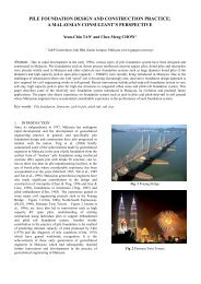
<strong>PILE</strong>D FOUNDATIONDESIGN & CONSTRUCTIONBy Ir. Dr. Gue See Sew &Ir. Chow Chee Menghttp://www.gnpgeo.<strong>com</strong>.<strong>my</strong>
Contents• Overview• Preliminary Study• Site Visit & SI Planning• Pile Design• Pile Installation Methods• Types of Piles
Contents (Cont’d)• Piling Supervision• Pile Damage• Piling Problems• Typical Design and Construction Issues• Myths in Piling• Case Histories• Conclusions
Overview
What is a Pile FoundationIt is a foundation system thattransfers loads to a deeperand <strong>com</strong>petent soil layer.
When To Use Pile Foundations• Inadequate Bearing Capacity of ShallowFoundations• To Prevent Uplift Forces• To Reduce Excessive Settlement
<strong>PILE</strong> CLASSIFICATION• Friction Pile– Load Bearing Resistance derived mainlyfrom skin friction• End Bearing Pile– Load Bearing Resistance derived mainlyfrom base
Overburden Soil LayerFriction Pile
End Bearing PileOverburden SoilRock / Hard Layer
Preliminary Study
Preliminary Study• Type & Requirements of Superstructure• Proposed Platform Level (ie CUT or FILL)• Geology of Area• Previous Data or Case Histories• Subsurface Investigation Planning• Selection of Types & Size of Piles
Previous Data & CaseHistoriesExistingDevelopmentAProposedDevelopmentExistingDevelopmentBOnly Need MinimalNumber of BoreholesBedrockProfile
Challenge The Norm ThruInnovation To Excel
SELECTION OF <strong>PILE</strong>SFactors Influencing Pile Selection– Types of Piles Available in Market (see Fig. 1)– Installation Method– Contractual Requirements– Ground Conditions (eg Limestone, etc)– Site Conditions & Constraints (eg Accessibility)– Type and Magnitude of Loading– Development Program & Cost– etc
TYPE OF <strong>PILE</strong>SDISPLACEMENT <strong>PILE</strong>SNON-DISPLACEMENT <strong>PILE</strong>STOTALLY PREFORMED <strong>PILE</strong>S(A ready-made pile is driven or jackedinto the ground)DRIVEN CAST IN-PLACE <strong>PILE</strong>S(a tube is driven into ground toform void)Bored pilesMicro pilesHollowSmall displacementSolidConcrete TubeSteel TubeSteel PipeConcrete Spun PilesClosed endedtube concretedwith tube left inpositionClosed ended tubeOpen ended tubeextracted whileconcreting (Franki)ConcreteSteel H-piles(small displacement)Bakau pilesTreated timber pileRestricted use due toenvironmentalconsiderationsPrecast R.C.pilesPrecast prestressedpilesFIG 1: CLASSIFICATION OF <strong>PILE</strong>S
PREFORMED <strong>PILE</strong>SLEGEND :GEOTECHNICALSCALE OF LOAD(STRUCTURAL)BEARING TYPETYPE OFBEARINGLAYERUNIT COSTTYPE OF INTERMEDIATE LAYERGROUNDWATERENVIRONMENTDESIGNCONSIDERATIONSBAKAU <strong>PILE</strong>STIMPER <strong>PILE</strong>SRC <strong>PILE</strong>SPSC <strong>PILE</strong>SSPUN <strong>PILE</strong>S10000 x x ? a a a a x a ? x 70%)x x ? ? ? a a ? a a ?DENSE / VERY DENSE SANDx ? a a a a a a a a aSOFT SPT < 4a a a a a a a a a ? aCOHESIVE SOILM. STIFF SPT = 4 - 15 a a a a a a a a a a aV. STIFF SPT = 15 - 32 ? a a a a a a a a a aHARD SPT > 32x ? a a a a a a a a aLOOSE SPT < 10COHESIVELESS SOILSOIL WITH SOME BOULDERS /COBBLES (S=SIZE)ABOVE <strong>PILE</strong> CAPBELOW <strong>PILE</strong> CAPTYPE OF <strong>PILE</strong>M. DENSE SPT = 10 - 30NOISE + VIBRATION; COUNTER MEASURESREQUIREDSTEEL H <strong>PILE</strong>Sa a a a a a a a a a a? a a a a a a a a a aDENSE SPT = 30 - 50 x ? a a a a a a a a aV. DENSE SPT > 50 x x a a a a a ? a a ?S < 100 mm x ? a a a a a a a a ?100-1000mm x x ? ? ? a a ? a a x1000-3000mm x x ? ? ? ? ? ? ? a x>3000mm x x ? ? ? ? ? ? ? a xa a a a a a a a a a ax a a a a a a a a a aa a ? ? ? ? ? a a a aPREVENTION OF EFFECTS ON ADJOINING? ? ? ? ? ? ? a ? a aSTRUCTURES(SUPPLY & INSTALL) RM/TON/M 0.5-2.5 0.3-2.01.0-3.5 1-2 0.5-2 1.5-3 1-2.5STEEL PIPE <strong>PILE</strong>SJACKED <strong>PILE</strong>SBORED <strong>PILE</strong>SMICRO<strong>PILE</strong>SAUGERED <strong>PILE</strong>S8x?INDICATES THAT THE <strong>PILE</strong> TYPE ISSUITABLEINDICATES THAT THE <strong>PILE</strong> TYPE ISNOT SUITABLEINDICATES THAT THE USE OF <strong>PILE</strong>TYPE IS DOUBTFUL OR NOT COSTEFFECTIVE UNLESS ADDITIONALMEASURES TAKENFIG 2 : <strong>PILE</strong> SELECTION CHART
Site Visit and SI Planning
Site VisitThings To Look For …• Accessibility & Constraints of Site• Adjacent Structures/Slopes, Rivers,Boulders, etc• Adjacent Activities (eg excavation)• Confirm Topography & Site Conditions• Any Other Observations that may affectDesign and Construction of Foundation
Subsurface Investigation (SI)Planning• Provide Sufficient Boreholes to get Subsoil Profile• Collect Rock Samples for Strength Tests (eg UCT)• In-Situ Tests to get consistency of ground (eg SPT)• Classification Tests to Determine Soil TypeProfile• Soil Strength Tests (eg CIU)• Chemical Tests (eg Chlorine, Sulphate, etc)
Typical Cross-Section at Hill SiteHard Material LevelGround LevelVery Hard Material LevelBedrock LevelGroundwater Level
CROSS SECTIONBHEXISTINGGROUNDLEVELBHC’ 1, ø’ 1BHPerched WTClayey LayerC’ 2, ø’ 2SeepageC’ 3, ø’ 3Water Table
Placing Boreholes in LimestoneAreas• Stage 1 : Preliminary S.I.- Carry out geophysical survey (for large areas)• Stage 2: Detailed S.I.- Boreholes at Critical Areas Interpreted fromStage 1• Stage 3: During Construction- Rock Probing at Selected Columns tosupplement Stage 2
Pile Design
<strong>PILE</strong> DESIGNAllowable Pile Capacity is the minimum of :1) Allowable Structural Capacity2) Allowable Geotechnical Capacitya. Negative Skin Frictionb. Settlement Control
<strong>PILE</strong> DESIGNStructural consideration• Not overstressed during handling, installation & inservice for pile body, pile head, joint & shoe.• Dimension & alignment tolerances (<strong>com</strong>mondefects?)• Compute the allowable load in soft soil (
Pile Capacity DesignStructural Capacity• Concrete PileQ all = 0.25 x f cu x A c• Steel PileQ all = 0.3 x f y x A sQ all= Allowable pilecapacityf cu= characteristic strengthof concretef s= yield strength of steelA c= cross sectional area ofconcreteA s= cross sectional area ofsteel• Prestressed Concrete PileQ all = 0.25 (f(cu – Prestress after loss) x A c
Pile Capacity DesignGeotechnical CapacityCollection of SI DataDepth (m)024681012141618Depth Vs SPT-N Blow Count0 50 100 150 200 250 300 350 400Upper Bound02468202224LowerBoundDesign Line(ModeratelyConservative)10260 50 100 150 200 250 300 350SPT Blow Count per 300mm Penetration40012
Pile Capacity DesignGeotechnical CapacityCollection of SI DataDepth Vs SPT-N Blow CountDepth Vs SPT-N Blow Count0 50 100 150 200 250 300 350 4000 50 100 150 200 250 300 350 400000022424266Depth (m)8101214Upper Bound46Depth (m)810121446161618202224LowerBoundDesign Line81018202224LowerBoundDesign LineUpper Bound810261226120 50 100 150 200 250 300 350 400SPT Blow Count per 300mm Penetration0 50 100 150 200 250 300 350 400SPT Blow Count per 300mm Penetration
Moderately ConservativeDesign Parameters• Eurocode 7 definition:– Characteristic value of a geotechnicalparameter shall be selected as a cautiousestimate of the value affecting the occurrenceof the limit state– In other words, moderately conservative
Moderately ConservativeDesign Parameters• If at least 10 test results are available:– A value of 0.5D below the mean of the testresults provides a useful indication of thecharacteristic value1. Contribution to Discussion Session 2.3, XIV ICSMFE, Hamburg, Balkema, Schneider H R (1997) – Definition anddetermination of characteristic soil properties. Discussion to ISSMFE Conference, Hamburg.2. Extracted from Prof. Brian Simpson’s Course Note (2-day Course on Eurocode 7 Geotechnical Design to EC7, 13-14November 2007, PJ, Malaysia).
Extracted from Prof. Brian Simpson’s Course Note (2-day Course on Eurocode 7 Geotechnical Design to EC7, 13-14November 2007, PJ, Malaysia).
Pile Capacity DesignGeotechnical Capacity• Piles installed in a group may fail:• Individually• As a block
Pile Capacity DesignGeotechnical Capacity• Piles fail individually• When installed at large spacing
Pile Capacity DesignGeotechnical Capacity• Piles fail as a block• When installed at close spacing
Pile Capacity DesignSingle Pile Capacity
Pile Capacity DesignFactor of Safety (FOS)Factor of Safety (FOS) is requiredfor•Natural variations in soil strength &<strong>com</strong>pressibility
Pile Capacity DesignFactor of Safety (FOS)Factor of Safety is(FOS) required for• Different degree ofmobilisation for shaft& for tipLoadq smobq bmob≈ 5mmSettlement
Pile Capacity DesignFactor of Safety (FOS)Partial factors of safety for shaft & basecapacities respectively• For shaft, use 1.5 (typical)• For base, use 3.0 (typical)• QΣQ su + Q buall =1.5 3.0
Pile Capacity DesignFactor of Safety (FOS)Global factor of safety for total ultimatecapacity• Use 2.0 (typical)• Q all =ΣQ su + Q bu2.0
Pile Capacity DesignFactor of Safety (FOS)• Calculate using BOTH approaches(Partial & Global)• Choose the lower of the Q all values
Pile Capacity DesignSingle Pile CapacityQ u = Q s + Q bQ u= ultimate bearing capacityQ s= skin frictionQ b= end bearingOverburden Soil Layer
Pile Capacity DesignSingle Pile Capacity : In Cohesive SoilQ suQ buQ u = α.s us .A s + s ub .N c .A bQ u = Ultimate bearing capacity of the pilea = adhesion factor (see next slide)s us = average undrained shear strength for shaftA s = surface area of shafts ub = undrained shear strength at pile baseN c = bearing capacity factor (taken as 9.0)A b = cross sectional area of pile base
Pile Capacity DesignSingle Pile Capacity: In Cohesive SoilAdhesion factor (α)(– Shear strength (S u )(McClelland, 1974)1.00.8PreferredDesign Line0.6C α/S u0.4AdhesionFactor0.2025 50 75 100 125 150 175Su (kN/m 2 )
MeyerhofFukuokaSPT Nf su =2.5N(kPa)s u =(0.1+0.15N)*50(kPa)αf su =α.s u(kPa)0 0 5 1 51 2.5 12.5 1 12.55 12.5 42.5 0.7 29.7510 25 80 0.52 41.615 37.5 117.5 0.4 4720 50 155 0.33 51.1530 75 230 0.3 6940 100 305 0.3 91.5
Pile Capacity DesignSingle Pile Capacity: In Cohesive SoilCorrelation Between SPT N and f suf su vs SPT N110100908070fsu(kPa)60504030201000 5 10 15 20 25 30 35 40 45SPT NMeyerhofFukuoka
Pile Capacity DesignSingle Pile Capacity: In Cohesive Soil• Values of undrained shear strength, s u can beobtained from the following: Unconfined <strong>com</strong>pressive test Field vane shear test Deduce based on Fukuoka’s Plot (minimum s u )Deduce from SPT-N values based on MeyerhofNOTE: Use only direct field data for shaft friction predictioninstead of Meyerhof
Pile Capacity DesignSingle Pile Capacity: In Cohesive SoilModified Meyerhof (1976):Ult. Shaft friction = Q su ≅ 2.5N (kPa)Ult. Toe capacity = Q bu ≅ 250N (kPa)or 9 s u (kPa)(Beware of base cleaning for bored piles –ignore base capacity if doubtful)
Pile Capacity DesignSingle Pile Capacity: In Cohesionless SoilModified Meyerhof (1976):• Ult. . Shaft Friction = Q su ≅ 2.0N (kPa(kPa)• Ult. . Toe Capacity= Q bu ≅ 250N – 400N(kPa)
Pile Capacity DesignLoad (kN)0 100 200 300 400 5000044ΣQ suDepth (m)812ΣQ su + Q bu1.5 3.016Q buΣQ su + Q buΣQ su + Q bu2.081216200 200 400 60020
Pile Capacity DesignSingle Pile Capacity: For Bored PilesSemi-empirical empirical Method (SPT-N)Shaft : f su = K su × SPT-NTip : f bu = K bu × SPT-NFrom Malaysian experience:K suK busu = 2.0bu = 7.0 to 60 (depending on workmanship)
Pile Capacity DesignSingle Pile Capacity: For Bored Piles• Base cleaning of bored piles– Difficult and no practical means of verificationduring construction avaliable• Base resistance require large movement tomobilise• Base contribution in bored pile designignored unless proper base cleaning can beassured and verified (or base grouting, etc.)
Rock Socket DesignRock Socket Design Factors :• Socket Roughness (Shearing Dilation)• Intact Rock UCS, q uc• Confining Stiffness (Rock mass fractures& Pile Diameter)• Socket Geometry RatioSocket Resistance, f s = α × β × q uc
α - Factor (after Tomlinson, 1995)
β - Factor (after Tomlinson, 1995)
Point Load Test(UCS of Intact Rock)
Load Transfer Profile of Rock Socket(after Pells & Tuner, 1979)
Summary of Rock Socket Friction DesignValues (updated from Tan & Chow, 2003)Rock Formation Working Rock Socket Friction* SourceLimestone 300kPa for RQD < 30%400kPa for RQD = 30 %500kPa for RQD =40 %600kPa for RQD =55 %700kPa for RQD =70 %800kPa for RQD > 85%The above design values are subject to 0.05xminimum of {q uc, f cu} whichever is smaller.AuthorsSandstone 0.10×q ucThorne (1977)Shale 0.05×q ucThorne (1977)Granite 1000 – 1500kPa for q uc> 30N/mm 2 Tan & Chow (2003)Where:RQD = Rock Quality Designationquc = Unconfined Compressive Strength of rockfcu = Concrete grade
End Bearing Design in RockOnly designed when• Dry Hole• Base Cleaning & Inspection are possible
Pile Capacity DesignBlock Capacity
Pile Capacity DesignBlock Capacity:In Cohesive SoilQ u = 2D(B+L) s + 1.3(s b .N c .B.L)WhereQ u = ultimate bearing capacity of pile groupD = depth of pile below pile cap levelB = width of pile groupL = length of pile groups = average cohesion of clay around groups b = cohesion of clay beneath groupN c = bearing capacity factor = 9.0(Refer to Text by Tomlinson, 1995)
Pile Capacity DesignBlock Capacity: In Cohesionless SoilNo risk of group failureif FOS of individual pile isadequate
Pile Capacity DesignBlock Capacity: On RockNo risk of block failureif the piles are properlyseated in the rockformation
Pile Capacity DesignNegative Skin Friction (NSF)
Pile Capacity DesignNegative Skin Friction• Compressible soil layer consolidateswith time due to:‣ Surcharge of fill‣ Lowering of groundwater table
Pile Capacity DesignNegative Skin FrictionOGLFillH fρ s01 2 3 MonthClay
Pile Capacity DesignNegative Skin FrictionPile to length (floating pile)‣ Pile settles with consolidating soil NO NSF
Pile Capacity DesignNegative Skin FrictionPile to set at hard stratum (end-bearing pile)‣ Consolidation causes downdrag forces onpiles as soil settles more than the pile
Design Considerations• Skin FrictionLoadOriginal Ground LevelSoil Settlement > Pile SettlementPositive SkinNegativeFrictionSkinFriction
Negative Skin FrictionLoadOriginal Ground LevelSoil Settlement > Pile SettlementNegative SkinFrictionEnd-BearingCrushing of Pile!!!
Negative Skin FrictionLoadLoadLoadOriginal Ground LevelSoil Settlement > Pile SettlementFriction Pile –Excessive Settlement
Negative Skin FrictionPile Settlement >Soil SettlementLoadLoadSoil Settlement > Pile SettlementNegativeLoadSkinFriction Pile –Positive SkinFrictionFrictionEnd-BearingPile –ExcessiveSettlementCrushing ofPile!!!
Pile Capacity DesignNegative Skin FrictionWARNING:‣ No free fill by the contractor to avoidNSF
Effect of NSF …Reduction of Pile Carrying Capacity
Effect of NSF …
NSF Preventive Measures• Avoid Filling• Carry Out Surcharging• Sleeve the Pile Shaft• Slip Coating• Reserve Structural Capacity for NSF• Allow for Larger Settlements
Pile Capacity DesignNegative Skin FrictionQ all = (Q su /1.5 + Q bu /3.0)Q all = (Q su /1.5 + Q bu /3.0) - Q negOGLSandFLOGLClayQ suClayQ negSandSandQ suQ baQ ba
0Pile Capacity DesignNegative Skin FrictionIncreased Pile Axial LoadCheck: maximum axial load < structural pileSPT-N (Blows/300mm)Settlement (mm)0 10 20 30 40 50capacity70 60 50 40 30 20 10 0Axial Compression Force (kN)100 0 -100 -200 -300-400-500-600 -700 -800 -900-1000510Depth (m, bgl)152025303540BoreholeBH-1BH-2Settlement Curves &Axial Compression Force14 May 9815 May 9818 May 9821 May 9804 Jun 9809 Jun 9819 Jun 9802 Jul 9813 Jul 98Datum = 36.300mMaximumaxial load
Pile Capacity DesignFactor of Safety (FOS)Without Negative Skin Friction:Allowable working loadQ ultFOSWith Negative Skin Friction:Allowable working loadQ ultFOS(Q neg + etc)
Pile Capacity DesignStatic Pile Load Test (Piles with NSF)• Specified Working Load (SWL) = Specified foundationload at pile head• Design Verification Load (DVL) = SWL + 2 Q neg• Proof Load: will not normally exceedDVL + SWL
Pile Settlement Design
Pile Settlement DesignIn Cohesive SoilDesign for total settlement &differential settlement for designtoleranceIn certain cases, total settlement not anissueDifferential settlement can causedamage to structures
Pile Settlement DesignIn Cohesive SoilPile Group Settlement in Clay=Immediate /Elastic Settlement+ConsolidationSettlement
IMMEDIATE SETTLEMENTWhereμ 1μ0qp =iEp i = average immediate settlementq n= pressure at base of equivalent raftB = width of the equivalent raftE u = deformation modulusPile Settlement DesignIn Cohesive SoilunBμ 1, μ 0 = influence factors for pile group width, B at depth Dbelow ground surfaceby Janbu, Bjerrum andKjaernsli (1956)
IMMEDIATE SETTLEMENTPile Settlement DesignIn Cohesive Soilμ 1μ 0Influence factors (afterJanbu, Bjerrum andKjaernsli, 1956)
Pile Settlement DesignIn Cohesive SoilCONSOLIDATION SETTLEMENTAs per footing (references given later)
Pile Settlement DesignOn RockNo risk of excessivesettlement
Pile Installation Methods
<strong>PILE</strong> INSTALLATIONMETHODS•Diesel / Hydraulic / Drop HammerDriving•Jacked-In•Prebore Then Drive•Prebore Then Jacked In•Cast-In-Situ Pile
Diesel Drop HammerDrivingHydraulic HammerDriving
Jacked-InPiling
Jacked-In Piling (Cont’d)
Cast-In-Situ In-SituPiles(Micropiles)
Types of Piles
TYPES OF <strong>PILE</strong>S•Treated TimberPiles•Bakau Piles•R.C. Square Piles•Pre-StressedConcrete SpunPiles•Steel Piles•Boredpiles•Micropiles•Caisson Piles
R.C. Square Piles•Size : 150mm to 400mm•Lengths : 3m, 6m, 9m and 12m•Structural Capacity : 25Ton to 185Ton•Material : Grade 40MPa Concrete•Joints: Welded•Installation Method :–Drop Hammer–Jack-In
RCSquarePiles
Pile Marking
Pile Lifting
Pile Fitting to Piling Machine
PilePositioning
Pile Joining
Considerations in Using RCSquare Piles …•Pile Quality•Pile Handling Stresses•Driving Stresses•Tensile Stresses•Lateral Loads•Jointing
Pre-stressed Concrete SpunPiles•Size : 250mm to 1000mm•Lengths : 6m, 9m and 12m (Typical)•Structural Capacity : 45Ton to 520Ton•Material : Grade 60MPa & 80MPa Concrete•Joints: Welded•Installation Method :–Drop Hammer–Jack-In
Spun Piles
Spun Piles vs RC Square PilesSpun Piles have …•Better Bending Resistance•Higher Axial Capacity•Better Manufacturing Quality•Able to Sustain Higher Driving Stresses•Higher Tensile Capacity•Easier to Check Integrity of Pile•Similar cost as RC Square Piles
Steel H Piles•Size : 200mm to 400m•Lengths : 6m and 12m•Structural Capacity : 40Ton to 1,000Ton•Material : 250N/mm 2 to 410N/mm 2 Steel•Joints: Welded•Installation Method :–Hydraulic Hammer–Jack-In
Steel HPiles
Steel H Piles (Cont’d)
Steel H Piles Notes…•Corrosion Rate•Fatigue•OverDriving
OverDrivingof Steel Piles
Large Diameter Cast-InIn-SituPiles (Bored Piles)• Size : 450mm to 2m(Up to 3.0m for special case)• Lengths : Varies• Structural Capacity : 80Ton to 2,300Tons• Concrete Grade : 20MPa to 35MPa (Tremie)• Joints : None• Installation Method : Drill then Cast-In-Situ
DrillingBorepile ConstructionOverburden Soil LayerBedrock
Advance DrillingBorepile ConstructionOverburden Soil LayerBedrock
Drilling & AdvanceCasingBorepile ConstructionOverburden Soil LayerBedrock
Drill to BedrockBorepile ConstructionOverburden Soil LayerBedrock
LowerReinforcementCageBorepile ConstructionOverburden Soil LayerBedrock
Lower TremieChuteBorepile ConstructionOverburden Soil LayerBedrock
Pour TremieConcreteBorepile ConstructionOverburden Soil LayerBedrock
CompletedBorepileBorepile ConstructionOverburden Soil LayerBedrock
Bored Pile ConstructionBORED PILING MACHINEBG22
Cleaning BucketRock ReamerRock Auger
Rock ChiselHarden Steel
Bored Pile ConstructionDRILLING EQUIPMENTCleaningbucketCoringbucketSoil auger
Bored Pile ConstructionBENTONITE PLANTDesandingMachineWaterTankMixerSlurryTank
Drilling
LowerReinforcement
PlaceTremieConcrete
Completed Boredpile
Borepile Cosiderations…•Borepile Base Difficult to Clean•Bulging / Necking•Collapse of Sidewall•Dispute on Level of Weathered Rock
Micropiles•Size : 100mm to 350mm Diameter•Lengths : Varies•Structural Capacity : 20Ton to 250Ton•Material : Grade 25MPa to 35MPa Grout•Joints: None•Installation Method :N80 API Pipe as Reinforcement–Drill then Cast-In-Situ–Percussion Then Cast-In-Situ
Cast-InIn-SituPiles(Micropiles)
TYPES OF <strong>PILE</strong> SHOES•Flat Ended Shoe•Oslo Point•Cast-Iron Pointed Tip•Cross Fin Shoe•H-Section
Cross Fin ShoeDo more harm ininclined rock surface!
Oslo Point Shoe
Cast Iron Tip ShoeDo more harm ininclined rock surface!
H-Section ShoeDo more harm ininclined rock surface!
Piling Supervision
Uniform Building ByLaw (UBBL)1984
PILING SUPERVISION•Ensure That Piles Are Stacked Properly•Ensure that Piles are Vertical During Driving•Keep Proper Piling Records•Ensure Correct Pile Types and Sizes are Used•Ensure that Pile Joints are Properly Welded withNO GAPS•Ensure Use of Correct Hammer Weights and DropHeights
PILING SUPERVISION(Cont’d)•Ensure that Proper Types of Pile Shoes are Used.•Check Pile Quality•Ensure that the Piles are Driven to the RequiredLengths•Monitor Pile Driving
FAILURE OF PILINGSUPERVISIONFailing to Provide Proper SupervisionWILL Result inHigher Instances of Pile Damage& Wastage
Pile Damage
Driven concrete piles are vulnerableto damages by overdriving.
Damage to Timber Pile
Damage To RC Pile Toe
Damage toRC PileHead
Damage toRC Piles
Damage to RC Piles – cont’d
Damage to Steel Piles
Damaged Steel Pipe Piles
Piling Problems
Piling Problems – Soft Ground
Piling Problems – Soft GroundGround heave due topressure relief at base &surcharge nearexcavationPile tilts & moves/walks
Piling Problems – Soft Ground
Piling in Kuala Lumpur LimestoneImportant Points to Note:• Highly Irregular Bedrock Profile• Presence of Cavities & Solution Channels• Very Soft Soil Immediately Above LimestoneBedrockResults in …• High Rates of Pile Damage• High Bending Stresses
Piling Problems in Typical LimestoneBedrock
Piling Problems – UndetectedProblems
Piling Problems – Coastal Alluvium
Piling Problems – Defective PilesSeriously damagedpile due to severedriving stress in softground (tension)Defect due to poorworkmanship of pilecasting
Piling Problems – Defective PilesDefective pile shoeProblems ofdefective pile head& overdriving!
Piling Problems – Defective PilesNonchamferedcornersCracks&fractured
Piling Problems – Defective PilesPile head defect due tohard driving or and poorworkmanship
Piling Problem - MicropilesSinkholes caused byinstallation methoddewatering?
Piling in Fill GroundImportant Points to Note:•High Consolidation Settlements If Original Ground isSoft•Uneven Settlement Due to Uneven Fill Thickness•Collapse Settlement of Fill Layer If Not CompactedProperlyResults in …•Negative Skin Friction (NSF) & Crushing of Pile Dueto High Compressive Stresses•Uneven Settlements
Typical Design andConstruction Issues #1Issue #1Pile Toe Slippage Due to Steep Incline BedrockSolution #1Use Oslo Point Shoe To Minimize Pile Damage
Pile Breakage on InclinedRock SurfaceNo Proper PileShoe
PileJointExtension Pile
First ContactB/W Toe andInclined Rock
Pile Joint BreaksPile Body BendsToe “Kicked Off”on Driving
Pile Breakage on InclinedRock SurfaceContinue“Sliding” ofToe
Use Oslo Point Shoe to MinimizeDamage
Design and ConstructionIssues #2Issue #2Presence of CavitySolution #2Detect Cavities through Cavity Probing thenperform Compaction Grouting
Presence of CavityPile Sitting onLimestonewith Cavity
Application ofBuilding Load
Application ofBuilding LoadRoof of Cavitystarts to Crack …
Building CollapsePile Plunges !Collapse ofCavity Roof
Design and ConstructionIssues #3Issue #3Differential SettlementSolution #3Carry out analyses to check the settlement<strong>com</strong>patibility if different piling system is adopted
Differential Settlement of FoundationLinkSAFETYHouseofConstructionOriginal BuildingNot CompromisedSoftLayerOriginal Houseon PilesPiling in ProgressNo SettlementPilestransferLoad toHardLayerNopileCracks!!Renovation:ConstructExtensionsSettlementHard LayerSPT>50
Eliminate Differential SettlementConstructExtension withSuitable PilesPiling in ProgressSoftLayerAll Load transferred to HardLayer – No Cracks!Hard LayerSPT>50
Problem of Short PilesCracks!!Piling in ProgressConstructExtensionswith ShortPilesSoftLayerSoft!Loadtransferred toSoft Layer,Extensionstill SettlesLoad from Original Housetransferred to Hard LayerHard LayerSPT>50
Cracks at Extension
Typical Design andConstruction Issues #4Issue #4Costly conventional piling design – piled to set todeep layer in soft groundSolution #4-Strip footings / Raft-Floating Piles
“Conventional” Foundation forLow Rise Buildings
Foundation forLow Rise Buildings (Soil Settlement)
Settling Platform Detached from BuildingSettlementExposed Pile
Conceptual Design ofFOUNDATION SYSTEM1. Low Rise Buildings :-(Double-Storey Houses)= Strip Footings or Raft orCombination.2. Medium Rise Buildings :-= Floating Piles System.
Low Rise Buildings onPiled Raft/StripsFill25-30mSoft ClayStrip / RaftSystemStiffStratumHard Layer
ComparisonBuilding on PilesBuilding on Piled StripsFill25-30mSoft ClayStripSystemStiffStratumHard Layer
Comparison (after settlement)Building on PilesBuilding on Piled StripsFill25-30mSoft ClayStripSystemStiffStratumHard Layer
Advantages ofFloating Piles System1. Cost Effective.2. No Downdrag problems on thePiles.3. Insignificant DifferentialSettlement between Buildings andPlatform.
Bandar Botanic
Bandar Botanic at Night
Soft Ground Engineering
Issue #5Typical Design andConstruction Issues #5Load test results far below predicted pile capacitySolution #5-Modifications to test set-up-Change of pile installation method-Adequate soil plug to prevent toe softening
Testing Set-up Using ReactionPiles
Testing Set-up• Long reaction piles at close spacingused• Case histories:– Load tests using reaction piles giveERRATIC results– Reference: Weele (1993)
Ref: A.F.van Weele,1993Testedusinganchorpiles≈ 1100kN≈ 2100kNTestedusingkentledgeApprox. 2timessmallerusingreactionpiles!
ReactionpilesZone ofinteractionwith testpileTestpile
Testing Set-up• Latest version of ASTM D1143• Published April 2007
Testing Set-up• ASTM D1143– Clear distance of at least 5 timesthe maximum diameter– Caution on factors influencingresults:•“Possible interaction ……….fromanchor piles……..”
Drilling to the Casing Tipto Form “Bored Pile”
Drilling to Form “Bored Pile”• Disturbance to soil at tip andsurrounding the pile• Potential hydraulic/basal heavefailure resulting in lower soil strength• Effect more severe for longer pile
Construction of “Bored Pile”1. Install Permanent SteelCasing to Pile Toe2. Removal of Soil within SteelCasing to Toe of Casing3. Installation ofReinforcement andConcreting
Drilling to Form “Bored Pile”• Pile behaviour COMPLICATED!– Influenced by steel casing which behavelike DRIVEN <strong>PILE</strong>– Influenced by soil removal which behavelike BORED <strong>PILE</strong>
SANDUPHEAVALAFTER 3HRS
Zone of Weakened Soil due toInstallation of Steel Casing usingVibro-hammerFurther Soil Disturbance –Magnitude of Disturbance?????PressurefromDrillingFluidPressure fromSoil + Water>Pressure fromDrilling FluidPressure fromSoil + Water
• Probable causes of erratic andunpredictable pile capacities:– Testing set-up using reaction piles– Drilling to the casing tip to form “bored pile”
Original Load Test– 1 st Load Test – Failed at 90% of WL• After 32 days– 2 nd Load Test – Failed at 110% of WL• After 94 days
• Re<strong>com</strong>mendations:– Open-ended spun pile or steel pipe pile withadequate soil plug– Use of impact hammer instead of vibrohammer– Trial piles for correlation between static loadtest and high strain dynamic load test
Result forEmptyCasingResult forConcretedPileSettlement at 1WL = 12.5mmPile performssatisfactorilywithinacceptablesettlementlimits!!!
Load Test Results at P52W– Result for Empty Casing•1xWL: pile settlement= 20mm(residual settlement= 1mm)•1.9xWL: pile settlement= 50mm(residual settlement= 3mm)– Result for Cast Pile•1xWL: pile settlement= 12.5mm(residual settlement= 1mm)•2xWL: pile settlement= 33.4mm(residual settlement= 7mm)The Pile isStiffer afterConcreting !!Larger ResidualSettlement due toDisturbance fromRCD work !!
Load Test Results at P52W– Research by Ng et al., 2001:•Elastic <strong>com</strong>pression of large diameter boredpiles:–½ PL/AE - Piles founded in soil–¾ PL/AE - Piles founded in rocks
Piles founded inSOIL: ½ PL/AEPiles founded inROCK: 3/4 PL/AEResult forConcreted PileSettlementis inaccordancetoprediction!!
ELASTIC COMPRESSION OF <strong>PILE</strong>• Depends on:– E – Elastic Modulus of Pile Material– A – Cross-sectional Area of Pile– L – Pile LengthElastic Compression = f (PL / AE)Therefore, after concreting of pile:- A increased significantly (<strong>com</strong>posite E due tosteel and concrete reduced slightly)- Elastic <strong>com</strong>pression will reduce
Pile Settlement Criteria• Pile settlement criteria depends on– Pile Size– Pile Material (e.g. steel, concrete, etc.)– Pile Length• Unrealistic to adopt same settlementcriteria (e.g. 12mm) for all piles (regardlessof length, size, etc.)
Myths in Piling
MYTHS IN PILING #1Myth:Dynamic Formulae such as Hiley’s FormulaTells us the Capacity of the PileTruth:Pile Capacity can only be verified by using:(i) Maintained (Static) Load Tests(ii)Pile Dynamic Analyser (PDA) Tests
MYTHS IN PILING #2Myth:Pile Achieves Capacity When It is Set.Truth:Pile May Only “Set” on Intermediate HardLayer BUT May Still Not Achieve RequiredCapacity within Allowable Settlement.
MYTHS IN PILING #3Myth:Pile settlement at 2 times working load mustbe less than certain magnitude (e.g. 38mm)Truth:Pile designed to Factor of Safety of 2.0.Therefore, at 2 times working load:Pile expected to fail unless capacity underpredictedsignificantly
Pile Capacity DesignFactor of Safety (FOS)Global factor of safety for total ultimatecapacity• Use 2.0 (typical)• Q all =ΣQ su + Q bu2.0
CASE HISTORIES• Case 1: Structural distortion & distresses• Case 2: Distresses at houses
CASE HISTORY 1Distortion & Distresses on 40Single/ 70 Double Storey Houses• Max. 20m Bouldery Fill onUndulating Terrain• Platform Settlement• Short Piling Problems• Downdrag on Piles
Distresses on Structures
Void
Reduced Level (m )706050403020Offset 36.2mOffset 13.1mN=30N=5N=25 ?N=29 ? ??Profile with SPT 'N'>50? ???Piling Contractor AOffset 13.1mN=40Profile with SPT 'N'≅30???Offset 13.1m?N=34OriginalGround ProfileFilled groundOriginal GroundHard StratumBoreholePile ToePile Toe of AdditionalPilesBuildingPlatform0 40000 80000 120000 160000 200000Coordinate-X (mm)
80PilingContractor APiling Contractor BR e d uced Level (m )7060504030N=30N=5N=29?Offset 9.1mProfile with SPT 'N'≅30? ???N=34N=28N=41Profile with SPT 'N'>50Offset 9.1mOriginal Ground ProfileBuilding PlatformFilled groundOriginal GroundHard StratumBoreholePile ToePile Toe of AdditionalPiles0 40000 80000 120000 160000 200000Coordinate-X (mm)
Prevention Measures• Design:– Consider downdrag in foundation design– Alternative strip system• Construction:– Proper QA/QC– Supervision
CASE HISTORY 2Distresses on 12 Double StoreyHouses & 42 Townhouses• Filled ground: platform settlement• Design problem: non-suspended floorwith semi-suspended detailing• Bad earthwork & layout design• Short piling problem
Diagonal cracks dueto differentialsettlement betweencolumnsLarger columnsettlement
SaggingGroundFloor Slab
SAGGING PROFILE OF NON-SUSPENDED GROUND FLOOR SLABNON-SUSPENDED GROUND FLOORSLAB BEFORE SETTLEMENTV e > V cρ sV cV c < V e<strong>PILE</strong><strong>PILE</strong>CAPBUILDING PLATFORM PROFILE AFTERSETTLEMENTρ sACTUAL FILLED PLATFORM SETTLEMENT
Distorted Car Porch Roof
Poor Earthwork LayoutSilt trapBLOCK 2BLOCK 1Temporaryearth drain
Prevention Measures• Planning:– Proper building layout planning to suit terrain(eg. uniform fill thickness)– Sufficient SI• Design:– Consider filled platform settlement– Earthwork layout• Construction:– Supervision on earthwork & piling
SUMMARY• Importance of Preliminary Study• Understanding the Site Geology• Carry out Proper Subsurface Investigationthat Suits the Terrain & Subsoil• Selection of Suitable Pile• Pile Design Concepts
SUMMARY• Importance of Piling Supervision• Typical Piling Problems Encountered• Present Some Case Histories
FERRARI ‘S PITSTOP WAS COMPLETED BY15 MECHANICS (FUEL AND TYRES) IN 6.0SECONDS FLAT.54 PEOPLE TOOK PART IN THISCONCERTED ACROBATIC JUMP.