Ensemble Virtual Documents - InterSystems Documentation
Ensemble Virtual Documents - InterSystems Documentation
Ensemble Virtual Documents - InterSystems Documentation

Create successful ePaper yourself
Turn your PDF publications into a flip-book with our unique Google optimized e-Paper software.
List of FiguresFigure 1–1: <strong>Ensemble</strong> Message Object with a Standard Message Body ................................................ 4Figure 1–2: <strong>Ensemble</strong> Message Object with a <strong>Virtual</strong> Document Body ................................................. 5Figure 2–1: <strong>Virtual</strong> Document Showing Schema, Category, and Structure ............................................ 9Figure 3–1: Segment Showing Fields and Separators ........................................................................... 11Figure 4–1: <strong>Virtual</strong> Property Identified by Category, Structure, Segment, and Field ........................... 14Figure I–1: Studio View of a Built-in HL7 Category Definition ........................................................... 31Figure I–2: Studio View of a Custom HL7 Category Definition ........................................................... 32iv<strong>Ensemble</strong> <strong>Virtual</strong> <strong>Documents</strong>
List of TablesTable I–1: Supported Syntaxes for <strong>Virtual</strong> Property Paths, by Context ................................................ 24Table I–2: XML Entities for Use in BPL and DTL Strings ................................................................... 29Table I–3: Attributes for the Element in Schema Category Definitions ............................ 32Table I–4: Attributes for the Element in Schema Category Definitions .............. 33Table I–5: Attributes for the Element in Schema Category Definitions ........ 34Table I–6: Attributes for the Element in Schema Category Definitions .............. 35Table I–7: Attributes for the Element in Schema Category Definitions .................... 36<strong>Ensemble</strong> <strong>Virtual</strong> <strong>Documents</strong>v
About This BookThis book is one of a set that describes how to build <strong>Ensemble</strong> productions that route and transform documents in ElectronicData Interchange (EDI) formats. This book explains how the concept of virtual documents allows <strong>Ensemble</strong> to provideefficient support for EDI document exchange. This book provides the common information that applies to all EDI formatsand defines the terminology used by other books in the set.This book contains the following sections:• Introduction to <strong>Virtual</strong> <strong>Documents</strong>• Schema Definitions• Segments and Fields• <strong>Virtual</strong> Properties• Search Tables• Syntax GuideFor a detailed outline, see the table of contents.The following books provide related information:• <strong>Ensemble</strong> Best Practices describes best practices for organizing and developing <strong>Ensemble</strong> productions.• <strong>Ensemble</strong> HL7 Version 2 Development Guide explains how to build <strong>Ensemble</strong> productions to route and transform HL7Version 2 messages.• <strong>Ensemble</strong> HL7 Version 3 Development Guide explains how to add HL7 Version 3 interfaces to a production.• <strong>Ensemble</strong> X12 Development Guide explains how to add X12 interfaces to a production.• <strong>Ensemble</strong> ASTM Development Guide explains how to add ASTM E 1394–97 interfaces to a production.• <strong>Ensemble</strong> EDIFACT Development Guide explains how to build EDIFACT interfaces for <strong>Ensemble</strong> productions.• <strong>Ensemble</strong> XML <strong>Virtual</strong> Document Development Guide explains how to build interfaces for <strong>Ensemble</strong> productions toroute and transform documents in XML format.For general information, see Using <strong>InterSystems</strong> <strong>Documentation</strong>.<strong>Ensemble</strong> <strong>Virtual</strong> <strong>Documents</strong> 1
1Introduction to <strong>Virtual</strong> <strong>Documents</strong>This chapter discusses <strong>Ensemble</strong> virtual documents, which are represent EDI formats within <strong>Ensemble</strong>. It includes thefollowing topics:• Introduction• A Look at Standard Messages• <strong>Virtual</strong> <strong>Documents</strong> Compared to Standard Messages• Message Headers for <strong>Virtual</strong> <strong>Documents</strong>1.1 Introduction to <strong>Virtual</strong> <strong>Documents</strong>Electronic Data Interchange (EDI) formats are designed to facilitate the transfer of large and complex electronic documentsbetween different applications. A classic example is the medical data that needs to be transferred between the applicationsthat comprise a hospital’s information system. Each connection between one application and another is known as an interface.In a standard of this type, documents consist of segments, each of which contains several fields, each of which may containsub-fields. The specification for how to divide a single document into segments and fields is called a document structure.The specification for how to divide up all documents of all kinds comprises the standard. HL7 and X12 are examples ofEDI standards that <strong>Ensemble</strong> supports.This chapter describes classic <strong>Ensemble</strong> messages, then introduces the concept of virtual documents, an alternative to theclassic <strong>Ensemble</strong> message object that allows <strong>Ensemble</strong> to efficiently route messages in EDI formats.1.2 A Look at Standard MessagesEvery <strong>Ensemble</strong> message is a persistent object in two parts:• The message header contains the data needed to route the message within <strong>Ensemble</strong>.• The message body contains the message data.The chapter “<strong>Ensemble</strong> Messages” in Developing <strong>Ensemble</strong> Productions explains this convention in detail. The messageheader is always the same type of object. The message bodies can be any persistent object.<strong>Ensemble</strong> <strong>Virtual</strong> <strong>Documents</strong> 3
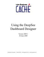
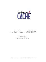
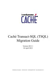
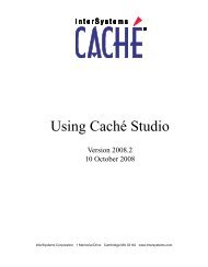
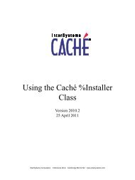
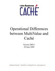
Introduction to <strong>Virtual</strong> <strong>Documents</strong>Persistent objects instantiate their entire contents as a formal set of properties, one property for each value in the messagedata. This is convenient in that any value in the persistent object is easy to access. When writing code, you simply referencea class property by name to get its value.Figure 1–1: <strong>Ensemble</strong> Message Object with a Standard Message Body1.3 <strong>Virtual</strong> <strong>Documents</strong> Compared to Standard MessagesNow consider the challenges of representing an EDI format as a classic <strong>Ensemble</strong> message: That is, a persistent object thatcontains an instantiated property to represent every field in every segment of the message.EDI document structure is simple enough when considered field by field, but any single document may be arbitrarily largeand complex, with hundreds of fields. Using the classic <strong>Ensemble</strong> message body would mean instantiating hundreds ofproperties to transmit a single document. This could be slow and unnecessary, given that many applications use only asmall number of the fields actually available in the document.To address these issues, <strong>Ensemble</strong> offers an alternative type of message body called a virtual document. A virtual documentallows you to send raw document content as the body of an <strong>Ensemble</strong> message, without constructing objects to hold thecontents of the document as a formal set of properties.The following diagram illustrates a virtual document. Like all <strong>Ensemble</strong> message objects, it consists of a message headerand message body, but the data items are not actually properties on the message body object. The message body containsonly one instantiated property, a document type. This property references a schema definition that tells <strong>Ensemble</strong> where tofind a specific data item, a virtual property, within the raw content.4 <strong>Ensemble</strong> <strong>Virtual</strong> <strong>Documents</strong>
Message Headers for <strong>Virtual</strong> <strong>Documents</strong>Figure 1–2: <strong>Ensemble</strong> Message Object with a <strong>Virtual</strong> Document Body1.4 Message Headers for <strong>Virtual</strong> <strong>Documents</strong>Because it has a standard message header, a virtual document behaves like any other <strong>Ensemble</strong> message. All the differentways of viewing, tracing, and managing messages using the Management Portal apply to a virtual document. There arespecial requirements for filtering and searching virtual properties; for details, see the chapter “Search Tables.”<strong>Ensemble</strong> <strong>Virtual</strong> <strong>Documents</strong> 5
2Schema DefinitionsThis chapter discusses schema definitions for EDI formats. It includes the following topics:• Overview of Schema Definitions• Schema Categories• DocTypes2.1 Overview of Schema DefinitionsAn <strong>Ensemble</strong> schema definition is a set of descriptions of the document structures allowed by a specific EDI standard. Assuch, a schema definition is an <strong>Ensemble</strong> concept, not to be confused with other concepts such as a database schema orXML schema. Each schema definition provides <strong>Ensemble</strong> with a complete view of an EDI standard. There is one schemadefinition for HL7 Version 2, one for X12, one for ASTM, and so on.In practical terms, a schema definition may contain only a subset of the standard in question; this depends on how theschema definition was imported into <strong>Ensemble</strong>.The schema definition for HL7 Version 2 is virtually complete. Every version of the HL7 Version 2 standard (2.1, 2.2, 2.3,2.3.1, 2.4, 2.5, 2.5.1, and 2.6) is already imported into <strong>Ensemble</strong>. All you need to do to complete the HL7 Version 2 schemadefinition is to define any custom document structures that your interfaces need to be able to route and transform.On the other hand, for X12 you must usually import an SEF file for each document structure that your applications exchange.For HL7 Version 3, the conventions are entirely different, since it is an XML-based exchange format.When you work with a schema definition, you are primarily concerned with the two subdivisions that organize it:• A document structure is the description that tells <strong>Ensemble</strong> where to find a data item within the raw contents of an<strong>Ensemble</strong> virtual document. Each document structure describes one type of virtual document.• A schema category is a grouping convention that provides a middle layer. Each schema definition contains one ormore schema categories. Each schema category contains one or more document structures.2.2 Schema CategoriesConventions for organizing a schema definition into schema categories and document structures can vary according to thestandard. In the HL7 Version 2 schema definition, each schema category corresponds to a complete version of the HL7<strong>Ensemble</strong> <strong>Virtual</strong> <strong>Documents</strong> 7
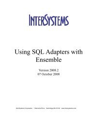
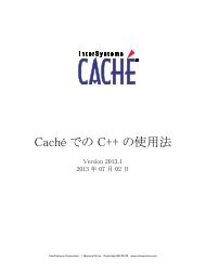
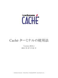
Schema DefinitionsVersion 2 standard (2.1, 2.2, 2.3, 2.3.1, 2.4, 2.5, 2.5.1, or 2.6) and each schema category may contain many different documentstructures. The following diagram shows a conceptual view of the schema definition for HL7 Version 2:For X12, the schema definition has a flatter organization, commonly with only one document structure per schema category:2.3 DocTypesTo properly identify a document structure within a schema definition, a virtual document’s DocType (document type)property must identify both subdivisions within the schema definition. The syntax for a DocType value is category:structurewhere:• category is the name of a schema category.• structure is the name of a document structure within the referenced categoryThe following figure represents a DocType value selecting the category and structure from a schema definition. In this casethe schema definition is for HL7 Version 2. This means that each schema category contains many document structures, asshown in the figure. However, even for a schema definition that contains one document structure per schema category, theDocType value must specify both category and structure.8 <strong>Ensemble</strong> <strong>Virtual</strong> <strong>Documents</strong>
DocTypesFigure 2–1: <strong>Virtual</strong> Document Showing Schema, Category, and Structure<strong>Ensemble</strong> <strong>Virtual</strong> <strong>Documents</strong> 9
3Segments and Fields<strong>Ensemble</strong> parses a message by applying its knowledge of the message’s segments and fields to the raw contents of themessage. The raw contents might look something like this. This example is an HL7 message that contains fictional dataand a combination of standard and custom segments. The right-hand portion of the text is truncated for reasons of space:MSH:;~\&:ST01C:A:HNS:A:20041209100007::ADT;A08:26070901:P:2.2:26070901::AL::::::PID:1::000616898;;;A;MR~00531098;;;;PI::LaRocca;Yan::19980202:F::4:924 Maple BlvPD1::::36904;Malynko;Brendan;(SACKETT);;;PAC;DOC:Press;Chris:::::::::NK1:1:Taylor;Chelsea:M;MOTHER:7702 Oak Street;;Reston;NV;93076;USA:854-495-4757:PV1:1:O:"":3:::36904;Tsatsulin;Patrick;(SACKETT);;;PAC;DOC:36904;Zampitello;EmmaPV2::::::::::::::::::::::N:::::::::::::::::::::::::::NAL1:"":"":"":"":"":""DG1:1:FF:"":UIT::A:::::::::0:DG1:2:I9:599.0:URIN TRACT INFECTION NOS::AM::::::::::DG1:3:I9:599.0:URIN TRACT INFECTION NOS::F:::::::::1:DG1:4:FF:"":UIT::W:::::::::1:DG1:5:FF::::F:""::::"";"";"";"";"";""::0.00:::GT1:1:00201148;;;;PI~00201148;;;;GN:Zimmerman;Mary::85 Ash Place;;Reston;NJ;5283IN1:1:130:400:BLUE CROSS:600 LAFAYETTE E;;DETROIT;MI;48226:BCBSM;"";""::004925:PIN2::378-58-6623:::I::::::::::::::::::::::::::::::::::::::::::::::::::::::::::::IN1:2:200:400:BLUE CROSS::""::004925:PCA::;PACKAGING CORP OF AM::::B:Jaynes;NataIN2::288-10-8224:::I::::::::::::::::::::::::::::::::::::::::::::::::::::::::::::IN1:3:109:410:BLUE CROSS OUT OF STATE::""::004925:PCA::;PACKAGING CORP OF AM::::IN2::520-14-9969:::L::::::::::::::::::::::::::::::::::::::::::::::::::::::::::::ACC:"":"":""::"":::""ZPI:1:N:::36904;Jenkins;George;(SACKETT);;;PAC;DOC:::::::3;NOT EMPLOYED::;3;MINOZPV:1:2;PERSONAL TRANSPORT::Y:HOM:::::::::::::::N::0:0:ZDG:5::200412080000ZIN:1:BC PPO:Y:::::121:ZIN:2:BC 1500:N::::::ZIN:3:BC PPO OUT OF STATE:Y:::::121:ZAB::::::::200412080000:::::The general principle behind EDI formats is that raw data stream is divided into lines or segments. These segments maybe further subdivided into fields and sub-fields. Separator characters mark the boundaries of segments, fields, and subfieldsin the stream. A terminator character (often a carriage return) marks the end of the segment.Figure 3–1: Segment Showing Fields and Separators<strong>Ensemble</strong> <strong>Virtual</strong> <strong>Documents</strong> 11
Segments and FieldsGenerally, an EDI standard defines a large number of possible segment structures to use as building blocks. Then it definesdocument structures by listing which of these segments each document structure may contain. Different document structuresmay use the same segments, but combine them in different sequences or quantities.For example, all HL7 Version 2 document structures start with the MSH message header segment. Additionally, documentstructures that describe patients entering and leaving the hospital (ADT or Admit/Discharge/Transfer documents) typicallyinclude the EVN event type, PID patient identifier, PV1 patient visit, DB1 disability, PD1 patient demographic, OBXobservations, and DG1 diagnosis, as shown in the following table. Each ADT document structure differs from the othersby the addition, deletion, or change in sequence of one of these segments. All of the following examples are from the HL72.3 category.StructureADT_A01ADT_A02ADT_A03ADT_A06ADT_A09ADT_A12Contains these segmentsMSN, EVN, PID, PD1, NK1, PV1, PV2, DB1, OBX, AL1, DG1, DRG, PR1, ROL, GT1, IN1, IN2,IN3, ACC, UB1, UB2MSN, EVN, PID, PD1, PV1, PV2, DB1, OBXMSN, EVN, PID, PD1, PV1, PV2, DB1, DG1, DRG, PR1, ROL, OBXMSN, EVN, PID, PD1, MRG, NK1, PV1, PV2, DB1, DRG, PR1, ROL, GT1, IN1, IN2, IN3, ACC,UB1, UB2MSN, EVN, PID, PD1, PV1, PV2, DB1, OBX, DG1MSN, EVN, PID, PD1, PV1, PV2, DB1, OBX, DG1. ADT_A12 differs only slightly from ADT_A09.The DG1 diagnosis field can be repeated in ADT_A09, but it can appear only once in ADT_A12.12 <strong>Ensemble</strong> <strong>Virtual</strong> <strong>Documents</strong>
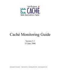
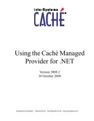
4<strong>Virtual</strong> PropertiesThis chapter discusses virtual properties. It includes the following topics:• <strong>Virtual</strong> Property Paths• Segments and Fields in a <strong>Virtual</strong> Property Path• Shortcuts When DocType Is UnimportantImportant:This chapter provides HL7 Version 2 examples, but the syntax for the virtual property path is the same foreach EDI format, except for XML virtual documents. (For XML virtual documents, an alternative syntaxis also available; see the <strong>Ensemble</strong> XML <strong>Virtual</strong> Document Development Guide.)4.1 <strong>Virtual</strong> Property PathsTo work with a virtual document, you must be able to identify a specific data item within it. The data item is called a virtualproperty. The syntax that <strong>Ensemble</strong> uses to specify the location of a virtual property is called a virtual property path.Conceptually, this path includes all of the units discussed in previous chapters:• category:structure — the DocType• segment:field — the path to a data value within a virtual document of that DocTypeThe following figure illustrates this convention.<strong>Ensemble</strong> <strong>Virtual</strong> <strong>Documents</strong> 13
<strong>Virtual</strong> PropertiesFigure 4–1: <strong>Virtual</strong> Property Identified by Category, Structure, Segment, and Field4.2 Segments and Fields in a <strong>Virtual</strong> Property PathGenerally the segment portion of the path identifies the target segment within a hierarchical document structure containinggroups and repeating blocks of segments. For example, an NTE segment in a 2.3:ORM_O01 message might be identifiedas:ORCgrp(1).OBRuniongrp.OBXgrp(3).NTE(1)Similarly, the field portion of the path identifies a target field within a hierarchical structure of fields, subfields, andrepeating groups within the target segment. As it happens, each field within NTE is simple, for example:SourceofCommentSo that the complete segment:field path looks like this:ORCgrp(1).OBRuniongrp.OBXgrp(3).NTE(1):SourceofCommentSome fields can have complex hierarchical structures. Suppose we look at a PID segment in the same 2.3:ORM_O01message structure. In the segment identified as:PIDgrp.PIDThere could be a field path as follows:14 <strong>Ensemble</strong> <strong>Virtual</strong> <strong>Documents</strong>
Shortcuts When DocType Is UnimportantPatientIDInternalID(1).identifiertypecodeUnlike segment paths, the field portion of the path generally allows numbers instead of names for fields and subfields; forexample, instead of the names previously shown, the following numbers may be used:3(1).5It is not necessary for you to memorize an entire EDI standard, such as HL7, to know which field names or numbers to usewhen working with virtual documents. The Management Portal provides pages to help you determine the correct segment:fieldpaths. (To access these pages, click <strong>Ensemble</strong>, and then click Interoperate.) The DTL editor also provides a view of thedocument structures used in a particular transformation.4.3 Shortcuts When DocType Is UnimportantOften when you need to identify a virtual property path, the specific DocType is clear from the context, so you only needto identify the segment:field path. There are also cases when a specific DocType is not important and any DocType fromthe schema definition that matches your search criteria is of interest. Consequently, there are two important shortcuts forvirtual property syntax used in BPL, DTL, and routing rules:• Curly brackets{segment:field}Curly bracket syntax is available in BPL, DTL, business rules (including routing rules), search filters, or search tables.The segment:field combination inside the curly brackets may use segment and field names, or numeric positions.However, names work only when the DocType (category:structure) is clearly identified within the current context.For example, a DTL data transformation always identifies the DocType of its source and target in its element.• Square brackets[segment:field]Square bracket syntax is available for business rules, search tables, and search filters only. The segment must be aname; field may be a name or number. Names can only be resolved when the DocType (category:structure) is knownat runtime. <strong>Ensemble</strong> can resolve a numeric field without knowing the specific message structure or schema. If thereis more than one result that matches the pattern in square brackets, this syntax returns a string that contains all matchingvalues, each value enclosed in angle brackets.The following shortcuts are available only when defining routing rules:• Round brackets or parentheses(multi-valued-property-path)• Angle bracketsFor details, see “<strong>Virtual</strong> Property Syntax” in the “Syntax Guide” appendix.<strong>Ensemble</strong> <strong>Virtual</strong> <strong>Documents</strong> 15
5Search TablesThis chapter discusses search tables for virtual documents. It includes the following topics:• Overview• Defining and Using a Search Table Class• Example Search Table Class• Search Table Superclass Variations for EDI Formats• Defining a Custom Search Table Class• Management of Search Tables• Customizing Queries Used by the Management Portal5.1 OverviewA search table is a specialized tool that enables <strong>Ensemble</strong> to index virtual properties as the basis for filter and searchoperations in the Message Viewer, Rules Editor, and other parts of the Management Portal.Previous chapters have explained that a virtual document is efficient because it contains a large amount of raw data but noinstantiated properties. Creating a search table enables <strong>Ensemble</strong> to efficiently index a few of the fields in a virtual documentso that these fields are available to be searched as if they were properties.5.2 Defining and Using a Search Table ClassTo define a search table class, use the following general procedure:• Create a subclass (or a copy, as you prefer) of the suitable class for your type of virtual document. See “Search TableSuperclasses for EDI Formats,” later in this chapter, which also provides links to books for specific EDI formats.• In this subclass, define virtual properties as needed. To do this, you define an XML document that identifies the virtualproperties that you want developers and administrators to be able to search efficiently.In the definition for a property, you use a property path as described in the previous chapter.Depending on the EDI format, some virtual properties might be predefined.<strong>Ensemble</strong> <strong>Virtual</strong> <strong>Documents</strong> 17
Search Tables• If this search table class is mapped to multiple namespaces, compile it in each of those namespaces, to ensure that themetadata local to each namespace is up to date.Important:Search table metadata is located in the default global database for each <strong>Ensemble</strong> namespace; therefore,changes to a search table class do not update metadata in all namespaces to which the class is mapped.When you compile this class, <strong>Ensemble</strong> generates code that dynamically fetches the local metadata for each search tableproperty and then caches the metadata if the process is running as an <strong>Ensemble</strong> host. If the property metadata is not present,as in the case where a mapped search table class does not have local metadata for a new property, the class still indexes allother properties and returns an error to indicate the metadata was not present. Similarly, when the message bodies aredeleted, <strong>Ensemble</strong> removes the corresponding entries from the search table; no work is required on your part.To use the search table class, specify it as a configuration option for the applicable business host. When that business hostprocesses messages, it uses the configured search table class to index those messages. For details, see the books listed inSee “Search Table Superclasses for EDI Formats,” later in this chapter.5.3 Example Search Table ClassThe following example shows a search table class. The SearchSpec XData block contains the elements thatdefine the search table.Class Demo.HL7.MsgRouter.SearchTable Extends EnsLib.HL7.SearchTable{XData SearchSpec [ XMLNamespace="http://www.intersystems.com/EnsSearchTable" ]{{1:4}_"|"_{1:3}{1:6}_"|"_{1:5}{1:7}[PID:5][IN1:4]{3:5}{ORCgrp().OBRuniongrp.OBRunion.OBR:UniversalServiceID.text}{PIDgrpgrp().ORCgrp(1).OBR:UniversalServiceID.text}}}The XMLNamespace declaration (as shown in the preceding example) enables Studio to provide word completion as youtype.5.4 Search Table Superclasses for EDI FormatsThe syntax shown in the previous example applies equally to HL7, X12, and so forth. The difference is that each EDI formatuses a different parent class for its search table definitions. These classes are as follows:18 <strong>Ensemble</strong> <strong>Virtual</strong> <strong>Documents</strong>
Defining Custom Search Table Classes• EnsLib.HL7.SearchTable for HL7 Version 2.For details, see “HL7 Search Tables” in the chapter “Elements of a Routing Production” of the <strong>Ensemble</strong> HL7 Version2 Development Guide.• EnsLib.EDI.X12.SearchTable for X12.For details, see “X12 Search Tables” in the chapter “Elements of a Routing Production” of the <strong>Ensemble</strong> X12Development Guide.• EnsLib.EDI.ASTM.SearchTable for ASTM E 1394–97.For details, see “ASTM Search Tables” in the chapter “Elements of a Routing Production” of the <strong>Ensemble</strong> ASTMDevelopment Guide.• EnsLib.EDI.EDIFACT.SearchTable for EDIFACT.For details, see “EDIFACT Search Tables” in the chapter “Message Handling and Syntax” of the <strong>Ensemble</strong> EDIFACTDevelopment Guide.• EnsLib.EDI.XML.SearchTable for XML virtual documents.For details, see “Defining Search Tables for XML <strong>Virtual</strong> <strong>Documents</strong>” in the <strong>Ensemble</strong> XML <strong>Virtual</strong> DocumentDevelopment Guide.5.5 Defining Custom Search Table ClassesIn some cases, the basic search table mechanism described in this chapter might not enable you to index messages as needed.In such cases, you can define and use custom search table classes.The class can define two kinds of properties. Within this topic, these properties are called: standard properties (which arestored in the search table) and virtual properties (which are not stored in the search table but instead are retrieved at runtime).Either kind of property is either indexed or not. If you index a property, more disk space is consumed but queries for thatproperty run more quickly. The Management Portal displays the indexed properties as a group above the non-indexed ones,so that users can select them appropriately.To define a custom search table class, define a class as follows:• Extend Ens.CustomSearchTable.This class defines one standard class property, DocId, which is indexed.• Define additional class properties as needed, and add indices for these class properties. For example:Property Type As %String(COLLATION = "EXACT");Index Type On Type [ Type = bitmap ];Note that collection properties are not currently directly supported by the query generation mechanisms. For a collectionproperty, use the Get<strong>Virtual</strong>PropertyList() method mechanism described below.• Optionally implement the GetPropertyList() method as needed.classmethod GetPropertyList(Output pIndexedProperties As %List, Output pProperties As %List) as%StatusWhere:– pIndexProperties is a $LISTBUILD list of standard properties that should be indexed.– pProperties is a $LISTBUILD list of standard properties to define.<strong>Ensemble</strong> <strong>Virtual</strong> <strong>Documents</strong> 19
Search TablesThe purpose of this step is to indicate which class properties are to be used as standard properties (see the definitionsbefore this list), as well as which of those should be indexed.By default, this method is generated, and <strong>Ensemble</strong> uses all class properties of the search table class as standard propertiesand indexes them all, except for private, internal, transient, and multidimensional properties.For virtual properties, implement Get<strong>Virtual</strong>PropertyList() instead (or in addition).• Optionally implement the Get<strong>Virtual</strong>PropertyList() method as needed.classmethod Get<strong>Virtual</strong>PropertyList(Output Get<strong>Virtual</strong>PropertyList As %List,Output p<strong>Virtual</strong>Properties As %List)as %StatusWhere:– Get<strong>Virtual</strong>PropertyList is a $LISTBUILD list of virtual properties that should be indexed.– p<strong>Virtual</strong>Properties is a $LISTBUILD list of the virtual properties to define.The purpose of this step is to indicate which class properties are to be used as virtual properties, as well as which ofthose should be indexed.For standard properties, implement GetPropertyList() instead (or in addition).• If you implement Get<strong>Virtual</strong>PropertyList(), also implement the Get<strong>Virtual</strong>Property() method. This method mustreturn the value of a virtual property, given a document ID and a virtual property name:classmethod Get<strong>Virtual</strong>Property(pDocID As %String,pPropName As %String,Output pPropValue As %String,ByRef pUserArgs) as %StatusWhere:– pDocID is the ID of a document in the custom search table.– pPropName is the name of a virtual property.– pPropValue is the value of that property.– pUserArgs specifies any arguments.• Implement the OnIndexDoc() method.ClassMethod OnIndexDoc(pDocObj As %Persistent, pSearchTable As Ens.CustomSearchTable) As %StatusThis method should specify how to populate a given row in the search table from properties in a supplied message.• Implement the %OnDelete() method and %OnDelete() triggers as follows:ClassMethod %OnDelete(oid As %ObjectIdentity) As %Status [ Private ]{Set tID = $$$oidPrimary(oid)Quit ##class(Ens.SearchTableBase).RemoveSearchTableEntries(..%ClassName(1),tID,1)}Trigger OnDelete [ Event = DELETE ]{Set %ok = ##class(Ens.SearchTableBase).RemoveSearchTableEntries(..%ClassName(1),{%%ID},1)Quit}This step ensures that <strong>Ensemble</strong> removes any search table entries related to a particular message when the messagebody is deleted via object access or SQL access.For OnProcessCondition() and additional options, see the class reference for Ens.CustomSearchTable.20 <strong>Ensemble</strong> <strong>Virtual</strong> <strong>Documents</strong>
Management of Search TablesFor an example, see Demo.CustomSearchTable.Sample.5.6 Management of Search TablesThe class Ens.DocClassMap manages all the search tables (including custom search tables). It writes to and reads from aglobal (^Ens.DocClassMap). This global indicates, for each message class, which search tables contain data for it. Notethat you should never edit this global directly.The <strong>Ensemble</strong> classes use this class to remove search table entries when message bodies are deleted.It should not normally be necessary to use this class directly. However, if the data in ^Ens.DocClassMap is lost or damaged,use the RebuildMap() method of this class to recreate the global. For details, see the class reference for Ens.DocClassMap.5.7 Customizing Queries Used by the Management PortalWhen users search for messages in the Message Viewer and the Message Bank Message Viewer pages in the ManagementPortal, <strong>Ensemble</strong> generates and then uses queries. In advanced cases, you can customize how <strong>Ensemble</strong> generates thesequeries. To do so, use the following general procedure:• Define a subclass of EnsPortal.MsgFilter.AbstractAssistant. For details, see the class reference for that class.• Set the name of the class into ^EnsPortal.Settings("MessageViewer","AssistantClass") for the Message Viewer or^EnsPortal.Settings("MsgBankViewer","AssistantClass") for the Message Bank Viewer.<strong>Ensemble</strong> <strong>Virtual</strong> <strong>Documents</strong> 21
ASyntax GuideThis appendix describes the syntax details that support the virtual property model. The information in this chapter appliesequally to HL7 Version 2, X12, and so forth. Topics include:• <strong>Virtual</strong> Property Syntax• Literal String Syntax• Schema Category SyntaxA.1 <strong>Virtual</strong> Property SyntaxThis section explains the correct syntax to use when referring to virtual properties from statements in BPL, DTL, ObjectScript,Caché Basic, business rules (including routing rules), search filters, or search tables. These syntax conventions provide theequivalent of various method calls that are either not possible in certain contexts (business rules) or that are so frequentlyused that a shortcut is helpful. The shortcuts are as follows.• Curly brackets{segment:field}This is equivalent to using the GetValueAt() method.• Square brackets[segment:field]• Round brackets or parentheses(multi-valued-property-path)• Angle brackets<strong>Ensemble</strong> <strong>Virtual</strong> <strong>Documents</strong> 23
Syntax GuideTable I–1: Supported Syntaxes for <strong>Virtual</strong> Property Paths, by ContextSyntaxBPL and DTL (exceptfor and elements) elements ofBPL and DTLbusiness rulessearch filters andsearch tablesGetValueAt()supportedsupportednot supportednot supported{} Syntaxsupportednot supportedsupportedsupported[] Syntaxnot supportednot supportedsupportedsupported() Syntaxnot supportednot supportedsupportednot supported Syntaxnot supportednot supportedsupportednot supportedA.1.1 Curly Bracket { } SyntaxBusiness rules, search tables, search filters, and certain BPL and DTL elements support the curly bracket {} shortcut inplace of calling a message method such as GetValueAt() to access the value of a virtual property. The syntax is as follows:myHL7Message.{my<strong>Virtual</strong>PropertyPath}This is equivalent to the following method call, which returns the value of the specified virtual property. The specificmessage structure or document type must be known.msg.GetValueAt("segment:field")Note:The BPL and DTL elements and elements do not support curly bracket syntax.The segment:field string must be a valid virtual property path. Here is a BPL example:Or consider this DTL example:Here is an excerpt from a search table:{1:10}Curly bracket {} syntax is simpler than a method call, so you generally use {} instead of calling GetValueAt(). However,curly brackets are not supported within or statements in BPL or DTL. Here you must use the appropriatemethod call (GetValueAt() or SetValueAt()) to work with virtual properties.For curly bracket syntax to resolve, the message structure must be known. If the message structure is unknown in the currentcontext, you may use square bracket [ ] syntax to match the segment and field regardless of message structure.A.1.1.1 <strong>Virtual</strong> Property PathA virtual property path is a name in two parts, separated by a colon:24 <strong>Ensemble</strong> <strong>Virtual</strong> <strong>Documents</strong>
<strong>Virtual</strong> Property Syntaxsegment:fieldWhere:• segment identifies a message segment.• field identifies a field within that message segment.• A colon : separates segment and field.• A dot . separates hierarchical levels within segment or field.• Parentheses containing a number (n) provide an index into an array of repeating elements.For example:NK1(2):Address.streetaddressPR1grp(1).AUTgrp.CTD:ContactAddress.streetaddressNote:A virtual property path is relative to a specific message structure, and might not be valid in any other messagestructure. The Management Portal provides pages to help you determine paths. (To access these pages, click<strong>Ensemble</strong>, and then click Interoperate.)You can use numeric or symbolic names in the segment address or field address portion of the virtual property path. Followingare two sample statements such as might appear within a DTL data transformation:The target has a DG1 segment with a field number 16.2 named DiagnosingClinician.familylastname. That means the two statements in the above example are equivalent.You cannot mix numbers and names on the same side of the colon. For example {DG1(1):DiagnosingClinician(1).familylastname}is allowed but {DG1(1):16(1).familylastname} is not allowed. On the left side of the colon (in the segment portion)numerics are of limited use because the numeric index of a particular segment is usually not known. MSH is an exceptionbecause it is always the first segment.All of the following DTL statements are equivalent, and equally valid, because MSH is segment 1 and ReceivingApplicationis field 5 of MSH:A.1.1.2 Counting FieldsIn any context where you can use curly brackets {}, if the final field is a repeating field, you can use (*) at the end of anexpression to return the number of fields. For example, ORCgroup is a repeating field in an HL7 message. The followingexpression returns the number of ORC groups in the first PID group:HL7.{PIDgrpgrp(1).ORCgrp(*)}You can also use this within GetValueAt().A.1.1.3 Repeating Field ( ) SyntaxWhen you are using curly bracket {} notation in BPL or DTL, the shortcut () iterates through every instance of a repeatingfield within an HL7 message structure. For example, the following single line of DTL:<strong>Ensemble</strong> <strong>Virtual</strong> <strong>Documents</strong> 25
Syntax GuideIs equivalent to the following three lines of equally valid DTL:The same () convention is also available in BPL.A.1.1.4 Wholesale CopyWhen you are using curly bracket {} notation in BPL or DTL, you can copy whole segments, groups of segments, or wholecomposite fields within a segment. Thus, the following DTL statements are all legal:The last line of the previous example uses the caret (^) as a component separator character. For details specific to each EDIformat, see:• “HL7 Separator Characters” in the <strong>Ensemble</strong> HL7 Version 2 Development Guide• “ASTM Separator Characters” in the <strong>Ensemble</strong> ASTM Development GuideTo create a target object that is an exact copy of the source, do not use:Instead use the create='copy' attribute in the containing element, as in the following example:The create option may have one of the following values:• new — Create a new object of the target type, before executing the elements within the data transformation. This isthe default.• copy — Create a copy of the source object to use as the target object, before executing the elements within the transform.• existing — Use an existing object, provided by the caller of the data transformation, as the target object.A.1.2 Square Bracket [ ] SyntaxSquare bracket [] syntax is available for business rules, search tables, and search filters only. The syntax is as follows:[segment:field]This finds values in named segments regardless of message structure. If there is more than one instance of the segment typein the message, this syntax returns a string that contains all matching values, each value enclosed in angle brackets. Thesegment:field combination inside the square brackets follows the same rules as the virtual property path for curly brackets{ } except that the field must be in numeric format.When you use square brackets, <strong>Ensemble</strong> can resolve the numeric path without knowing the specific message structure orschema. This is different from curly brackets {} which require you to identify the message structure. For example, a DTLdata transformation identifies the message structure of the source and the target messages with attributes of the element (sourceDocType and targetDocType) so that you can use curly bracket syntax.Square bracket syntax supports the repeating field shortcut () only in the field portion of the property path (segment:field).There is no way to specify that a segment might repeat; in fact this is not necessary. If multiple segments of the same type26 <strong>Ensemble</strong> <strong>Virtual</strong> <strong>Documents</strong>
<strong>Virtual</strong> Property Syntaxexist in the message, square bracket syntax matches all segments of that type in the message. Square bracket syntax returnsa string that encloses each value in angle brackets.The following excerpt from a search table class shows two valid ways to match all the FT1 segments found in a messagethat contains several FT1 segments:[FT1:12.1][FT1:6]In each case if the syntax returns multiple values a, b, and c, they appear in a single string like this:The syntax does not equate with the default behavior of FindSegmentValues(). Instead, it modifies the separator and enclosesthe result in angle brackets, so the square bracket syntax equates to the following method call:""A.1.3 Parenthesis () Syntax in Business RulesParenthesis () or round bracket syntax is available for business rules only. A pair of parentheses can be used as bracketsin an HL7 routing rule as follows:HL7.(multi-valued-property-path)This equates to:msg.GetValues("multi-valued-property-path")A multi-valued property path is one that uses the repeating field shortcut () to iterate through every instance of a repeatingfield within an HL7 message structure. You can use this in combination with round bracket syntax to return all values fromall repetitions of a field. If the syntax returns multiple values a, b, and c, they appear in a single string enclosed in anglebrackets, like this:For example, in an HL7 routing rule, the syntax HL7.(NK1():1) finds the values of the first field in all of the multipleNK1 segments in the HL7 message object represented by the special variable HL7.A.1.4 Angle Bracket Syntax in Business RulesAngle bracket syntax is available for business rules only. An XPath expression in angle brackets such as the following:Equates to:GetXPathValues(msg.stream,"context|expression")GetXPathValues() is a convenience method in the rules engine. It operates on a message that contains a stream propertywhose contents are an XML document. The method applies an XPath expression to the XML document within the streamproperty, and returns all matching values. If the context| part of the XPath argument is missing, <strong>Ensemble</strong> searches theentire XML document. If the syntax returns multiple values a, b, and c they appear in a single string enclosed in anglebrackets, like this:The following is an example of angle bracket syntax in an HL7 routing rule: the syntax HL7. results in amatch if the XML document in the message stream property contains the word fracture.<strong>Ensemble</strong> <strong>Virtual</strong> <strong>Documents</strong> 27
Syntax GuideA.2 Literal String SyntaxOften a DTL data transformation copies existing message data from fields within a source message to fields within a targetmessage. The following DTL statement shows an example of this for an HL7 Version 2 message routing production:In cases like this <strong>Ensemble</strong> preserves all of the special characters within the HL7 message data, such as separator charactersand escape sequences, and handles them automatically, even if the specific conventions regarding these characters are differenton the source (incoming) and target (outgoing) sides. The business services and business operations that handle theincoming and outgoing sides of HL7 message transmission handle all of these issues elegantly without needing anyadjustments to occur within the data transformation.However, sometimes a DTL data transformation needs to assign a literal string value to a field, as in the following DTLstatement:Important:In BPL and DTL, a literal string value must provide its own enclosing quotes, distinct from those thatenclose the entire value, and of a different type. Thus, in the example above, value='"ULTRA"' insertsthe string ULTRA into the ReceivingApplication field of the target message. value='ULTRA' orvalue="ULTRA" are not effective.When a DTL data transformation assigns a literal string value to a target message field, it is providing HL7 message datadirectly, rather than copying it from the source message. In constructing a DTL statement like this, you need to be awareof the HL7 separators and escape sequences that apply in the source (incoming) message, so that your literal string matchesthese conventions correctly.It does not matter which HL7 separators and escape sequences apply on the target (outgoing) side; they may be different.What matters within the data transformation is that any literal strings you create must match the HL7 separators and escapesequences of the source message. Then, after the data transformation constructs the target message object, the HL7 businessoperation automatically adjusts the HL7 separators and escape sequences to those expected by the target.You should also be aware that, because BPL and DTL are extensions of XML, whenever you construct a literal string fora BPL or DTL statement there are certain characters you can only represent using XML entities. A limited number ofnumeric character codes are also supported in constructing BPL or DTL strings. The next several topics explain therequirements for various types of special character.Finally, remember that the value attribute in a DTL statement can be a simple string, as in most of the examplesin this book:value='"string"'Or the DTL value can be a complex string expression using the scripting language specified by the containing element. This language can be either Caché Basic or ObjectScript; if not specified it is ObjectScript. The same is true fora BPL statement, which uses the scripting language specified by the containing element; otherwise ituses ObjectScript.When constructing complex literal strings, keep in mind:• In ObjectScript, the concatenation operator is the _ (underscore) character, as in:value='"prefix"_source.{MSH:ReceivingApplication}_"suffix"'In Basic, the concatenation operator is & (ampersand).• To learn about useful ObjectScript string functions, such as $CHAR and $PIECE, see the Caché ObjectScript Reference.For Basic equivalents, see the Caché Basic Reference.28 <strong>Ensemble</strong> <strong>Virtual</strong> <strong>Documents</strong>
Literal String Syntax• For a general introduction, see Using Caché ObjectScript or Using Caché Basic.A.2.1 XML EntitiesWhen you a literal string value to a property using BPL or DTL, you must substitute XML entities for certaincharacters. This has nothing to do with HL7 or any other EDI format. The restriction exists because BPL and DTL areextensions of XML. Within all BPL or DTL statements (aside from the contents of or statements) certaincharacters must be represented by XML entities. The following table lists them.Table I–2: XML Entities for Use in BPL and DTL StringsCharacter>,
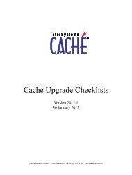
Syntax Guide• <strong>Ensemble</strong> ASTM Development Guide– ASTM Separator Characters– ASTM Escape Sequences• <strong>Ensemble</strong> EDIFACT Development Guide– EDIFACT Separator CharactersA.2.2 Numeric Character CodesDecimal or hexadecimal representations of characters are permitted within literal strings in BPL and DTL.The string &#n; represents a Unicode character when n is a decimal Unicode character number. One example is éfor the Latin e character with acute accent mark (é).Alternatively, the string &#xh; represents a Unicode character when h is a hexadecimal Unicode character number. Oneexample is ¿ for the inverted question mark (¿).Important:Due to the limitations of single-byte encoding format for HL7, the numeric value in character codes inliteral strings placed in HL7 messages can be no higher than the decimal value 255 or hexadecimal x00FF.A.3 Schema Category SyntaxA schema category definition can be viewed in XML format by opening its *.HL7 file in Studio. Each *.HL7 file is an XMLdocument whose top-level container is the element. Statements within the element define HL7message structures.When viewed in Studio, an *.HL7 file resembles the following figure. The actual text is longer and wider than the example,which contains ellipses (...) for omitted items and is truncated at right. This example is the schema category definition forHL7 Version 2.5.30 <strong>Ensemble</strong> <strong>Virtual</strong> <strong>Documents</strong>
Schema Category SyntaxFigure I–1: Studio View of a Built-in HL7 Category DefinitionInside the element, the example begins with two sets of XML elements that you do not need to work with: and . These elements group HL7 messages into functional categories. The exampleends with two other XML elements that you do not need to work with: and . These elementsdefine the range of possible values for certain fields in certain messages.When you create a custom schema category, you supplement an existing schema by defining custom segments (Z-segments)and then stating which message types and message structures may contain those segments. To accomplish this, you onlyneed to work with the XML elements , , and .Important:Never edit the built-in schema category definition files. When you need to use custom message types thatcontain Z-segments, create a custom schema category definition that uses a built-in schema category definitionas its schema base.A custom schema category definition is simpler than a built-in definition and contains fewer statements. Everything in thebase category is included in the custom schema category definition. There is no need to repeat the definitions of standardmessage types. You only need to define custom message types. The conventions for doing this are as follows:<strong>Ensemble</strong> <strong>Virtual</strong> <strong>Documents</strong> 31
Syntax GuideWhat to DefineCustom schema category definitionCustom segments (Z-segments)Any message structures that include custom segmentsAny message types that include message structures with custom segments. Amessage type identifies:How to Define It• The message structure to send• The message structure to expect in responseWhen viewed in Studio, a custom schema category definition resembles the following figure. The actual text is wider thanthe example, which is truncated at right. You can view the complete example by opening the schema definition fileDemo.HL7.MsgRouter.Schema.HL7 in the ENSDEMO namespace.Figure I–2: Studio View of a Custom HL7 Category DefinitionA.3.1 The element is the top-level container for the XML document that describes the custom schema category. Thefollowing is an example of syntax for a custom schema category definition:The following table describes the attributes.Table I–3: Attributes for the Element in Schema Category DefinitionsAttributenameDescriptionName displayed in the Schema Structures pagein the list of available schema categories.ValueString. For convenience, use the name of the.HL7 file.32 <strong>Ensemble</strong> <strong>Virtual</strong> <strong>Documents</strong>
Schema Category SyntaxAttributestdbaseDescriptionWhen 1 (true), this block describesa standard HL7 schema category. The defaultis 0 (false).Identifies the schema category that is the basefor this custom schema category. Everydefinition in the schema base is automaticallyincluded in the custom category; statements inthe custom schema category simply add to thebase.ValueFor standard schema category definitions only.Do not use std in a custom schema.The name of a standard or custom schemacategory defined using a block inanother .HL7 file.A.3.2 A element may contain one or more elements. Each element definesthe structure of a custom segment (Z-segment). The following is an example of element syntax:The following table describes the attributes.Table I–4: Attributes for the Element in Schema Category DefinitionsAttributenamedescriptionDescriptionName displayed in the Schema Structures pagein the list of available segment structures.Text description of the segment contents,displayed in the Schema Structures page andas a tooltip for the Document Viewer page.Value3–character string. By convention, customsegment names begin with the letter Z.StringA.3.3 A element may contain one or more elements. Each element describes one field of the custom segment, in sequential order from top to bottom. The following is an example of element syntax:The following table describes the attributes.<strong>Ensemble</strong> <strong>Virtual</strong> <strong>Documents</strong> 33
Syntax GuideTable I–5: Attributes for the Element in Schema Category DefinitionsAttributepiececodetabledatastructdescriptionsymbolDescriptionNumber displayed in the Schema Structurespage when the user asks to view details ofthe segment that contains this field. Thisnumber can be used to identify the field in avirtual property path.Code table that enumerates a list of validvalues for this field. This attribute is typicallynot used in a custom schema.Data structure that specifies how to interpretthe values in this field. This attribute istypically not used in a custom schema.Text description of the field contents,displayed in the Schema Structures page andas a tooltip for the Document Viewer page.Symbol that indicates the requirements forpresence, absence, or repetition of this fieldwithin the segment.This field is optional. It serves as an indicatoron the Schema Structures page. It does notactually control the requirement or repetitionof fields. See required and ifrepeating.ValueInteger. Each withina must use piece valuesin sequential order, beginning at 1 andincrementing by 1.The name of a code table defined using a block.The name of a data structure defined using a block.StringA single character:• ! means 1 only. The field must appear, butonly once.• ? means 0 or 1. The field may appear, butat most once.• + means 1 or more. The field may repeatone or more times.• * means 0 or more. The field may repeatzero or more times.• & means the field may be present, andmay repeat, but only under certain conditions.lengthrequiredUpper limit on the number of characters thatcan be present in this field.Whether or not this field must be present inthe segment.IntegerA single character:• C means conditional• O means optional• R means requiredifrepeatingWhether or not this field may repeat withinthe segment.Integer. 0 means no, 1 means yes.34 <strong>Ensemble</strong> <strong>Virtual</strong> <strong>Documents</strong>
Schema Category SyntaxA.3.4 A element may contain one or more elements. Each element providesa specification for the number and arrangements of segments in a message structure. The following is an example of element syntax:The following table describes the attributes.Table I–6: Attributes for the Element in Schema Category DefinitionsAttributenamedefinitiondescriptionDescriptionName displayed in the Schema Structurespage in the list of available messagestructures.Specification for the number andarrangements of segments in the messagestructure. May include a mix of standard andcustom message segments. See syntax rulesbelow.Text description of the field contents,displayed in the Schema Structures page andas a tooltip for the Document Viewer page.Value3–character string, plus an underscore (_),plus a 3–character string.String that includes the 3–character namevalues for standard or custom messagesegments defined using StringSyntax for the definition string works as follows:• Keep the entire string all on one line• List each segment sequentially from left to right• When listing a segment, use its name value as defined by a • Separate a segment from the next segment by a ~ (tilde) character• If a segment or block of segments repeats, enclose the repeating part in {~ and ~}• If a segment or block of segments is optional, enclose the optional part in [~ and ~]Within a definition, a name may be simple, in which case <strong>Ensemble</strong> assumes the value refers to a custom block within the same .HL7 file. Alternatively, a name may refer to a standard message structure from the schema base.This means it is defined in the .HL7 file identified by the base attribute in the containing element. To indicatethis, the name must use the prefix:base:So that <strong>Ensemble</strong> can find the appropriate in the other file. No other external .HL7 file can be referenced;only the schema base.In the example at the beginning of this topic, only the ZSI segment is defined in the same .HL7 file.The other segments (MSH, MFI, MFE, OM1, and Hxx) are all defined in the schema base.<strong>Ensemble</strong> <strong>Virtual</strong> <strong>Documents</strong> 35
Syntax GuideA.3.5 A element may contain one or more elements. entries define any messagetypes that include message structures that have custom segments. A element is a simple list of two items:• A message structure to send• A message structure to expect in responseThe following is an example of element syntax:The following table describes the attributes.Table I–7: Attributes for the Element in Schema Category DefinitionsAttributenamestructurereturntypeDescriptionName displayed in the Schema Structurespage in the list of available message types.The message structure to send.The message structure to expect in response.This must be a valid ACK message structure.Make sure the returntype has a value fromthe schema base. For example:returntype="base:ACK"Value3–character string, plus an underscore (_), plusa 3–character string.The name of a standard or custom messagestructure defined using The name of a standard or custom messagestructure defined using structure values can be simple name values from the current .HL7 file. If a file contains syntax like the following, wherethe structure is MFN_M03:Then the same file must also contain syntax like the following, to define MFN_M03:Alternatively, structure or returntype values can refer to a standard message structures from the schema base. To indicatethis, the values must use the prefix:base:So that <strong>Ensemble</strong> can find the appropriate entries, in the .HL7 file identified by the base attribute inthe containing element. No other external .HL7 file can be referenced; only the schema base.The following example uses both styles of syntax. This example defines a custom message type MFN_M03 that sends acustom MFN_M03 and receives a standard MFK_M03 as a response.36 <strong>Ensemble</strong> <strong>Virtual</strong> <strong>Documents</strong>