08360-1 SECTION 08360 OVERHEAD DOORS PART 1 ... - Clopay
08360-1 SECTION 08360 OVERHEAD DOORS PART 1 ... - Clopay
08360-1 SECTION 08360 OVERHEAD DOORS PART 1 ... - Clopay

Create successful ePaper yourself
Turn your PDF publications into a flip-book with our unique Google optimized e-Paper software.
<strong>SECTION</strong> <strong>08360</strong><strong>OVERHEAD</strong> <strong>DOORS</strong><strong>PART</strong> 1 GENERAL1.1 <strong>SECTION</strong> INCLUDESA. Sectional overhead doors of the following types:1. Light ribbed steel doors, thermally-broken, polyurethane insulated. (Model3717)2. Electric door operators1.2 RELATED <strong>SECTION</strong>SA. Section 05500 - Metal Fabrications: Steel channel opening frame.B. Section 06100 - Rough Carpentry: Rough wood framing and blocking for dooropening.C. Section 08710 - Door Hardware: Lock cylinders.D. Section 11150 - Parking Control Equipment: Remote door control.E. Division 16 Sections: Electrical service and connections for powered operators.1.3 REFERENCESA. ASTM A 653/A 653M - Specification for Steel Sheet, Zinc-Coated (Galvanized) orZinc-Iron Alloy-Coated (Galvannealed) by the Hot-Dip Process.B. ASTM A 924/A 924M - Specification for General Requirements for Steel Sheet,Metallic-Coated by the Hot-Dip Process.C. ASTM B 209/209M - Specification for Aluminum and Aluminum-Alloy Sheet andPlate.D. ASTM B 221/221M - Specification for Aluminum and Aluminum-Alloy Extruded Bars,Rods, Wire, Profiles, and Tubes.1.4 SUBMITTALSA. Submit under provisions of Section 01300.B. [ Product Data ]: Manufacturer's data sheets on each product to be used, including:1. Preparation instructions and recommendations.2. Storage and handling requirements and recommendations.3. Installation methods.4. Operation and maintenance data.5. Nameplate data and ratings for motors.<strong>08360</strong>-1
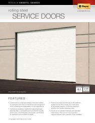
C. Shop Drawings: Include opening dimensions and required tolerances, connectiondetails, anchorage spacing, hardware locations, and installation details.D. Selection Samples: For each finish specified, two complete sets of color chipsrepresenting manufacturer's full range of available colors and patterns.E. Verification Samples: For each finish specified, two samples, minimum size 6inches (150 mm) square, representing actual product, color, and patterns.1.5 WIND PERFORMANCE REQUIREMENTSA. Design doors to withstand positive and negative wind loads as calculated inaccordance with applicable building code.1. Design Wind Load: ________lb/sf (_____kPa).2. Safety Factor: 1.5 times design wind load.1.6 QUALITY ASSURANCEA. Manufacturer Qualifications: Company specializing in manufacturing the types ofdoors specified in this section, with not less than ten years of documentedexperience.B. Installer Qualifications: Company specializing in installing the types of productsspecified in this section, with minimum of five years of documented experience, andapproved by the door manufacturer.1.7 WARRANTYA. Finish Warranty: Provide manufacturer's standard finish warranty against rustthrough.1. Warranty period: 10 years.B. Delamination Warranty: Provide manufacturer's standard warranty againstdelamination.1. Warranty period: 10 years.<strong>PART</strong> 2 PRODUCTS2.1 MANUFACTURERSA. Acceptable Manufacturer: <strong>Clopay</strong> Building Products Company, which is located at:8585 Duke Blvd. ASD; Mason, OH 45040-3101; Toll Free Tel: 800-526-4301prompt #3; Fax: 888-434-3193; Email: CIA@clopay.com Web:www.clopaycommercial.comB. Substitutions: Not permitted.C. Requests for substitutions will be considered in accordance with provisions ofSection 01600.2.2 LIGHT RIBBED STEEL <strong>DOORS</strong>, THERMALLY-BROKEN, POLYURETHANE INSULATEDA. Door Construction:1. Panels: Foamed in place Polyurethane core construction between exteriorand interior steel skins.2. Steel Skins: Formed from roll formed commercial or drawing quality steelsheet, hot-dip galvanized per ASTM A 924/A 924M and ASTM A 653/A 653M,pre-painted with primer and baked-on polyester topcoat; sections formed to<strong>08360</strong>-2
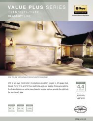
create weather tight tongue-in-groove meeting joint.3. Reinforcing: Galvanized and primed steel reinforcement located under eachhinge location, pre-punched for hinge attachment.4. Handle: High impact polymer step plate/lift handle on bottom panel section.B. Heavy Duty 1-3/4-inches (45 mm) Door: <strong>Clopay</strong> Model 3717.1. Maximum Door Size: 32 ft, 2 inches (9.8 m) wide by 26 ft (7.9 m) high.2. Overall Panel Thickness: 1-3/4-inches (45 mm).3. Steel Skin Thickness: Minimum 27 gauge 0.016 inch (0.40 mm) exterior;minimum 28 gauge 0.015 inch (0.38 mm) interior.4. End Stiles: Galvanized steel end stiles, engineered for easy hardwareattachment through pre-punched holes. Minimum 18 gauge, 0.045 inch (1.14mm) thick for single end hinge style and 16 gauge .056 inch (1.42 mm)minimum for double end hinge style.5. Astragal: U-shaped flexible PVC in retainer of full-length 0.055 inch (1.4 mm)rigid PVC.6. Thermal Resistance (R-value): 16.2 deg F hr sq ft/Btu (2.7 (K sq m)/W);calculated door section R-value in accordance with DASMA TDS-163.7. Windows: None.8. Windows: Extruded polypropylene windows measuring 8 inches by 24 inches(200 mm by 600 mm).a. Glazing: 7/8 inch (22 mm) insulated glass.b. Glazing: 7/8 inch (22 mm) insulated tempered glass.c. Glazing: 1/4 inch (6 mm) tempered glass.9. Windows: Extruded polypropylene windows measuring 12 inches by 24inches (305 mm by 600 mm).a. Glazing: 7/8 inch (22 mm) insulated glass.b. Glazing: 7/8 inch (22 mm) insulated tempered glass.c. Glazing: 1/4 inch (6 mm) tempered glass.10. Windows: Black extruded polypropylene windows with rounded cornersmeasuring 13 inches by 26 inches (303 mm by 606 mm).a. Glazing: 5/8 inch (16 mm) double pane acrylic.b. Glazing: 5/8 inch (16 mm) double pane lexan.11. Windows: Full vision aluminum section, pre-painted to match door finish.a. Glazing: 1/8 inch (3 mm) DSB sheet glass.b. Glazing: 1/8 inch (3 mm) tempered sheet glass.c. Glazing: 1/8 inch (3 mm) clear acrylic glazing.d. Glazing: 1/8 inch (3 mm) clear polycarbonate sheet.e. Glazing: 1/4 in. (6mm) ribbed double-wall polycarbonate glazing.f. Glazing: 1/2 inch (12 mm) insulated glass.g. Glazing: 1/2 inch (12 mm) insulated tempered glass.12. Finish: Interior stucco embossed texture with shallow U ribbed pattern, whitecolor. Exterior stucco embossed with light ribbed pattern, exterior color asfollows:a. White.b. Brown.c. Tan.d. Grey.e. Trinar White.f. Trinar Beige.13. Locking: No Lock.14. Locking: Inside spring loaded slide bolt lock on end stile that engages slot intrack.a. Provide one inside slide lock.b. Provide two inside slide lock.<strong>08360</strong>-3
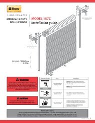
c. Provide five pin cylinder lock with outside key.15. Weatherstripping: Provide complete perimeter seals. Provide flexible top seal,flexible jamb seal and U shaped bottom seal.16. Tracks: Vertical tracks minimum 0.061 inch (1.55 mm) galvanized steeltapered and mounted for wedge type closing. Horizontal tracks minimum0.075 inch (1.91 mm) galvanized steel, reinforced with minimum 0.0897 inch(2.28 mm) galvanized steel angles as required:a. Track Width: 2 inches (50 mm).b. Track Width: 3 inches (75 mm).c. Provide standard lift tracks with 15 inches (381 mm) radius track asindicated.d. Provide vertical lift tracks as indicated.e. Provide high lift tracks as indicated.f. Provide tracks that follow roof slope tracks as indicated.g. Provide low headroom tracks as indicated.17. Spring Counterbalance: Torsion spring counterbalance mechanism sized toweight of the door, with a helically wound, oil tempered torsion springmounted on a steel shaft; cable drum of die cast aluminum with high strengthgalvanized aircraft cable with minimum 7 to 1 safety factor.a. Standard Cycle Spring: 10,000 cycle.b. High Cycle Spring: 25,000 cycles.c. High Cycle Spring: 50,000 cycles.d. High Cycle Spring: 100,000 cycles.18. Break-Away Bottom Section: Integral part of door; with fiberglass or 1/8 inch(3 mm) polycarbonate lined bottom section with flexible neoprene rubber sideedges; exterior to match door face.a. Single breakaway bottom section for doors up to 20 feet (6 m) wide.b. Double breakaway botton section for doors up to 14 feet (4.3 m) wide.2.3 ELECTRIC DOOR OPERATORSA. General: Provide electric door operator provided by door manufacturer for doorwith operational life specified complete with electric motor and factory pre-wiredmotor controls, starter, gear-reduction unit, clutch, remote-control stations, controldevices, integral gearing for locking door, and accessories required for properoperation. Comply with NFPA 70.1. Solenoid-operated brake.B. Disconnect Device: Provide hand-operated disconnect or mechanism foremergency manual operation while disconnecting motor, without affecting timing oflimit switch. Mount disconnect and operator so they are accessible from floor level.Include interlock device to automatically prevent motor from operating whenemergency operator is engaged.C. Design operator so motor may be removed without disturbing limit switch adjustmentand without affecting emergency auxiliary operator.D. Provide control equipment complying with NEMA ICS1, NEMA ICS 2, and NEMAICS 6, with NFPA 70 Class 2 control circuit, maximum 24-V, AC or DC.E. Electric Motors: Provide high-starting torque, reversible, continuous-duty, Class Ainsulated, electric motor, complying with NEMA MG 1, with overload protection,sized to start, accelerate, and operate door in either direction, from any position, atnot less than 2/3 fps (0.2 m/s) and not more than 1 fps (.03m/s), without exceedingnameplate ratings or considering service factor.1. Type: Mechanical.<strong>08360</strong>-4
2. Type: Solid State.3. Type: Jackshaft.4. Type: Trolley.5. HP:a. 1/3 hp (246 W).b. 1/2 hp (373 W).c. 3/4hp (559 W).d. 1 hp (746 W).6. Power Characteristics:a. 115 V.b. 220 V.c. 460 V.d. 1 phase.e. 3 phase.7. Service Factor:a. NEMA MG 1.b. NEMA 4 watertight.c. NEMA 9 waterproof.d. NEMA 10 oil resistant.e. NEMA 12 explosion resistant.8. Coordinate wiring requirements and electrical characteristics of motors withbuilding electrical system.F. Remote Control Station: Provide momentary contact, 3-button control station withpush - button controls labeled "Open", "Close" and "Stop".G. Remote Control Station: Provide continuous contact, 3-button control station withpush - button controls labeled "Open", "Close" and "Stop".H. Provide interior units, fully guarded, surface mounted, heavy-duty type, with generalpurposeNEMA ICS 6 enclosure in one of the following types:1. Enclosure Type: Type 1.2. Enclosure Type: Type 4.3. Enclosure Type: Type 12.I. Obstruction Detection Device: Provide each motorized door with indicated externalautomatic safety sensor able to protect full width of door opening. Activation ofsensor immediately stops and reverses downward door travel.1. Sensor Edge: Provide each motorized door with an automatic safety sensingedge, located within astragal or weather stripping mounted to bottom bar.Contact with sensor immediately stops and reverses downward door travel.Connect to control circuit using manufacturer's standard take-up reel or selfcoilingcord. Sensing edge shall be operated by:a. Electric.b. Pneumatic.c. Electric Fail safe.d. Pneumatic Fail safe.2. Photo-electric control: Provide each motorized door with a photo-electricdevice that will stop and reverse the downward door travel if the light beam isbroken or blocked. Device shall be:a. NEMA Type 1.b. NEMA Type 4.J. Limit Switches: Provide adjustable switches, interlocked with motor controls and setto automatically stop door at fully opened and fully closed positions.K. Radio Controls: Provide 3 button radio transmitter to provide remote open, close,<strong>08360</strong>-5
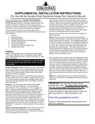
stop functionality.1. Provide external antenna and coaxial wiring to receiver to enhance radiocontrol reception.L. Provide auxiliary chain hoist: for emergency manual operation while disconnectingmotor, without affecting timing of limit switch. Mount disconnect and operator sothey are accessible from floor level. Include interlock device to automaticallyprevent motor from operating when emergency operator is engaged.<strong>PART</strong> 3 EXECUTION3.1 EXAMINATIONA. Examine wall and overhead areas, including opening framing and blocking, withinstaller present, for compliance with requirements for installation tolerances,clearances, and other conditions affecting performance of Work in this Section.1. Proceed with installation only after unsatisfactory conditions have beencorrected.B. If substrate preparation is the responsibility of another installer, notify Architect ofunsatisfactory preparation before proceeding.3.2 PREPARATIONA. Prepare surfaces using the methods recommended by the manufacturer forachieving the best result for the substrate under the project conditions.3.3 INSTALLATIONA. Install overhead doors and track in accordance with approved shop drawings andthe manufacturer's printed instructions.3.4 PROTECTIONA. Protect installed products until completion of project.B. Touch-up, repair or replace damaged products before Substantial Completion.END OF <strong>SECTION</strong><strong>08360</strong>-6