Cybex Total Access Leg Press Owner's and Service ... - GymStore.com
Cybex Total Access Leg Press Owner's and Service ... - GymStore.com
Cybex Total Access Leg Press Owner's and Service ... - GymStore.com

Create successful ePaper yourself
Turn your PDF publications into a flip-book with our unique Google optimized e-Paper software.
www.cybexinternational.<strong>com</strong><strong>Cybex</strong> <strong>Total</strong> <strong>Access</strong> <strong>Leg</strong> <strong>Press</strong>Owner’s <strong>and</strong> <strong>Service</strong> ManualStrength SystemsPart Number 14040-999-4 C
<strong>Cybex</strong> <strong>Total</strong> <strong>Access</strong> <strong>Leg</strong> <strong>Press</strong>Owner’s <strong>and</strong> <strong>Service</strong> ManualStrength SystemsPart Number 14040-999-4 C<strong>Cybex</strong> ® <strong>and</strong> the <strong>Cybex</strong> logo are registered trademarks of <strong>Cybex</strong> International, Inc.VR3 ® <strong>and</strong> its mark are registered trademarks of <strong>Cybex</strong> International,Inc.DISCLAIMER: <strong>Cybex</strong> International, Inc., makes no representations or warranties regarding the contents of this manual. We reserve the right torevise this document at any time or to make changes to the product described within it without notice or obligation to notify any person of suchrevisions or changes.© Copyright 2010, <strong>Cybex</strong> International, Inc. All rights reserved.Printed in the United States of America.10 Trotter Drive Medway, MA 02053 • 508-533-4300 • FAX 508-533-5183www.cybexinternational.<strong>com</strong> • techhelp@cybexintl.<strong>com</strong> • 14040-999-4 C • March 2010
Table of ContentsFront PagesTable of Contents . ............... iDeclaration of Conformity ......... ii1 SafetySafety ......................... 1-1Safety Guidlines <strong>and</strong> Practices . .... 1-2Warning/Caution Decals .......... 1-3Regular Maintenance Activities . .... 1-6Using Proper Form .............. 1-62 ExercisesIntended Use . . . . ............... 2-1Instructions . . . . . . . . . . . . . . . . . . . 2-13 Customer <strong>Service</strong>Contacting <strong>Service</strong> .............. 3-1Ordering parts .................. 3-1Return Material Authorization (RMA) . 3-2Damaged Parts ................. 3-34 Assembly . . . . . . . . . . . . . . . . . . . . . 4-15 MaintenanceDaily Procedures ................ 5-1Weekly Procedures .............. 5-4Yearly Procedures ............... 5-6Environment. . . . . . . . . . . . . . . . . . . 5-7Storage . . . . . . . . . . . . . . . . . . . . . . 5-76 <strong>Service</strong> . . . . . . . . . . . . . . . . . . . . . . . 6-1Page i
Page ii
This page intentionally left blank.
<strong>Cybex</strong> <strong>Total</strong> <strong>Access</strong> 14040 <strong>Leg</strong> <strong>Press</strong> Owner’s Manual1 - SafetySafetyRead the Owner’s Manual carefully before assembling, servicing or using the equipment.It is the responsibility of the facility owner <strong>and</strong>/or owner of the equipment to instruct users on proper operation of theequipment <strong>and</strong> review all labels.WARNING: Serious injury could occur if these safety precautions are not observed:User Safety Precautions• Obtain a medical exam prior to beginning an exercise program.• Read <strong>and</strong> underst<strong>and</strong> warning labels <strong>and</strong> user manual prior to exercising. Obtain instructionprior to use.• Keep body <strong>and</strong> clothing free from <strong>and</strong> clear of all moving parts.• Inspect machine prior to use. DO NOT use if it appears damaged or inoperable.• DO NOT attempt to fi x a broken or jammed machine. Notify fl oor staff.• Use the machine only for the intended use. DO NOT modify the machine.• Be sure that the weight pin is <strong>com</strong>pletely inserted. Use only the pin provided by the manufacturer.If unsure seek assistance.• Never pin the weights in an elevated position. DO NOT use the machine if found in this condition.See assistance from fl oor staff.• Children must not be allowed near these machines. Teenagers must be supervised.• DO NOT use if guards are missing or damaged.• DO NOT use dumbbells or other incremental weights, except those provided by the manufacturer.• Inspect all cables <strong>and</strong> belts <strong>and</strong> connections prior to use. DO NOT use if any <strong>com</strong>ponents are worn, frayed ordamaged.• DO NOT remove any labeling from equipment. Replace any damaged labels.• Stop exercising if you feel faint, dizzy or experience pain at any time while exercising <strong>and</strong> consult yourphysician.Facility Safety Precautions• Read the Owner’s Manual carefully before assembling, servicing or using the equipment.• Securely anchor each machine to the fl oor using the anchor holes provided in each machine.NOTE: <strong>Cybex</strong> is not responsible for the actual anchoring of equipment. Consult with a professionalcontractor.NOTE: Use fasteners having a minimum of 500 lbs. tensile capacity (3/8” grade 2 bolts or better).NOTE: If legs/frame does not contact surface, DO NOT pull down with anchors. Shim anyleg or frame not in contact with surface using fl at washers.SafetyPage 1-1
<strong>Cybex</strong> <strong>Total</strong> <strong>Access</strong> 14040 <strong>Leg</strong> <strong>Press</strong> Owner’s Manual• Make sure that each machine is set up <strong>and</strong> operated on a solid level surface. Do not install equipment on anuneven surface.• Make sure that all users are properly trained on how to use the equipment.• Make sure there is enough room for safe access <strong>and</strong> operation of the equipment.• Perform regular maintenance checks on the equipment. Also pay close attention to all areas most susceptible to wear,including (but not limited to) cables, pulleys, belts <strong>and</strong> grips.• Immediately replace worn or damaged <strong>com</strong>ponents. If unable to immediately replace worn or damaged <strong>com</strong>ponentsthen remove from service until the repair is made.• Use only <strong>Cybex</strong> supplied <strong>com</strong>ponents to maintain/repair the equipment.• Keep a repair log of all maintenance activities.• Inspect all cables <strong>and</strong> belts <strong>and</strong> connections prior to use. DO NOT use if any <strong>com</strong>ponents are worn, frayed ordamaged.NOTE: It is the sole responsibility of the user/owner or facility operator to ensure that regular maintenance is performed.Safety Guidelines And Practices<strong>Cybex</strong> re<strong>com</strong>mends that all fi tness equipment be used in a supervised area. It is re<strong>com</strong>mended that the equipment belocated in an access controlled area. Control is the responsibility of the owner. The extent of control is at the discretion ofthe owner.It is the responsibility of the purchaser/user of <strong>Cybex</strong> products to read <strong>and</strong> underst<strong>and</strong> the owner’s manual, <strong>and</strong> warninglabels; as well as instruct all individuals, whether end users or supervising personnel, on proper usage of the equipment.PROPER USAGE:Use machine only as described in the manual. Failing to follow proper instructions may result in injury.Do Not Lean Against or Pull On the framework, weight stack, or any <strong>com</strong>ponent, whether machine is at rest or in use.Inappropriate or improper use may result in injury to users or third parties (byst<strong>and</strong>ers).Do not use machine if it is not located on a solid level surface or is improperly installed.Provide an adequate safety perimeter between the machine, walls <strong>and</strong> other equipment to ensure that the facility has theproper clearance for usage <strong>and</strong> training.SECURING EQUIPMENT:The machine has holes in the feet, which allow for ease in anchoring to the fl oor. <strong>Cybex</strong> strongly re<strong>com</strong>mends that,to eliminate rocking, tipping or falling over due to incorrect usage <strong>and</strong> misuse, equipment be secured to a solid, levelsurface.1. The solid, level surface should not deviate more than 1/8” over a 10’ distance or as defi ned <strong>and</strong> required by localbuilding <strong>and</strong> architectural codes.2. Anchoring of equipment must be <strong>com</strong>pleted by a qualifi ed licensed contractor.SafetyPage 1-2
<strong>Cybex</strong> <strong>Total</strong> <strong>Access</strong> 14040 <strong>Leg</strong> <strong>Press</strong> Owner’s Manual3. Anchoring holes are provided on the feet of the frame. All anchoring locations must be used when anchoring theequipment to the fl oor.4. Due to the wide variation of fl ooring on which machines may be anchored or installed, verify anchoring method <strong>and</strong>anchoring fasteners with a qualifi ed <strong>and</strong> licensed contractor.5. A minimum pull out force of 220 lbs/100 kgs is required for each anchor position..6. Do not use machine until it is properly anchored.MAINTENANCE:Preventative maintenance allows proper equipment operation <strong>and</strong> reduces the risk of injury. Perform the maintenancerequirements as specifi ed in the manual.STANDARD COMPLIANCE:<strong>Cybex</strong> products meet or exceed applicable ASTM <strong>and</strong> EN St<strong>and</strong>ards.Warning/Caution DecalsWarning decals indicate a potentially hazardous situation, which, if not avoided, could result in death or serious injury.Caution decals indicate a potentially hazardous situation, which, if not avoided, could result in minor or moderate injury.The warning <strong>and</strong> caution decals are shown on the following page. The diagrams following the decals show where eachdecal is located.SafetyPage 1-3
<strong>Cybex</strong> <strong>Total</strong> <strong>Access</strong> 14040 <strong>Leg</strong> <strong>Press</strong> Owner’s ManualABCCAUTIONKeep away from movingparts. Failure to do so couldresult in personal injury.8500-026-44605-381-4 ASafetyPage 1-4
<strong>Cybex</strong> <strong>Total</strong> <strong>Access</strong> 14040 <strong>Leg</strong> <strong>Press</strong> Owner’s Manual<strong>Leg</strong> <strong>Press</strong> - 14040AC(both sides)B(both sides)C(both sides)DescriptionPart No.A. Warning Label....................4605-381-4B. Caution Decal.....................8500-025-4C. Caution Decal.....................8500-026-4SafetyPage 1-5
<strong>Cybex</strong> <strong>Total</strong> <strong>Access</strong> 14040 <strong>Leg</strong> <strong>Press</strong> Owner’s ManualRegular Maintenance ActivitiesPreventative maintenance activities must be performed to maintain normal operation of your equipment.Keeping a log sheet of all maintenance actions will assist you in staying current with all preventativemaintenance activities. The preventative maintenance actions are described in detail in Chapter 5.Briefl y, they include:Daily1. Clean upholstery.Weekly1. Inspect all nuts <strong>and</strong> bolts for looseness. Tighten as required.2. Inspect all cables <strong>and</strong> belts for damage or wear (see Chapter 5). If a cable or belt is wornor damaged, immediately discontinue use until cable or belt has been replaced.3. Check for worn h<strong>and</strong>les, worn snap links, <strong>and</strong> worn warning labeling. Replace all worn partsimmediately.4. Inspect for loose or worn grips. Replace all worn grips immediately.5. Inspect weight stacks for proper alignment <strong>and</strong> operation. Correct all improper alignment<strong>and</strong> operation issues immediately.6. Lubricate guide rods using automotive engine oil only.Yearly1. Replace all cables <strong>and</strong> belts at least annually.Using Proper FormBefore working out, read <strong>and</strong> underst<strong>and</strong> the exercises located on the placard <strong>and</strong> in Chapter 2.SafetyPage 1-6
<strong>Cybex</strong> <strong>Total</strong> <strong>Access</strong> Owner’s Manual2 - ExerciseIntended UseMUSCLES USEDThe intended use of this equipment is to aid orimprove general physical fi tness <strong>and</strong> exercise. For<strong>com</strong>mercial use.InstructionRead <strong>and</strong> underst<strong>and</strong> all instructions <strong>and</strong> warningsprior to using this machine. See Chapter 1, Safety, inthe Owner’s Manual or consult with fl oor staff.Quadriceps, Gluteus Maximus,HamstringsSTARTFINISHNOTE: Motion Developed: Hip Extension, Knee ExtensionNOTE: Do not turn knob when weight stack is elevated.NOTE: All adjustment points on the machine have yellow h<strong>and</strong>les or knobs.NOTE: See next page for “Set Up” <strong>and</strong> “Movement.”ExercisePage 2-1
<strong>Cybex</strong> <strong>Total</strong> <strong>Access</strong> Owner’s ManualSet Up - Consult floor staff if assistance is required.1. Adjust seat to <strong>com</strong>fortable start position for knees <strong>and</strong> hips.2. Position feet <strong>com</strong>fortably on foot plates with toes pointed slightly outward.Movement1. Push into foot plate until legs are straight.NOTE: Do not hyperextend knees.ExercisePage 2-2
<strong>Cybex</strong> <strong>Total</strong> <strong>Access</strong> Owner’s Manual3 - Customer <strong>Service</strong>Contacting <strong>Service</strong>Hours of phone service are Monday through Friday from 8:30 a.m. to 6:00 p.m. Eastern St<strong>and</strong>ard Time.For <strong>Cybex</strong> customers living in the USA, contact <strong>Cybex</strong> Customer <strong>Service</strong> at 888-462-9239.For <strong>Cybex</strong> customers living outside the USA, contact <strong>Cybex</strong> Customer <strong>Service</strong> at 508-533-4300or fax 508-533-5183.Find information on the web at www.e<strong>Cybex</strong>.<strong>com</strong> or by e-mail at techhelp@cybexintl.<strong>com</strong>.Ordering PartsFax your order to 508-533-5183. To speak with a customer service representative, call 888-462-9239 (forcustomers living within the USA) or 508-533-4300 (for customers outside the USA). You may also contactus through e-mail at techhelp@cybexintl.<strong>com</strong>.Having the following information ready when calling will assist our <strong>Cybex</strong> representatives in serving you.• Unit Serial Number• Product NameThe unit serial number <strong>and</strong> product name can be found on the serial number decal. See Chapter 6 forexact location of serial number decal.• Part Description• Part NumberPart descriptions <strong>and</strong> part numbers are located in Chapter 6 of this manual.• Shipping Address• Contact NameIn addition to your shipping address <strong>and</strong> contact name, your account number is helpful but not required.Customer<strong>Service</strong>Page 3-1
<strong>Cybex</strong> <strong>Total</strong> <strong>Access</strong> Owner’s ManualReturn Material Authorization (RMA)The Return Material Authorization (RMA) system outlines the procedures to follow when returning materialfor placement, repair or credit. The system assures that returned materials are properly h<strong>and</strong>led <strong>and</strong> analyzed.Follow the following procedures carefully.Contact your authorized <strong>Cybex</strong> dealer on all warranty-related matters. Your local <strong>Cybex</strong> dealer will requesta RMA from <strong>Cybex</strong>, if applicable. Under no circumstances will defective parts or equipment be accepted by<strong>Cybex</strong> without proper RMA <strong>and</strong> an Automated Return <strong>Service</strong> (ARS) label.1. Call the Customer <strong>Service</strong> Hotline listed above for the return of anything that is defective.2. Provide the technician with a detailed description of the problem you are having or the defect in the itemyou wish to return.3. Provide the model <strong>and</strong> serial number of your <strong>Cybex</strong> equipment.4. At <strong>Cybex</strong>’s discretion, the technician may request that you return the problem part(s) to <strong>Cybex</strong> for evaluation<strong>and</strong> repair or replacement. The technician will assign you a RMA number <strong>and</strong> will send you an ARS label.The ARS label <strong>and</strong> the RMA numbers must be clearly displayed on the outside of the package that containsthe item(s) to be returned. Include the description of the problem, the serial number of the <strong>Cybex</strong> equipment<strong>and</strong> the name <strong>and</strong> address of the owner in the package along with the part(s).5. Forward the package through UPS to <strong>Cybex</strong>.Attn: Customer <strong>Service</strong> Department<strong>Cybex</strong> International, Inc.1975 24th Ave SWOwatonna, MN 55060NOTE: Merch<strong>and</strong>ise returned without an RMA number on the outside of the package or shipments sent CODwill not be accepted by the <strong>Cybex</strong> receiving department.Customer<strong>Service</strong>Page 3-2
<strong>Cybex</strong> <strong>Total</strong> <strong>Access</strong> Owner’s ManualDamaged PartsMaterials damaged in shipment should not be returned for credit. Shipping damages are the responsibilityof the carrier (UPS, Federal Express, trucking <strong>com</strong>panies, etc.)Apparent Damage - Upon receipt of your shipment, check all items carefully. Any damage seen with avisual check must be noted on the freight bill <strong>and</strong> signed by the carrier’s agent. Failure to do so will resultin the carriers refusal to honor your damage claim. The carrier will provide you with the required forms forfi ling such claims.Concealed Damage - Damage not seen with a visual check upon receipt of a shipment but noticed latermust be reported to the carrier as soon as possible. Upon discovery of the damage, a written or phonerequest to the carrier asking them to perform an inspection of the materials must be made within tendays of the delivery date. Keep all shipping containers <strong>and</strong> packing materials as they will be needed inthe inspection process. The carrier will provide you with an inspection report <strong>and</strong> the necessary forms forfi ling a concealed damage claim. Concealed damage claim is the carrier’s responsibility.Customer<strong>Service</strong>Page 3-3
<strong>Cybex</strong> <strong>Total</strong> <strong>Access</strong> Owner’s ManualThis page intentionally left blankCustomer<strong>Service</strong>Page 3-4
<strong>Cybex</strong> <strong>Total</strong> <strong>Access</strong> Owner’s Manual4 - AssemblyTOOLS REQUIRED• 7/32” Allen wrench• 1/8” Allen wrench• Medium weight automotive engine oil• Torque wrench• 3/4” WrenchNOTE: Two people will be required for this procedure.NOTE: It is the responsibility of the facility owner/owner of the equipment to ensure that thereis appropriate clearance around each machine to allow for safe use <strong>and</strong> passage.NOTE: Refer to chapter 6 for reference diagrams.1. Read <strong>and</strong> underst<strong>and</strong> all instructions thoroughly before starting any ofthe procedures listed on this instruction sheet.2. Verify you have received the appropriate configuration.A.B.C.D.E.Verify that you received the correct color machine that you ordered.Verify you received the proper weight stack.Verify you received the appropriate owner’s manual.Verify you received the warranty sheet.Verify you received the weight stack decals.3. Move to desired location.4. Remove shipping feet.WARNING: Use extreme caution when removing shipping cones <strong>and</strong> installing feet.Failure to do so could result in injury.A.B.C.With an assistant, carefully remove each (st<strong>and</strong>ard) cone-shaped shipping supportusing a 3/4” socket or wrench.Cut shipping tie securing top weight.Carefully place rubber feet (supplied with machine) on each foot of the frame.5. Installing the weight stack.A.B.If weight stack is already installed, proceed to step 9.Using a 1/8” Allen wrench, remove the two Button Head Socket Cap Screws (BHSCS) securing thebottom bracket to the frame. NOTE: Do not remove middle BHSCS securing shroud to bottom bracket.C. Remove the remaining BHSCS securing the back shroud to the frame. NOTE: After fi nal BHSCSis removed shroud will slide down to the fl oor with bottom support bracket attached.D.Carefully slide shroud out of machine.AssemblyPage 4-1
<strong>Cybex</strong> <strong>Total</strong> <strong>Access</strong> Owner’s ManualE.Slide spring loaded top guide rod cap down guide rod until guide rod cap is clearof frame. NOTE: Top guide rod cap is spring loaded.F. Slowly release grasp of guide rod cap. NOTE: Guide rod cap contains a <strong>com</strong>pression springthat will fl y if grasp is not released slowly.G.H.I.J.K.L.Remove guide rod cap <strong>and</strong> spring <strong>and</strong> set aside.Repeat steps 5F-5H for other rod guide.Carefully lean guide rods slightly outward, away from machine to clear pulley.NOTE: Excessive pressure on guide rods may damage lower guide rod caps.Slide top weight up <strong>and</strong> out of machine <strong>and</strong> carefully set it aside.Wipe guide rods clean over entire length. Lubricate with light coating of mediumweight automotive engine oil.Have an assistant hold the guide rods vertical.M. Carefully align weight plate over guide rods <strong>and</strong> slowly lower weight plate. NOTE: When installing weightplates, position plates so wide edges of bushing face upward <strong>and</strong> narrow edges of bushing face downward.See Figures 1A <strong>and</strong> 1B.N.Repeat step 5M-5N to install each weight plate.CORRECTWIDE bushingedge facesupwardWRONGNOTE: The narrow bushingedge must face downward.NARROWbushing edgeFigure 1AFigure 1BO.P.Q.Slide top weight over guide rods.Place springs <strong>and</strong> guide rod caps on guide rods (removed from step 5G).Compress guide rod caps <strong>and</strong> ailgn guide rod caps with weight frame holes <strong>and</strong> secure in place.NOTE: Guide rod caps must snap or lock into weight frame holes.AssemblyPage 4-2
<strong>Cybex</strong> <strong>Total</strong> <strong>Access</strong> Owner’s Manual6. Belt Routing.A.Verify belt is routed through top of pulley bracket <strong>and</strong>then route end of belt down to the top weight.B. Carefully lift top weight <strong>and</strong> verify that the position of thebelt clamp (on the top weight) is aligned properly with thetop pulley bracket.Correct belt routingInsertBeltStemWrong belt routingInsertBeltStemC.D.E.Slide belt through slot in belt clamp.Verify belt <strong>and</strong> insert are installed properly, as shown inFigure 2A. NOTE: Do not install the insert backwards asshown in Figure 2B.Pull belt tight <strong>and</strong> secure belt to clamp with the two setscrews. NOTE: Torque set screws 300-350 in./lbs.Figure 2AFrontFigure 2BF.Place weight stack pin in each plate to verify properinstallation.BackG.Without selecting any resistance, lift top weight up<strong>and</strong> down (simulating normal operation).Figure 3H.I.Have an assistant verify that the belt is movingsmoothly <strong>and</strong> is routed straight from the toppulley bracket to the top weight belt clamp.Turn the Increment Weight Adjusting Knob toselect 0 lbs or 0 kg.Guide Rod7. Install back shrouds.A.Carefully place shroud into position.B. Starting at the bottom replace the twoBHSCS (removed in step 5D) to securebottom support bracket to the shroud. Installbut do not tighten remaining BHSCS securingshroud.C.Tighten all BHSCS.Weight StackFigure 4Pounds1 9.02 18.034 36.05 45.06 54.07 63.08 72.09 81.010 90.099.0Kilograms8. Install weight plate decals.A. Slowly <strong>and</strong> carefully peel off back side of decal. NOTE: When peeling off back cover,make sure that the decals remain attached to the front sticker. Figure 3.B. Insert a guide pin through each hole of the template. NOTE: A guide pin can be anything that fi tsthrough the weight stack hole, such as a weight stack selector pin.C.D.Carefully align decal <strong>and</strong> rub it onto weight plates.Carefully remove front side, leaving decals adhering to weight plates. See Figure 4.AssemblyPage 4-3
<strong>Cybex</strong> <strong>Total</strong> <strong>Access</strong> Owner’s ManualNOTE: It is important that you perform regular inspection <strong>and</strong> maintenance activities on your equipment.See the CYBEX Owner’s Manual for inspection <strong>and</strong> maintenance activities. If you do not have aCYBEX Owner’s Manual or if you have any questions or concerns, call CYBEX Customer Relationsat 888-462-9239.9. Verify proper operation10. Securely anchor machine to the floor.A.Securely anchor machine to the fl oor usingthe anchor holes provided in each machine.NOTE: <strong>Cybex</strong> is not responsible for the actual anchoring of equipment. Consult with a professional contractor.NOTE: Use fasteners having a minimum of 500 lbs. tensile capacity (3/8’’ grade 2 bolts or better).NOTE: If legs/frame does not contact surface, DO NOT pull down with anchors. Shim any leg orframe not in contact with surface using fl at washers.AssemblyPage 4-4
<strong>Cybex</strong> <strong>Total</strong> <strong>Access</strong> Owner’s ManualChapter 5 - MaintenanceAll preventive maintenance activities must be performed on a regular basis. Performingroutine preventive maintenance actions can aid in providing safe, trouble-free operation of all <strong>Cybex</strong>Strength Systems equipment.NOTE:<strong>Cybex</strong> is not responsible for performing regular inspection <strong>and</strong> maintenance actionsfor your machines. Instruct all personnel in equipment inspection <strong>and</strong> maintenanceactions <strong>and</strong> also in accident reporting/recording. <strong>Cybex</strong> phone representatives areavailable to answer any questions or concerns that you may have.NOTE: All inspections <strong>and</strong>repairs must beperformed by trainedservice personnel only.<strong>Cybex</strong> will void warranty ifnon-<strong>Cybex</strong> replacement partsare used.Daily Procedures1. Upholstery - Wipe down all upholstery as per the re<strong>com</strong>mendations listed below for light soiling <strong>and</strong> moredifficult stains.Light Soiling• A solution of 10% household liquid dish soap with warm water applied with a soft damp cloth.• If necessary, a solution of liquid cleanser <strong>and</strong> water applied with a soft bristle brush. Wipe away theresidue with a water dampened cloth.MaintenancePage 5-1
<strong>Cybex</strong> <strong>Total</strong> <strong>Access</strong> Owner’s ManualMore Difficult Stains• Dampen a soft white cloth with a solution of 10% household bleach (sodium hypochlorite), 90% water.Rub gently. Rinse with a water dampened cloth to remove bleach concentration.• The same procedure can be used with full strength household bleach, if necessary.• Allow bleach to puddle on the affected area or apply with a soaked cloth for approximately 30 minutes.Rinse with a water dampened cloth to remove any remaining bleach concentration.Alternative Method for Difficult Stains• Dampen a soft white cloth with rubbing alcohol <strong>and</strong> rub gently. Rinse with a water dampened cloth toremove any remaining rubbing alcohol concentration.NOTE: To restore luster, a light coat of spray furniture wax can be used. Apply for 30 seconds <strong>and</strong> followwith a light buffing using a clean white cloth.Please Review CarefullyWhen using strong cleaning agents such as rubbing alcohol or bleach, it is advisable to first test in an inconspicuousarea. Other cleaning agents may contain harsh or unknown solvents <strong>and</strong> are subject to formulachanges by the product manufacturer without notice. Should you desire to use other cleaning agents, carefullytry them in an inconspicuous area to determine potential damage to the material. Never use harsh solvents orcleaners which are intended for industrial applications. To clean stained or soiled areas, a softwhite cloth is re<strong>com</strong>mended. Avoid use of paper towels.Cleaning products may be harmful/irritating to your skin, eyes, etc. Use protective gloves <strong>and</strong> eye protection. Donot inhale or swallow any cleaning product. Protect surrounding area/clothing from exposure. Use in a well ventilatedarea. Follow all product manufacturer’s warnings. CYBEX <strong>and</strong> its vendors cannot be held responsible fordamage or injuries resulting from the use or misuse of cleaning products.2. Frames - Wipe down all frames using a mild solution of warm water <strong>and</strong> car wash soap. Be sure to drythoroughly. AVOID acid or chlorine based cleaners <strong>and</strong> also cleanerscontaining abrasives as these could scratch or damage the equipment.3. Chrome - Clean chrome tubes, first using chrome polish <strong>and</strong> then using a car wax seal.Neutral cleaners with a pH between 5.5 <strong>and</strong> 8.5 are re<strong>com</strong>mended. Be sure to drythoroughly. AVOID acid or chlorine based cleaners <strong>and</strong> also cleaners containing abrasivesas these could scratch or damage the equipment.MaintenancePage 5-2
<strong>Cybex</strong> <strong>Total</strong> <strong>Access</strong> Owner’s Manual4. Guidelines for cleaning front panel:• Use clean soft cloths or sponges for application of cleaners <strong>and</strong> again for washing <strong>and</strong> rinsing.• Follow up the application with warm water rinse.• Don’t use abrasives or high alkaline cleaners.• Don’t leave cleaners on for long periods, wash immediately.• Don’t apply cleaners in direct sunlight or at elevated temperatures.• Don’t use scrapers, squeegees or razors.• Don’t clean with gasoline.5. Compatible Cleaners <strong>and</strong> Detergents:• Formula 409• Top Job• Joy• Palmolive• Windex with Ammonia D6. To Minimize Fine or Hairline Scratches:Mild automotive polish applied <strong>and</strong> removed with a soft, clean cloth will help fill scratches.7. Suggested Polishes:• Johnson Paste Wax• Mirror Glaze #10 Plastic Polish (by Mirror Bright Polish Co.)• Novus Plastics Polish #1, #2 (by Novus Inc.)MaintencePage 5-3
<strong>Cybex</strong> <strong>Total</strong> <strong>Access</strong> Owner’s ManualWeekly Procedures1. Check all nuts <strong>and</strong> bolts for looseness. Tighten as required.2. Inspect all belts (entire length) for any non-uniformity <strong>and</strong> wear.Immediately replace belt if any of the following conditions are present:MaintenancePage 5-4
<strong>Cybex</strong> <strong>Total</strong> <strong>Access</strong> Owner’s Manual3. Some machines use cables in addition to belts. Inspect all cables for wear or damage <strong>and</strong> propertension. When inspecting cables, run your fingers on the cable, paying particularattention to bends in the cable <strong>and</strong> attachment points.Replace all worn cables immediately. The following conditions may indicate a worncable:• A tear or crack in the cable sheath that exposes the cable. See Figure 1Figure 1• A kink in the cable. See Figure 2.Figure 2• A curled sheath. See Figure 3.Figure 3• “Necking”, a stretched cable sheath. See Figure 4.Figure 4MaintenancePage 5-5
<strong>Cybex</strong> <strong>Total</strong> <strong>Access</strong> Owner’s Manual4. Inspect bars <strong>and</strong> h<strong>and</strong>les for wear, paying particular attention to tab area connectingpoints.Replace all worn h<strong>and</strong>les immediately.5. Inspect snap links for proper latching (indicates wear).Replace all worn snap links immediately.6. Inspect for loose or worn grips.Replace all loose or worn grips immediately.7. Inspect all labeling for readability. This includes instructional placards, warning <strong>and</strong> caution decals.Replace all worn labeling immediately.8. Inspect all weight stacks for proper alignment <strong>and</strong> operation.Correct all improper alignment <strong>and</strong> operation issues immediately.9. Wipe Weight Stack Guide Rods clean over entire length. Lubricate with a light coat of mediumweight automotive engine oil.Yearly Procedures1. Replace all belts <strong>and</strong> cables at least annually.MaintenancePage 5-6
<strong>Cybex</strong> <strong>Total</strong> <strong>Access</strong> Owner’s ManualEnvironmentStatic Electricity - Depending upon where you live, you may experience dry air, causing a <strong>com</strong>monexperience of static electricity. This may be especially true in the winter time. You may notice a staticbuild-up just by walking across a carpet <strong>and</strong> then touching a metal object. The same can hold true while workingout on your unit. You may experience a shock due to the build-up of static electricity on your body <strong>and</strong> thedischarge path of the unit. If you experience this type of situation, you may want to increase the humidity to a<strong>com</strong>fortable level through the use of a humidifier.Humidity - The unit is designed to function normally in an environment with a relativehumidity range of 30% to 75%.NOTE: Do not install or use the unit in an area of high humidity, such as in the vicinity of a steam room, sauna,indoor pool or outdoors. Exposure to extensive water vapor, chlorine <strong>and</strong>/or bromine could adverselyaffect the electronics as well as other parts of the machine.Temperature - The unit is designed to function normally in an environment with an ambient temperature rangeof 50 o F (10 o C) to 104 o F (40 o C) degrees.StorageHumidity - The unit can be shipped <strong>and</strong> stored in an environment with a relative humidity range of 10% to 90%.NOTE: Do not store the unit in an area of high humidity, such as in the vicinity of a steam room, sauna, indoorpool or outdoors. Exposure to extensive water vapor, chlorine <strong>and</strong>/or bromine could adversely affect theelectronics as well as other parts of the machine.Temperature - The unit can be shipped <strong>and</strong> stored in an environment with an ambient temperature range of 32 oF (0 o C) <strong>and</strong> 140 o F (60 o C) degrees.MaintenancePage 5-7
<strong>Cybex</strong> <strong>Total</strong> <strong>Access</strong> Owner’s ManualThis page intentionally left blankMaintenancePage 5-8
<strong>Cybex</strong> <strong>Total</strong> <strong>Access</strong> Owner’s Manual6 - <strong>Service</strong>Please refer to the next several pages for parts lists, exploded-view diagrams <strong>and</strong> cable<strong>and</strong> belt routing diagrams.NOTE: All inspections<strong>and</strong> repairs must beperformed by trainedservice personnel only.<strong>Cybex</strong> will void warranty ifnon-<strong>Cybex</strong> replacement partsare used.<strong>Service</strong>Page 6-1
<strong>Cybex</strong> <strong>Total</strong> <strong>Access</strong> Owner’s ManualThis page intentionally left blank<strong>Service</strong>Page 6-2
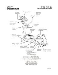
<strong>Cybex</strong> <strong>Total</strong> <strong>Access</strong> 14040 <strong>Leg</strong> <strong>Press</strong> Owner’s ManualLEG PRESSAHBONPDGKFE (Both Sides)I,JL (Both Sides)CE (Both Sides)NOTE: See exploded-view diagram for location of M (serial number decal).DESCRIPTIONPART NO.A. Placard Decal .................... 14040-598-4B. Placard Decal .................... 14040-599-4C. Caution Decal .................... 8500-025-4D. Warning Label ................... 4605-381-4E. Caution Decal .................... 8500-026-4F. Weight Stack Belt 240.75”.. GB000202G. Weight Stack Belt 36”......... GB000202H. Water Bottle Holder............. 13000-400I. Back Pad w/Wear Cover ..... 4800-184J. Wear Cover .......................... 4800-187K. Seat Pad .............................. 4800-188L. Grip .....................................4605-507M. Serial Number DecalN. Weight Selector Pin............ BH030207O. Non-Slip.............................. 11040-562P. Increment Weight Decal...... 14000-407-4<strong>Service</strong>Page 6-3
<strong>Cybex</strong> <strong>Total</strong> <strong>Access</strong> 14040 <strong>Leg</strong> <strong>Press</strong> Owner’s ManualITEM QTY PART NO. DESCRIPTION1 2 11040-301 CLAMP BLOCK INSERT2 1 11040-562 NON-SLIP3 1 11040-568 CLAMP BLOCK INSERT4 1 11090-314 P/PIN,DETENT5 2 11090-369 SHAFT, PIVOT6 2 11090-374 END CAP7 2 11090-376 RING, HANDLE GRIP8 1 11090-385 GRIP9 1 12000-467 PULLEY COVER10 1 12000-385 PANEL INSERT11 2 12000-388 EXTRUSION, INC WT CHANNEL12 1 12000-389 CHANNEL, INCREMENT WEIGHT13 1 12000-390 CHANNEL, INCREMENT WEIGHT14 1 12000-395 TOP CAP15 2 12000-396 END CAP16 4 12000-398 SPACER17 1 12040-200 W/ FRAME18 1 12040-201 W/PIVOT19 1 12040-202 W/ FOOT PLATE20 1 12040-203 W/LINK21 1 12040-206 P/CAM BOLT22 1 12040-207 W/GUARD23 1 12040-208 W/BELT CLAMP24 4 12040-323 ROLLER25 5 12040-324 SPACER26 2 12040-336 WT ROD .625 DIA X 68.62527 1 12040-347 BLOCK28 1 12040-348 EXTENSION SPRING 20.25 LONG29 2 12040-354 SPACER30 4 12090-322 FOOT PAD31 2 12102-330 INSERT, INCREMENT WEIGHT32 4 12102-331 INSERT, INCREMENT WEIGHT33 2 12210-347 GUIDE ROD CAP34 2 12210-348 GUIDE ROD CAP35 1 13000-400 HOLDER, WATER BOTTLE36 1 13000-402 MOUNT, WATER BOTTLE HOLDER37 1 14040-009 TOP WEIGHT ASSY 2538 1 14040-204 W/SEAT39 1 14040-202 W/ HANDLE, PIVOT40 1 14040-306 TUBE41 1 14000-400 DECAL, WEIGHT PLATE42 6 4860-332 PLUG, ADJ BEARING43 1 51198 WARRANTY BOOK (NOT SHOWN)44 2 5220-305 2.00 X 4.00 BUMPER45 2 BR030226 RETAINING RING, 1.653 INTERNAL46 1 BS070201 COM SPRING .56 x .66 1.50 LG47 2 BS070208 COMPRESSION SPRING48 1 CM000211 DECAL, PATENT PENDINGITEM QTY PART NO. DESCRIPTION49 6 FB030232 BEARING, RADIAL 17 mm EX RACE50 6 FC030006 TOLERANCE RING 1.575 ID51A 244” 12040-362 WEIGHT STACK BELT .95 WIDE51B 35” GB000202 BELT .95 WIDE52 12 gp000209 PULLEY ASSEMBLY-3.5053 7 HC700415 BHSCS .375-16 X .7554 2 HC700416 BHSCS .375-16 X .87555 8 HC700428 BHSCS .375-16 X 2.2556 10 HC700430 BHSCS .375-16 X 2.5057 1 HD303315 S BOLT .250 X .750 .190-10-2458 1 HD303312 S BOLT .250 X .500 .190-10-2459 2 HF449063 INSERT 3/4 X 1/4-2060 14 HF579000 PANEL FASTNER, 10-24 U TYPE61 2 HN575100 LOCKNUT .190-No 10-2462 29 HN704901 LOCKNUT, .375-16 NYLON63 27 HS347600 WASHER, SAE .37564 10 HT512517 TAP SC 10-24 X 1.00 TYPE WB PNHD PHIL BLK65 1 HT552515 TAP SC NO. 8-16 X .75 PLASTITE PNHD PHIL BLK66 4 HT570410 SCREW, PNH TORX 10-24 X .375, BLK67 14 HX570412 BHSCS, 10-24 X .50, SS68 7 HY740000 SET SCREW69 2 JC620422 BHSCS .250-20 x 1.5070 6 JC700412 BHSCS .375-16 X .5071 5 JC700420 BHSCS .375-16 X 1.2572 1 JC700422 BHSCS .375-16 X 1.5073 4 JC700434 BHSCS .375-16 X 3.0074 4 JS347400 LOCKWASHER, INT TOOTH .37575 2 PP090208 INSERT, PLASTIC 1.75 DIA. RIBBED76 1 PP130002 INSERT, DOMED PLASTIC77 2 PR060003 BUMPER, RECESS78 2 PR060005 BUMPER, WEIGHT79 2 4605-507 GRIP 1.38 OD X .94 ID X 6.50LG80 1 4800-188 SEAT PAD81 1 4800-184 BACKPAD W/WEAR COVER82 1 4800-187 WEAR COVER83 1 14040-598-4 LEG PRESS PLACARD84 1 14040-599-4 LEG PRESS PLACARD85 1 4605-381-4 DECAL, WARNING86 1 14040-999-4 OWNERS MANUAL (NOT SHOWN)87 1 8500-025-4 DECAL, CAUTION88 4 8500-026-4 DECAL, CAUTION89 2 11040-409 BUMPER90 1 11040-216 BELT CLAMP91 1 14000-407-4 INCREMENT WEIGHT DECAL92 1 11040-790 DECAL, MADE IN U.S.A.<strong>Service</strong>Page 6-4
<strong>Cybex</strong> <strong>Total</strong> <strong>Access</strong> 14040 <strong>Leg</strong> <strong>Press</strong> Owner’s Manual14040 VR3 TA MAIN ASSEMBLY5063495704549507063495018 19Torque Set Screws300-350 In/Lbs685344452149507049706355322 62 6251B6250626355555217162 5268 232962Torque Set Screws300-350 In/Lbs296270632050 63495344362287227565675706535758816646436886268Torque Set Screws300-350 In/Lbs166696666 6616 1648Serial Number6252556276864056 5652175562545354<strong>Service</strong>Page 6-5
<strong>Cybex</strong> <strong>Total</strong> <strong>Access</strong> 14040 <strong>Leg</strong> <strong>Press</strong> Owner’s ManualLEG PRESS SEAT ASSEMBLY808182616186962124775539597924637342256965956257975674712587762422563627471405562384263 626263717146 634 624262634263627474 885758737363 632424254273567762 62 62<strong>Service</strong>Page 6-6
<strong>Cybex</strong> <strong>Total</strong> <strong>Access</strong> 14040 <strong>Leg</strong> <strong>Press</strong> Owner’s ManualLEG PRESS PANEL ASSEMBLY156712 14166764646060666067106413151667960666467676067168360608466666060676767649160646767646011606489326032319285601189323267671631<strong>Service</strong>Page 6-7
<strong>Cybex</strong> <strong>Total</strong> <strong>Access</strong> 14040 <strong>Leg</strong> <strong>Press</strong> Owner’s ManualTop Weight Assembly(Light Stack <strong>and</strong> Heavy Stack Configurations)ITEM QTY PART NO. DESCRIPTION ITEM QTY PART NO. DESCRIPTION1 1 11040-366 Top Weight Assembly, Molded2 1 11040-367 Hub, Molded3 2 11040-369 Rod, Linkage4 2 11040-370 Pin5 1 11040-427 Rod6 1 11040-426 Stem7 1 11040-424 Cover Plate8 1 11040-416 Cover, Top Weight9 1 11040-425 Knob10 1 BH030207 Pin, Weight Selector11 1 4700-253 Lifting Post 2512 4 BR030209 External Retaining Ring .18813 2 BR030220 Internal Retaining Ring 1.25014 1 HP016820 Cotter Pin .125 X 1.2515 1 HP266765 Roll Pin, .125 X .93816 2 HS720004 Felt Washer, .641 1.250 .125 T17 4 HT562715 Tap SC NO 10 x .750 F Phil18 4 HT582510 Tap SC NO 10 x .375 PN HDPhil19 2 11040-409 Molded Bumper Pad20 12 11040-572 Guard, Increment Weight21 6 11040-573 Weight Increment22 1 11040-216 Belt Clamp23 1 11040-301 Clamp Block Insert24 1 11040-428 Adjustment Decal25 1 HT552512 Screw, Pan HD Phil HD SelfTapping 8-16 x .50, Type WB26 3 HY740000 Set Screw27 19 4000C101 Weight Plate Light Stack27 24 4000C101 Weight Plate Heavy Stack28 1 12040-020 Light Weight Pack (Not Shown)29 1 12020-021 Heavy Weight Pack (Not Shown)232622TOURQUE SET SCREWS300-350 IN./LBS81212323441161314515256718109242120191117NOTE: Increment weights are locatedin the increment weight channel.See main assembly.<strong>Service</strong>Page 6-827
<strong>Cybex</strong> <strong>Total</strong> <strong>Access</strong> 14040 <strong>Leg</strong> <strong>Press</strong> Owner’s ManualBelt Routing Assembly Detail473352473362625552261265568Torque Set Screws300-350 In/Lbs906356635262 626363 6362375662636263566263785663633478635663563451A<strong>Service</strong>Page 6-9
10 Trotter Drive Medway, MA 02053 • 508-533-4300 • FAX 508-533-5183www.cybexinternational.<strong>com</strong> • Techhelp@cybexintl.<strong>com</strong>