Create successful ePaper yourself
Turn your PDF publications into a flip-book with our unique Google optimized e-Paper software.
<strong>PROFOS</strong>MODULAR SEWAGEPUMP STATIONSwww.pipelife.com
Contents1 Introduction.............................................................................................................................................. 31.1 What is <strong>PROFOS</strong>?..................................................................................................................................... 31.2 Why should we choose <strong>PROFOS</strong>?............................................................................................................ 31.3 <strong>PROFOS</strong> advantages................................................................................................................................ 31.4 <strong>PROFOS</strong> applications?.............................................................................................................................. 41.5 What kind of waste waters can <strong>PROFOS</strong> carry?....................................................................................... 42 According to which standards are <strong>PROFOS</strong> made?............................................................................ 42.1 Why are standards necessary?................................................................................................................. 42.2 What standards <strong>PROFOS</strong> meets?............................................................................................................. 52.3 General requirements for design and realization of SPS........................................................................... 53 Product range.......................................................................................................................................... 63.1 <strong>PROFOS</strong> identification description............................................................................................................ 63.2 Description-identification of pumps used in <strong>PROFOS</strong>............................................................................... 74 What are the composite parts of <strong>PROFOS</strong>?.......................................................................................... 85 <strong>PROFOS</strong> technical characteristics and parameters............................................................................. 105.1 Manhole-draw tank.................................................................................................................................... 105.2 Defining the position and the type of discharging pipe and necessary valves........................................... 115.3 Used pumps and elements in the <strong>PROFOS</strong> stations................................................................................. 115.3.1 General information about the used pumps............................................................................................... 115.3.2 Impeller types of pumps............................................................................................................................. 125.3.3 Material used in the pumps’ construction................................................................................................... 125.3.4 Types of pumps used in <strong>PROFOS</strong>............................................................................................................. 125.3.5 Pipes assembly type.................................................................................................................................. 135.3.6 Control panel............................................................................................................................................. 135.3.7 Level switches........................................................................................................................................... 145.3.8 Additional equipment compatible with <strong>PROFOS</strong>....................................................................................... 146 What is the necessary data for <strong>PROFOS</strong> design?................................................................................ 166.1 Pumps characteristics................................................................................................................................ 166.2 Capacity..................................................................................................................................................... 176.3 Pressure.................................................................................................................................................... 186.4 Velocity...................................................................................................................................................... 186.5 Pump’s wearing out factors....................................................................................................................... 186.6 Draw tank................................................................................................................................................... 196.6.1 General requirements for design............................................................................................................... 196.6.2 Parameters defining the working (efficient) volume of the draw tank........................................................ 196.7 <strong>PROFOS</strong> pressure pipeline-discharging pipe............................................................................................ 206.8 Project documentation preparation............................................................................................................ 207 <strong>PROFOS</strong> assembly.................................................................................................................................. 227.1 Introduction and general requirements...................................................................................................... 227.2 <strong>PROFOS</strong> laying advantages...................................................................................................................... 227.3 <strong>PROFOS</strong> assembly requirements............................................................................................................. 238 Station start up, exploitation and warranty........................................................................................... 268.1 Putting into operation................................................................................................................................. 268.2 <strong>PROFOS</strong> start up and setting-up............................................................................................................... 268.3 <strong>PROFOS</strong> warranty..................................................................................................................................... 269 Additional elements and accessories compatible with <strong>PROFOS</strong> ...................................................... 272<strong>Pipelife</strong>www.pipelife.com
1. Introduction1.1. What is <strong>PROFOS</strong>?<strong>PROFOS</strong> is a new product of <strong>Pipelife</strong> Bulgaria which is destined to fill up the scale of products in the infrastructure sewage nets andsystems.<strong>PROFOS</strong> modular sewage pump station for waste and drainage waters is offered as a final product ready for laying, created due tothe cooperation between <strong>Pipelife</strong> Bulgaria and Grundfos.1.2. Why should we choose <strong>PROFOS</strong>Very often using sewage pump station is economically more profitable solution than establishing a treatment facility or than unnecessary,groundless digging of the sewage net.They have become an efficient solution allowing the designers to choose the most appropriate configuration and type of constructionwhich form a completed SPS (Sewage Pump Station).Using concrete tanks or manholes for SPS has become necessary due to the following arguments:● An opportunity to be assembled at the spot● Relatively low price● Easy assembling in/outletsThis doesn’t make them preferred by the investors in comparison with their disadvantages:● Bad leak-tightness● Low connections strength● Fragility● Especially high costs for transportation and assemblyThe necessary requirements for leak-tightness in accordance with the European standards, the growing influence of ecological factorsand the implementation of modern materials and technology “put pressure” on the investors to turn to thermo-plastic systems formaking of tanks or manholes for sewage pump stations.1.3. <strong>PROFOS</strong> advantages● Final ready product-intelligent construction and compact design.● Ready design solution which meets all your requirements.● A broad scale of offers.● Saves time and money.● Easy connection to the existing sewage net.● Leak-tightness and strength-high quality materials.● Low exploitation costs and long life.● Small size, low weight-easy transport and assembly.● Big depth of laying.● Stability and reliability.● Long life at work with aggressive liquids.● Low noise level.1.4. <strong>PROFOS</strong> applications?● When draining homes, buildings, complexes, small industry plants and others which are situated low in relation to the sewage net.● For reducing the digging of the sewage net.● For pumping of waste and atmospheric waters from low situated regions.● For getting over hills, water currents, roads railways and others● For pumping of waters from rainwater tanks.● For pumping of waste waters towards treatment stations, water tanks.<strong>Pipelife</strong>www.pipelife.com3
1.5. What kind of waste waters can <strong>PROFOS</strong> carry?● Drainage waters.● Atmospheric waters.● Waste waters from buildings, complexes and so on.● Technology waters from different industry applications.● Untreated “raw” waters towards WWTP.● Waste waters with high concentration of fibres.● Waste waters with gasses dissolved in them.2. According to which standards are <strong>PROFOS</strong> made?2.1. Why are standards necessary?The standards are a combination of rules and norms based on practical and theoretical observations and research of the technicalparameters which the products should meet. They define minimal requirements for quality of the specific product. At the same timethey guarantee compatibility of products made from different manufacturers.All this makes the standard extremely important because it guarantees to all the parties: designers, engineers, architects constructionclients, control authorities and others that the product they use meets the specific application and possesses all the necessary qualitiesfor allowing an unhindered, flawless and long-term exploitation.2.2. 2.2. What standards <strong>PROFOS</strong> meets?<strong>Pipelife</strong>’s Sewage pump stations (SPS) <strong>PROFOS</strong> and its composite elements are sized and standardized according to all Europeanand Bulgarian requirements:● ЕN 476:2003. General requirements for components used in discharge pipes, drains and sewers for gravity systems.● EN 1671:2004. Pressure sewerage systems outside buildings.● EN 12056-4:2004. Gravity drainage systems inside buildings - Part 4: Sewage pump stations design and sizing.● EN 752:2008. Drain and sewer systems outside buildings.● EN 13598-2:2009. Plastics piping systems for non-pressure underground drainage and sewerage -. . Unplasticized polyvinyl chloride (PVC-U), polypropylene (PP) and polyethylene (PE) - Part 2: Specifications for manholes and. . inspection chambers in traffic areas and deep underground installations.● EN 12256:2006. Plastics piping systems - Thermoplastics fittings - Test method for mechanical strength or flexibility of. . fabricated fittings.● Norms for design of pipe systems (published Local requirements issue 9 and 10 from 1989; amended issue 1 from 1993).2.3. General requirements for design and realization of SPS● The number of the pump stations must be defined on the basis of technical-economic analysis and comparison of the variants. . for solutions.● The locations for building of pumps stations must be, if possible, close to discharge channel or water receiver.● In case of pumping settlement waste waters before the draw tank must be designed grids or cutters for retaining or breaking. . to pieces of bigger undissolved admixtures which are contained in the arriving sewage waters. Their cleaning from the exploitation. . company is compulsory.● The water level in the draw tank at which the pumps’ start-up happens must be sized so that at start-up the pumps engines. . must be submerged.● The pumps type must be selected in accordance with the sizing quantity of the waste waters and the necessary general pressure. . and in accordance with the waste waters quality characteristics. There must be at least one working pump and one spare pump.. . At specific cases can be used a pump station with one pump.● Pumps aggregates control is made by level switches, signalling apparatus, floats, electrodes ultrasonic probes, pressure sensors,. . watch breaker, etc., mounted in the manholes.● In case of joint work of two or more aggregates the control system must assure an opportunity for change in the sequence of. . their start-up and switch off.● The control system must assure also start in series of working mode of the working and the spare pump aggregates.4<strong>Pipelife</strong>www.pipelife.com
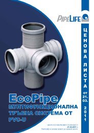
3. Product range3.1. <strong>PROFOS</strong> Identification descriptionAn example:<strong>PROFOS</strong>-PRO1000-5-D-AC-SE1.80.80.40Modular sewage pump stationManhole type and diameter in mm:PRO630PRO800PRO1000PRAGNUM1500PRAGNUM2000Depth of laying in meters:1.522.533.544.555.5678910Number of pumps in Profos:S (single) – one pumpD (double)- two pumpsPumps assembly:АC – auto-coupling systemFS – free-standingPump type:АPGDPSEGSE1SL1SEVSLVPump model:max. free passage of pump / Solid particles maximal size [mm](N/A for pumps APG and SEG )Supercharge outlet /supercharge outlet nominal diameter [mm]Power / Engine’s Output power P2/100 [W]<strong>Pipelife</strong>www.pipelife.com5
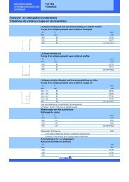
Pump productcodePump type/modelRatedCapacity Pressure Nominal current Velocitycurrentl/s m m/sDimensions withautocoupling system, mmNominal Nominal Nominal, kW А (ampere) Max. L B H1 96002612 APG.50.18.1x230V -external thread 2" 2,91 19,10 1,8 11,5 1,48 405* 410* 265*2 96002623 APG.50.19.3x400V -external thread 2" 2,78 20,90 1,9 4,4 1,41 405* 410* 265*3 96005343 APG.50.65.3x400V-flange 4,23 42,20 6,5 13,4 2,16 729 290 3004 96005345 APG.50.92.3x400V -flange 4,03 57,90 9,2 19,1 2,05 729 290 3005 96104200 DP10.50.09.2.1.502-internal thread 2" 5,54 8,68 0,9 6,1 2,82 307* 227* 141*6 96104204 DP10.50.09.2.50B-internal thread 2" 5,29 8,95 0,9 2,8 2,69 307* 227* 141*7 96104202 DP10.50.09.A.2.1.502-internal thread 2" 5,54 8,68 0,9 6,1 2,82 307* 227* 141*8 96104206 DP10.50.09.A.2.50B-internal thread 2" 5,29 8,95 0,9 2,8 2,69 307* 227* 141*9 96104208 DP10.50.15.2.50B-internal thread 2" 6,22 14,00 1,5 3,8 3,17 307* 227* 141*10 96104210 DP10.50.15.A.2.50B-internal thread 2" 6,22 14,00 1,5 3,8 3,17 307* 227* 141*11 96106542 DP10.65.26.2.50B-flange 5,86 20,80 2,6 5,8 1,77 630 252 26612 96106544 DP10.65.26.A.2.50B-flange 5,86 20,80 2,6 5,8 1,77 630 252 26613 96075893 SEG.40.09.2.1.502-internal thread 11/2" 1,97 8,74 0,9 6,2 1,57 424 214 22114 96075897 SEG.40.09.2.50B-internal thread 11/2" 2,11 8,89 0,9 2,7 1,68 424 214 22115 96075901 SEG.40.12.2.1.502-internal thread 11/2" 2,26 14,30 1,2 8,2 1,80 424 214 22116 96075905 SEG.40.12.2.50B-internal thread 11/2" 2,26 14,90 1,2 3,2 1,80 424 214 22117 96075909 SEG.40.15.2.50B-internal thread 11/2" 2,28 20,10 1,5 3,8 1,81 424 214 22118 96075913 SEG.40.26.2.50B-internal thread 11/2" 2,28 26,90 2,6 6,1 1,82 460 254 22119 96075915 SEG.40.31.2.50B-internal thread 11/2" 2,29 30,90 3,1 6,3 1,82 460 254 22120 96075917 SEG.40.40.2.50B-internal thread 11/2" 2,29 40,30 4,0 8,2 1,82 460 254 22121 96047509 SE1.50.65.22.2.50D 9,26 11,50 2,2 5,1 2,79 700 321 26622 96047517 SE1.50.65.30.2.50D 10,60 15,10 3,0 6,8 3,19 700 321 26623 96047525 SE1.50.65.40.2.51D 11,16 19,10 4,0 8,7 3,51 741 379 26624 96047981 SE1.50.80.22.2.50D 11,40 10,30 2,2 5,1 2,26 719 321 34525 96047989 SE1.50.80.30.2.50D 13,00 13,50 3,0 6,8 2,58 719 321 34526 96047997 SE1.50.80.40.2.51D 13,20 18,10 4,0 8,7 2,63 760 379 34527 96048005 SE1.80.100.15.4.50D 15,90 5,42 1,5 4,2 - 878 347 41328 96048021 SE1.80.100.22.4.50D 17,90 7,83 2,2 6,0 - 878 347 41329 96048037 SE1.80.100.30.4.50D 21,20 8,24 3,0 8,0 - 948 397 41330 96048069 SE1.80.100.40.4.51D 24,30 9,58 4,0 10,2 - 948 397 41331 96048085 SE1.80.100.55.4.51D 26,50 12,80 5,5 13,8 - 948 397 41332 96048099 SE1.80.100.75.4.51D 30,20 15,20 7,5 17,7 - 972 423 41333 96047533 SE1.80.80.15.4.50D 9,52 6,63 1,5 4,2 1,89 788 347 34534 96047549 SE1.80.80.22.4.50D 12,40 9,28 2,2 6,0 2,47 788 347 34535 96047565 SE1.80.80.30.4.50D 14,80 9,60 3,0 8,0 2,95 858 397 34536 96047597 SE1.80.80.40.4.51D 17,90 11,10 4,0 10,2 3,55 858 397 34537 96047613 SE1.80.80.55.4.51D 18,50 14,70 5,5 13,8 3,68 858 397 34538 96047627 SE1.80.80.75.4.51D 21,40 17,30 7,5 17,7 4,26 883 423 34539 96177642 SE1.80.100.22.A.4.50D 17,90 7,83 2,2 6,0 - 878 347 41340 96177644 SE1.80.100.40.A.4.51D 24,30 9,58 4,0 10,2 - 948 397 41341 96047641 SE1.100.100.40.4.51D 25,80 8,48 4,0 10,0 3,28 983 438 41342 96047657 SE1.100.100.55.4.51D 26,15 11,10 5,5 13,8 3,37 983 438 41343 96047671 SE1.100.100.75.4.51D 26,50 14,80 7,5 17,7 3,37 983 462 41344 96177649 SE1.100.100.75.A.4.51D 26,50 14,80 7,5 17,7 3,37 983 462 41345 96048113 SE1.100.150.40.4.51D 32,40 7,60 4,0 10,2 1,83 1093 440 45046 96048129 SE1.100.150.55.4.51D 37,00 9,23 5,5 13,8 2,10 1093 440 45047 96177651 SE1.100.150.55.A.4.51D 37,00 9,23 5,5 13,8 2,10 1093 440 45048 96048143 SE1.100.150.75.4.51D 41,70 11,70 7,5 17,7 2,36 1093 472 45049 96106562 SL1.50.65.09.2.1.502 7,71 5,49 0,9 6,1 2,32 671 242 26650 96106564 SL1.50.65.09.A.2.1.502 7,71 5,49 0,9 6,1 2,32 671 242 26651 96106566 SL1.50.65.09.2.50B 7,64 5,44 0,9 2,8 2,30 671 242 26652 96106570 SL1.50.65.09.A.2.50B 7,64 5,44 0,9 2,8 2,30 671 242 26653 96104125 SL1.50.65.11.2.1.502 8,50 6,94 1,1 7,4 2,56 671 242 26654 96104127 SL1.50.65.11.A.2.1.502 8,50 6,94 1,1 7,4 2,56 671 242 26655 96104129 SL1.50.65.11.2.50B 8,45 6,97 1,1 3,1 2,55 671 242 26656 96104133 SL1.50.65.11.A.2.50B 8,45 6,97 1,1 3,1 2,55 671 242 26657 96104118 SL1.50.65.15.2.50B 9,29 8,12 1,5 3,8 2,80 671 242 26658 96104122 SL1.50.65.15.A.2.50B 9,29 8,12 1,5 3,8 2,80 671 242 26659 96836307 SL1.50.65.22.2.50D 9,26 11,50 2,2 4,9 2,79 700 321 26660 96871937 SL1.50.65.22.A.2.50D 9,26 11,50 2,2 4,9 2,79 700 321 26661 96836311 SL1.50.65.30.2.50D 10,60 15,10 3,0 6,8 3,19 700 321 26662 96871940 SL1.50.65.30.A.2.50D 10,60 15,10 3,0 6,8 3,19 700 321 26663 96872032 SL1.50.65.40.2.51D 11,60 19,10 4,0 8,5 3,51 741 379 26664 96872034 SL1.50.65.40.A.2.51D 11,60 19,10 4,0 8,5 3,51 741 379 26665 96836286 SL1.50.80.22.2.50D 11,40 10,30 2,2 4,9 2,26 719 321 34566 96871952 SL1.50.80.22.A.2.50D 11,40 10,30 2,2 4,9 2,26 719 321 34567 96836289 SL1.50.80.30.2.50D 13,00 13,50 3,0 6,8 2,58 719 321 345<strong>Pipelife</strong>www.pipelife.com68 96871953 SL1.50.80.30.A.2.50D 13,00 13,50 3,0 6,8 2,58 719 321 34569 96872071 SL1.50.80.40.2.51D 13,20 18,10 4,0 8,5 2,63 760 379 34570 96872102 SL1.50.80.40.A.2.51D 13,20 18,10 4,0 8,5 2,63 760 379 34571 96872130 SL1.80.80.15.4.50D 9,52 6,63 1,5 3,9 1,89 788 347 345672 96872143 SL1.80.80.15.A.4.50D 9,52 6,63 1,5 3,9 1,89 788 347 34573 96836605 SL1.80.80.22.4.50D 12,40 9,28 2,2 5,3 2,47 788 347 345
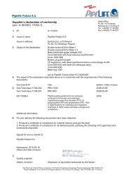
DN/ODdischarging pipemmManhole type/number of pumps in itPRO PIPPELIFEDN630 DN800 DN1000PRO PRAGNUMAuto-couplingsystemAssembly typeFree-standing50 1 1 2 2 • •50 1 1 2 2 •65 - - 2 265 - - 2 2••50 1 2 2 2 • •50 1 2 2 2 • •50 1 2 2 2 • •50 1 2 2 2 • •50 1 2 2 2 • •50 1 2 2 2 • •75 - 1 2 275 - 1 2 2••50 1 2 2 2 • • (base stand)50 1 2 2 2 • • (base stand)50 1 2 2 2 • • (base stand)50 1 2 2 2 • • (base stand)50 1 2 2 2 • • (base stand)50 1 2 2 2 • • (base stand)50 1 2 2 2 • • (base stand)50 1 2 2 2 • • (base stand)75 - - 2 2 • • (RS)75 - - 2 2 • • (RS)75 - - 2 2 • • (RS)90 - - 2 2 • • (RS)90 - - 2 2 • • (RS)90 - - 1 2 • • (RS)110 - - 1 2 • • (RS)110 - - 1 2 • • (RS)110 - - 1 2 • • (RS)110 - - 1 2 • • (RS)110 - - 1 2 • • (RS)110 - - 1 2 • • (RS)90 - - 1 2 • • (RS)90 - - 1 2 • • (RS)90 - - - 2 • • (RS)90 - - - 2 • • (RS)90 - - - 2 • • (RS)90 - - - 2 • • (RS)110 - - - 2 • • (RS)110 - - - 2 • • (RS)110 - - - 2 • • (RS)110 - - - 2 • • (RS)110 - - - 2 • • (RS)110 - - - 2 • • (RS)160 - - - 2 • • (RS)160 - - - 2 • • (RS)160 - - - 2160 - - - 2••• (RS)• (RS)PortableApplicationWater contaminated with sand, mud and admixtures,underground waters, faecal water from restaurants, hotels,camping sites etc., pressure sewage for pipeline waters withsmall capacity and big pressure.Drainage and underground waters.Rain waters.Waters from industry processes without solid particles andfibres.Waste waters from toilets, restaurants, hotels, campingsites etc.Not appropriate for drainage and underground waters.Waste waters, high quantities drainage and undergroundwaters, industry waters and untreated “raw” water inWWTP and other industry applications.Waste waters with dissolved gasses and high concentrationof fibres75 - 1 2 2 • • (RS)75 - 1 2 2 • • (RS)75 - 1 2 2 • • (RS)75 - 1 2 2 • • (RS)75 - 1 2 2 • • (RS)75 - 1 2 2 • • (RS)75 - 1 2 2 • • (RS)75 - 1 2 2 • • (RS)75 - 1 2 2 • • (RS)75 - 1 2 2 • • (RS)75 - - 2 2 • • (RS)75 - - 2 2 • • (RS)75 - - 2 2 • • (RS)75 - - 2 2 • • (RS)75 - - 1 2 • • (RS)75 - - 1 2 • • (RS)90 - - 2 2 • • (RS)90 - - 2 2 • • (RS)90 - - 2 2 • • (RS)90 <strong>Pipelife</strong>- - 2 2 • • (RS)90 www.pipelife.com- - 1 2 • • (RS)90 - - 1 2 • • (RS)90 - - 1 2 • • (RS)90 - - 1 2 • • (RS)90 - - 1 2 • • (RS)Waste waters, high quantities drainage and undergroundwaters, industry waters and untreated “raw” water inWWTP and other industry applications.Waste waters with high concentration of fibres.7
55 96104129 SL1.50.65.11.2.50B 8,45 6,97 1,1 3,1 2,55 671 242 26656 96104133 SL1.50.65.11.A.2.50B 8,45 6,97 1,1 3,1 2,55 671 242 26657 96104118 SL1.50.65.15.2.50B 9,29 8,12 1,5 3,8 2,80 671 242 26658 96104122 SL1.50.65.15.A.2.50B 9,29 8,12 1,5 3,8 2,80 671 242 26659 96836307 SL1.50.65.22.2.50D 9,26 11,50 2,2 4,9 2,79 700 321 26660 96871937 SL1.50.65.22.A.2.50D 9,26 11,50 2,2 4,9 2,79 700 321 26661 96836311 SL1.50.65.30.2.50D 10,60 15,10Rated3,0 6,8 3,19 700Dimensions321with26662 Capacity Pressure VelocityPump96871940 SL1.50.65.30.A.2.50Dproduct10,60 15,10current3,0 Nominal 6,8current3,19 700autocoupling321system, mm26663 96872032 SL1.50.65.40.2.51D Pump type/modelcode11,60 l/s 19,10 m 4,0 8,5 3,51 m/s 741 379 26664 96872034 SL1.50.65.40.A.2.51D 11,60 19,10 4,0 8,5 3,51 741 379 266Nominal Nominal Nominal, kW А (ampere) Max. L B H65 96836286 SL1.50.80.22.2.50D 11,40 10,30 2,2 4,9 2,26 719 321 34566 1 96002612 96871952 APG.50.18.1x230V SL1.50.80.22.A.2.50D -external thread 2" 11,40 2,91 19,10 10,30 1,8 2,2 11,5 4,9 1,48 2,26 405* 719 410* 321 265* 34567 2 96002623 96836289 APG.50.19.3x400V SL1.50.80.30.2.50D-external thread 2" 13,00 2,78 20,90 13,50 1,9 3,0 4,4 6,8 1,41 2,58 405* 719 410* 321 265* 34568 3 96005343 96871953 APG.50.65.3x400V-flange SL1.50.80.30.A.2.50D 13,00 4,23 42,20 13,50 6,5 3,0 13,4 6,8 2,16 2,58 729 719 290 321 300 34569 4 96005345 96872071 APG.50.92.3x400V SL1.50.80.40.2.51D-flange 13,20 4,03 57,90 18,10 9,2 4,0 19,1 8,5 2,05 2,63 729 760 290 379 300 34570 96872102 SL1.50.80.40.A.2.51D 13,20 18,10 4,0 8,5 2,63 760 379 34571 5 96104200 96872130 DP10.50.09.2.1.502-internal SL1.80.80.15.4.50D thread 2" 5,54 9,52 8,68 6,63 0,9 1,5 6,1 3,9 2,82 1,89 307* 788 227* 347 141* 34572 6 96104204 96872143 DP10.50.09.2.50B-internal SL1.80.80.15.A.4.50D thread 2" 5,29 9,52 8,95 6,63 0,9 1,5 2,8 3,9 2,69 1,89 307* 788 227* 347 141* 34573 7 96104202 96836605 DP10.50.09.A.2.1.502-internal SL1.80.80.22.4.50D thread 2" 12,40 5,54 9,28 8,68 2,2 0,9 5,3 6,1 2,47 2,82 307* 788 227* 347 141* 34574 8 96104206 96837225 DP10.50.09.A.2.50B-internal SL1.80.80.22.A.4.50D thread 2" 12,40 5,29 9,28 8,95 2,2 0,9 5,3 2,8 2,47 2,69 307* 788 227* 347 141* 34575 9 96104208 96872177 DP10.50.15.2.50B-internal SL1.80.80.30.4.50D thread 2" 14,80 6,22 14,00 9,60 3,0 1,5 7,2 3,8 2,95 3,17 307* 858 227* 397 141* 34510 76 96104210 96872179 DP10.50.15.A.2.50B-internal SL1.80.80.30.A.4.50D thread 2" 14,80 6,22 14,00 9,60 3,0 1,5 7,2 3,8 2,95 3,17 307* 858 227* 397 141* 34511 77 96106542 96872217 DP10.65.26.2.50B-flange SL1.80.80.40.4.51D 17,90 5,86 11,10 20,80 4,0 2,6 9,7 5,8 3,55 1,77 858 630 397 252 345 26612 78 96106544 96872218 DP10.65.26.A.2.50B-flange SL1.80.80.40.A.4.51D 17,90 5,86 11,10 20,80 4,0 2,6 9,7 5,8 3,55 1,77 858 630 397 252 345 26679 96873771 SL1.80.80.55.4.51D 18,50 14,70 5,5 11,8 3,68 858 397 34513 80 96075893 96872255 SEG.40.09.2.1.502-internal SL1.80.80.55.A.4.51D thread 11/2" 18,50 1,97 14,70 8,74 5,5 0,9 11,8 6,2 3,68 1,57 858 424 397 214 345 22114 81 96075897 96873359 SEG.40.09.2.50B-internal SL1.80.80.75.4.51D thread 11/2" 21,40 2,11 17,30 8,89 7,5 0,9 15,2 2,7 4,26 1,68 883 424 423 214 345 22115 82 96075901 96873372 SEG.40.12.2.1.502-internal SL1.80.80.75.A.4.51D thread 11/2" 21,40 2,26 17,30 14,30 7,5 1,2 15,2 8,2 4,26 1,80 883 424 423 214 345 22116 83 96075905 96836267 SEG.40.12.2.50B-internal SL1.80.100.15.4.50D thread 11/2" 15,90 2,26 14,90 5,42 1,5 1,2 3,9 3,2 2,02 1,80 878 424 347 214 413 22117 84 96075909 96871954 SEG.40.15.2.50B-internal SL1.80.100.15.A.4.50D thread 11/2" 15,90 2,28 20,10 5,42 1,5 3,9 3,8 2,02 1,81 878 424 347 214 413 22118 85 96075913 96836271 SEG.40.26.2.50B-internal SL1.80.100.22.4.50D thread 11/2" 17,90 2,28 26,90 7,83 2,2 2,6 5,3 6,1 2,27 1,82 878 460 347 254 413 22119 86 96075915 96871955 SEG.40.31.2.50B-internal SL1.80.100.22.A.4.50D thread 11/2" 17,90 2,29 30,90 7,83 2,2 3,1 5,3 6,3 2,27 1,82 878 460 347 254 413 22120 87 96075917 96836283 SEG.40.40.2.50B-internal SL1.80.100.30.4.50D thread 11/2" 21,20 2,29 40,30 8,24 3,0 4,0 7,2 8,2 2,69 1,82 948 460 397 254 413 22188 96871956 SL1.80.100.30.A.4.50D 21,20 8,24 3,0 7,2 2,69 948 397 41321 89 96047509 96873358 SE1.50.65.22.2.50D SL1.80.100.40.4.51D 24,30 9,26 11,50 9,58 4,0 2,2 9,7 5,1 3,10 2,79 948 700 397 321 413 26622 90 96047517 96873375 SE1.50.65.30.2.50D SL1.80.100.40.A.4.51D 10,60 24,30 15,10 9,58 3,0 4,0 6,8 9,7 3,19 3,10 700 948 321 397 266 41323 91 96047525 96873360 SE1.50.65.40.2.51D SL1.80.100.55.4.51D 11,16 26,50 19,10 12,80 4,0 5,5 11,8 8,7 3,51 3,37 741 948 379 397 266 41324 92 96047981 96873376 SE1.50.80.22.2.50D SL1.80.100.55.A.4.51D 11,40 26,50 10,30 12,80 2,2 5,5 11,8 5,1 2,26 3,37 719 948 321 397 345 41325 93 96047989 96873361 SE1.50.80.30.2.50D SL1.80.100.75.4.51D 13,00 30,20 13,50 15,20 3,0 7,5 15,2 6,8 2,58 3,84 719 972 321 423 345 41326 94 96047997 96873377 SE1.50.80.40.2.51D SL1.80.100.75.A.4.51D 13,20 30,20 18,10 15,20 4,0 7,5 15,2 8,7 2,63 3,84 760 972 379 423 345 41327 95 96048005 96873364 SE1.80.100.15.4.50D SL1.100.100.40.4.51D 15,90 25,80 5,42 8,48 1,5 4,0 4,2 9,7 3,28 - 878 983 347 438 41328 96 96048021 96873380 SE1.80.100.22.4.50D SL1.100.100.40.A.4.51D 17,90 25,80 7,83 8,48 2,2 4,0 6,0 9,7 3,28 - 878 983 347 438 41329 97 96048037 96873365 SE1.80.100.30.4.50D SL1.100.100.55.4.51D 21,20 26,50 11,10 8,24 3,0 5,5 11,8 8,0 3,37 - 948 983 397 438 41330 98 96048069 96873381 SE1.80.100.40.4.51D SL1.100.100.55.A.4.51D 24,30 26,50 11,10 9,58 4,0 5,5 10,2 11,8 3,37 - 948 983 397 438 41331 99 96048085 96873366 SE1.80.100.55.4.51D SL1.100.100.75.4.51D 26,50 12,80 14,80 5,5 7,5 15,2 13,8 3,37 - 948 983 397 462 413100 32 96048099 96873382 SE1.80.100.75.4.51D SL1.100.100.75.A.4.51D 30,20 26,50 15,20 14,80 7,5 17,7 15,2 3,37 - 972 983 423 462 413101 33 96047533 96873367 SE1.80.80.15.4.50D SL1.100.150.40.4.51D 32,40 9,52 7,60 6,63 4,0 1,5 9,7 4,2 1,83 1,89 1093 788 440 347 450 345102 34 96047549 96873383 SE1.80.80.22.4.50D SL1.100.150.40.A.4.51D 12,40 32,40 9,28 7,60 2,2 4,0 6,0 9,7 2,47 1,83 1093 788 440 347 450 345103 35 96873368 96047565 SE1.80.80.30.4.50D SL1.100.150.55.4.51D 14,80 37,00 9,60 9,23 3,0 5,5 11,8 8,0 2,95 2,10 1093 858 397 440 345 450104 36 96047597 96873384 SE1.80.80.40.4.51D SL1.100.150.55.A.4.51D 17,90 37,00 11,10 9,23 4,0 5,5 10,2 11,8 3,55 2,10 1093 858 440 397 450 345105 37 96047613 96873369 SE1.80.80.55.4.51D SL1.100.150.75.4.51D 18,50 41,70 14,70 11,70 5,5 7,5 13,8 15,2 3,68 2,36 1093 858 472 397 450 345106 38 96047627 96873385 SE1.80.80.75.4.51D SL1.100.150.75.A.4.51D 21,40 41,70 17,30 11,70 7,5 17,7 15,2 4,26 2,36 1093 883 472 423 450 34539 96177642 SE1.80.100.22.A.4.50D 17,90 7,83 2,2 6,0 - 878 347 413107 40 96177644 96047697 SE1.80.100.40.A.4.51D SEV.65.65.22.2.50D 24,30 5,95 11,20 9,58 4,0 2,2 10,2 5,1 1,79 - 948 730 397 321 413 266108 41 96047641 96047713 SE1.100.100.40.4.51D SEV.65.65.30.2.50D 25,80 5,95 15,10 8,48 4,0 3,0 10,0 6,8 3,28 1,79 983 730 438 321 413 266109 42 96047657 96047729 SE1.100.100.55.4.51D SEV.65.65.40.2.51D 26,15 7,94 11,10 18,50 5,5 4,0 13,8 8,7 3,37 2,39 983 790 438 380 413 266110 43 96047671 96048169 SE1.100.100.75.4.51D SEV.65.80.22.2.50D 26,50 5,95 14,80 11,30 7,5 2,2 17,7 5,1 3,37 1,18 983 750 462 321 413 345111 44 96177649 96048185 SE1.100.100.75.A.4.51D SEV.65.80.30.2.50D 26,50 5,95 14,80 15,10 7,5 3,0 17,7 6,8 3,37 1,18 983 750 462 321 413 345112 45 96048113 96048201 SE1.100.150.40.4.51D SEV.65.80.40.2.51D 32,40 7,94 19,10 7,60 4,0 10,2 8,7 1,83 1,58 1093 808 440 379 450 345113 46 96048129 96047745 SE1.100.150.55.4.51D SEV.80.80.11.4.50D 37,00 7,67 9,23 4,83 5,5 1,1 13,8 2,9 2,10 1,53 1093 762 440 339 450 345114 47 96177651 96047877 SE1.100.150.55.A.4.51D SEV.80.80.110.2.51D 37,00 11,90 35,50 9,23 11,0 5,5 13,8 22,7 2,10 2,37 1093 842 440 413 450 345115 48 96048143 96047757 SE1.100.150.75.4.51D SEV.80.80.13.4.50D 41,70 8,60 11,70 6,11 7,5 1,3 17,7 3,9 2,36 1,71 1093 762 472 339 450 345116 96047769 SEV.80.80.15.4.50D 9,52 6,98 1,5 4,2 1,89 762 339 345117 49 96106562 96047781 SL1.50.65.09.2.1.502 SEV.80.80.22.4.50D 11,10 7,71 9,13 5,49 2,2 0,9 6,0 6,1 2,21 2,32 762 671 339 242 345 266118 50 96106564 96047829 SL1.50.65.09.A.2.1.502 SEV.80.80.40.2.51D 10,60 7,71 12,30 5,49 4,0 0,9 8,7 6,1 2,11 2,32 809 671 380 242 345 266119 51 96106566 96047797 SL1.50.65.09.2.50B SEV.80.80.40.4.51D 11,90 7,64 13,20 5,44 4,0 0,9 10,2 2,8 2,37 2,30 813 671 393 242 345 266120 52 96106570 96047845 SL1.50.65.09.A.2.50B SEV.80.80.60.2.51D 11,90 7,64 16,30 5,44 6,0 0,9 14,2 2,8 2,37 2,30 809 671 380 242 345 266121 53 96104125 96047861 SL1.50.65.11.2.1.502 SEV.80.80.75.2.51D 11,90 8,50 24,00 6,94 7,5 1,1 18,8 7,4 2,37 2,56 809 671 380 242 345 266122 54 96104127 96047207 SL1.50.65.11.A.2.1.502 SEV.80.80.92.2.51D 11,90 8,50 28,20 6,94 9,2 1,1 18,8 7,4 2,37 2,56 842 671 413 242 345 266123 55 96104129 96177660 SL1.50.65.11.2.50B SEV.80.80.13.A.4.50D 8,45 8,60 6,97 6,11 1,1 1,3 3,1 3,9 2,55 1,71 671 762 242 339 266 345124 56 96104133 96177661 SL1.50.65.11.A.2.50B SEV.80.80.15.A.4.50D 8,45 9,52 6,97 6,98 1,1 1,5 3,1 4,2 2,55 1,89 671 762 242 339 266 345125 57 96104118 96177663 SL1.50.65.15.2.50B SEV.80.80.40.A.4.51D 11,10 9,29 9,13 8,12 2,2 1,5 10,2 3,8 2,21 2,80 762 671 339 242 345 266126 58 96104122 96177665 SL1.50.65.15.A.2.50B SEV.80.80.60.A.2.51D 11,90 9,29 16,30 8,12 6,0 1,5 14,2 3,8 2,37 2,80 809 671 380 242 345 266127 59 96836307 96177666 SL1.50.65.22.2.50D SEV.80.80.75.A.2.51D 11,90 9,26 24,00 11,50 7,5 2,2 16,5 4,9 2,37 2,79 809 700 380 321 345 266128 60 96871937 96177667 SL1.50.65.22.A.2.50D SEV.80.80.92.A.2.51D 11,90 9,26 28,20 11,50 9,2 2,2 18,8 4,9 2,37 2,79 842 700 413 321 345 266129 61 96836311 96177662 SL1.50.65.30.2.50D SEV.80.80.22.A.4.50D 10,60 11,10 15,10 9,13 3,0 2,2 6,8 5,9 3,19 2,21 700 762 321 339 266 345130 62 96871940 96047893 SL1.50.65.30.A.2.50D SEV.100.100.30.4.50D 10,60 15,20 15,10 6,75 3,0 6,8 8,0 3,19 1,94 700 900 321 380 266 413131 63 96872032 96047925 SL1.50.65.40.2.51D SEV.100.100.40.4.51D 11,60 16,50 19,10 9,33 4,0 10,2 8,5 3,51 2,11 741 900 379 380 266 413132 64 96872034 96047941 SL1.50.65.40.A.2.51D SEV.100.100.55.4.51D 11,60 17,90 19,10 12,40 4,0 5,5 13,8 8,5 3,51 2,27 741 900 379 380 266 413133 65 96836286 96047957 SL1.50.80.22.2.50D SEV.100.100.75.4.51D 11,40 19,20 10,30 16,00 2,2 7,5 17,7 4,9 2,26 2,44 719 933 321 413 345 413134 66 96871952 96177669 SL1.50.80.22.A.2.50D SEV.100.100.30.A.4.50D 11,40 15,20 10,30 6,75 2,2 3,0 4,9 8,0 2,26 1,94 719 900 321 380 345 413135 67 96836289 96177671 SL1.50.80.30.2.50D SEV.100.100.55.A.4.51D 13,00 17,90 13,50 12,40 3,0 5,5 13,8 6,8 2,58 2,27 719 900 321 380 345 41368 96871953 SL1.50.80.30.A.2.50D 13,00 13,50 3,0 6,8 2,58 719 321 <strong>Pipelife</strong>345136 69 96872071 96115119 SL1.50.80.40.2.51D SLV.65.65.09.2.1.502 13,20 4,90 18,10 3,09 4,0 0,9 8,5 6,1 2,63 1,48 760 671 www.pipelife.com379 242 345 266137 70 96872102 96115121 SL1.50.80.40.A.2.51D SLV.65.65.09.A.2.1.502 13,20 4,90 18,10 3,09 4,0 0,9 8,5 6,1 2,63 1,48 760 671 379 242 345 266138 71 96872130 96115123 SL1.80.80.15.4.50D SLV.65.65.09.2.50B 9,52 4,90 6,63 3,11 1,5 0,9 3,9 2,8 1,89 1,48 788 671 347 242 345 2668139 72 96872143 96115125 SL1.80.80.15.A.4.50D SLV.65.65.09.A.2.50B 9,52 4,90 6,63 3,11 1,5 0,9 3,9 2,8 1,89 1,48 788 671 347 242 345 26673 96836605 SL1.80.80.22.4.50D 12,40 9,28 2,2 5,3 2,47 788 347 345
7575--112222••• (RS)• (RS)75 - 1 2 2 • • (RS)75 - 1 2 2 • • (RS)75 - - 2 2 • • (RS)75 - - 2 2 • • (RS)75 -Manhole-type/number2of pumps in2it•Assembly• (RS)typeDN/OD 75 - - 2 2 • • (RS)75 - PRO PIPPELIFE - 1 2 • • (RS)mmAuto-coupling Free-standing75 - - 1 PRO PRAGNUM 2 • • (RS)DN630 DN800 DN1000system90 - - 2 2 • • (RS)50 90 1- 1- 2 2 • • (RS) • •50 90 1- 1- 2 2 • • (RS) •65 90 - - 2 2 • • (RS)65 90 - - 21 2 • • (RS)90 - - 1 2 • • (RS)90 50 1- 2- 21 2 • • (RS) • •50 90 1- 2- 21 2 • • (RS) • •50 90 1- 2- 21 2 • • (RS) • •90 50 1- 2- 21 2 • • (RS) • •50 90 1- 2- 2- 2 • • (RS) • •50 90 1- 2- 2- 2 • • (RS) • •90 75 - 1- 2- 2 • • (RS)90 75 - 1- 2- 2 • • (RS)90 - - - 2 • • (RS)90 50 1- 2- 2- 2 • • (base • (RS) stand)90 50 1- 2- 2- 2 • • (base • (RS) stand)90 50 1- 2- 2- 2 • • (base • (RS) stand)110 50 1- 2- 2- 2 • • (base • (RS) stand)110 50 1- 2- 2- 2 • • (base • (RS) stand)110 50 1- 2- 2- 2 • • (base • (RS) stand)110 50 1- 2- 2- 2 • • (base • (RS) stand)110 50 1- 2- 2- 2 • • (base • (RS) stand)110 - - - 2 • • (RS)110 75 - - 2- 2 • • (RS)110 75 - - 2- 2 • • (RS)110 75 - - 2- 2 • • (RS)110 90 - - 2- 2 • • (RS)110 90 - - 2- 2 • • (RS)110 90 - - 1- 2 • • (RS)110 - - 1- 2 • • (RS)110 - - 1- 2 • • (RS)110 - - 1- 2 • • (RS)110 - - 1- 2 • • (RS)110 - - 1- 2 • • (RS)110 - - 1- 2 • • (RS)160 90 - - 1- 2 • • (RS)160 90 - - 1- 2 • • (RS)160 90 - - - 2 • • (RS)160 90 - - - 2 • • (RS)160 90 - - - 2 • • (RS)160 90 - - - 2 • • (RS)110 - - - 2 • • (RS)110 75 - - 2- 2 • • (RS)110 75 - - 2- 2 • • (RS)110 75 - - 1- 2 • • (RS)110 90 - - 1- 2 • • (RS)110 90 - - 1- 2 • • (RS)160 90 - - 1- 2 • • (RS)160 90 - - 1- 2 • • (RS)160 90 - - 1- 2 • • (RS)160 90 - - 1- 2 • • (RS)90 - - 1 2 • • (RS)90 75 - 1- 12 2 • • (RS)90 75 - 1- 12 2 • • (RS)90 75 - 1- 12 2 • • (RS)90 75 - 1- 12 2 • • (RS)90 75 - 1- 12 2 • • (RS)90 75 - 1- 12 2 • • (RS)90 75 - 1- 12 2 • • (RS)75 90 - 1- 21 2 • • (RS)90 75 - 1- 12 2 • • (RS)90 75 - 1- 12 2 • • (RS)90 75 - - 12 2 • • (RS)90 75 - - 12 2 • • (RS)90 75 - - 12 2 • • (RS)110 75 - - 2- 2 • • (RS)110 75 - - 1- 2 • • (RS)110 75 - - 1- 2 • • (RS)110 90 - - 2- 2 • • (RS)110 90 - - 2- 2 • • (RS)110 90 - - 2- 2 • • (RS)90 <strong>Pipelife</strong>- - 2 2 • • (RS)90 75 www.pipelife.com- 1- 12 2 • • (RS)90 75 - 1- 21 2 • • (RS)90 75 - 1- 12 2 • • (RS)90 75 - 1- 12 2 • • (RS)90 - - 1 2 • • (RS)discharging pipePortableApplicationWaste waters, high quantities drainage and undergroundwaters, industry waters and untreated “raw” water inWWTP and other industry applications.Waste waters with high concentration of fibres.Waste waters, high quantities drainage and undergroundwaters, industry waters and untreated “raw” water inWWTP and other industry applications.Waste waters with dissolved gasses and high concentrationof fibres9
123 96177660 SEV.80.80.13.A.4.50D 8,60 6,11 1,3 3,9 1,71 762 339 345124 96177661 SEV.80.80.15.A.4.50D 9,52 6,98 1,5 4,2 1,89 762 339 345125 96177663 SEV.80.80.40.A.4.51D 11,10 9,13 2,2 10,2 2,21 762 339 345126 96177665 SEV.80.80.60.A.2.51D 11,90 16,30 6,0 14,2 2,37 809 380 345127 96177666 SEV.80.80.75.A.2.51D 11,90 24,00 7,5 16,5 2,37 809 380 345128 96177667 SEV.80.80.92.A.2.51D 11,90 28,20 9,2 18,8 2,37 842 413 345129 96177662 SEV.80.80.22.A.4.50D 11,10 9,13 2,2 5,9 2,21 762 339 345RatedDimensions with130 96047893 SEV.100.100.30.4.50D Capacity 15,20 Pressure 6,75 3,0 Nominal 8,0currentVelocity 1,94 900 380 413Pump productcurrentautocoupling system, mm131 96047925 SEV.100.100.40.4.51D Pump type/model16,50 9,33 4,0 10,2 2,11 900 380 413codel/s m m/s132 96047941 SEV.100.100.55.4.51D 17,90 12,40 5,5 13,8 2,27 900 380 413133 96047957NominalSEV.100.100.75.4.51D 19,20Nominal16,00Nominal,7,5kW А (ampere)17,7Max.2,44 933L413B413H134 1 96002612 96177669 SEV.100.100.30.A.4.50D APG.50.18.1x230V -external thread 2" 15,20 2,91 19,10 6,75 1,8 3,0 11,5 8,0 1,48 1,94 405* 900 410* 380 265* 413135 2 96002623 96177671 SEV.100.100.55.A.4.51D APG.50.19.3x400V -external thread 2" 17,90 2,78 20,90 12,40 1,9 5,5 13,8 4,4 1,41 2,27 405* 900 410* 380 265* 4133 96005343 APG.50.65.3x400V-flange 4,23 42,20 6,5 13,4 2,16 729 290 300136 4 96005345 96115119 SLV.65.65.09.2.1.502 APG.50.92.3x400V -flange 4,03 4,90 57,90 3,09 9,2 0,9 19,1 6,1 2,05 1,48 729 671 290 242 300 266137 96115121 SLV.65.65.09.A.2.1.502 4,90 3,09 0,9 6,1 1,48 671 242 266138 5 96104200 96115123 SLV.65.65.09.2.50B DP10.50.09.2.1.502-internal thread 2" 4,90 5,54 3,11 8,68 0,9 2,8 6,1 1,48 2,82 307* 671 227* 242 141* 266139 6 96104204 96115125 SLV.65.65.09.A.2.50B DP10.50.09.2.50B-internal thread 2" 4,90 5,29 3,11 8,95 0,9 2,8 1,48 2,69 307* 671 227* 242 141* 266140 7 96104202 96106573 SLV.65.65.11.2.1.502 DP10.50.09.A.2.1.502-internal thread 2" 5,64 5,54 4,27 8,68 1,1 0,9 7,4 6,1 1,70 2,82 307* 671 227* 242 141* 266141 8 96104206 96106575 SLV.65.65.11.A.2.1.502 DP10.50.09.A.2.50B-internal thread 2" 5,64 5,29 4,27 8,95 1,1 0,9 7,4 2,8 1,70 2,69 307* 671 227* 242 141* 266142 9 96104208 96106577 SLV.65.65.11.2.50B DP10.50.15.2.50B-internal thread 2" 5,64 6,22 14,00 4,35 1,1 1,5 3,1 3,8 1,70 3,17 307* 671 227* 242 141* 266143 10 96104210 96106579 SLV.65.65.11.A.2.50B DP10.50.15.A.2.50B-internal thread 2" 5,64 6,22 14,00 4,35 1,1 1,5 3,1 3,8 1,70 3,17 307* 671 227* 242 141* 266144 11 96106542 96104192 SLV.65.65.15.2.50B DP10.65.26.2.50B-flange 5,95 5,86 20,80 4,94 1,5 2,6 3,8 5,8 1,79 1,77 671 630 242 252 266145 12 96106544 96104194 SLV.65.65.15.A.2.50B DP10.65.26.A.2.50B-flange 5,95 5,86 20,80 4,94 1,5 2,6 3,8 5,8 1,79 1,77 671 630 242 252 266146 96836323 SLV.65.65.22.2.50D 5,95 11,20 2,2 4,9 1,79 730 321 266147 13 96075893 96871926 SLV.65.65.22.A.2.50D SEG.40.09.2.1.502-internal thread 11/2" 5,95 1,97 11,20 8,74 0,9 2,2 6,2 4,9 1,57 1,79 424 730 321 214 266 221148 96075897 96871968 SLV.65.65.30.2.50D SEG.40.09.2.50B-internal thread 11/2" 5,95 2,11 15,10 8,89 0,9 3,0 2,7 6,8 1,68 1,79 424 730 321 214 266 221149 15 96075901 96872135 SLV.65.65.30.A.2.50D SEG.40.12.2.1.502-internal thread 11/2" 5,95 2,26 15,10 14,30 3,0 1,2 6,8 8,2 1,79 1,80 730 424 321 214 266 221150 16 96075905 96871971 SLV.65.65.40.2.51D SEG.40.12.2.50B-internal thread 11/2" 7,94 2,26 18,50 14,90 4,0 1,2 8,5 3,2 2,39 1,80 790 424 380 214 266 221151 17 96075909 96872137 SLV.65.65.40.A.2.51D SEG.40.15.2.50B-internal thread 11/2" 7,94 2,28 18,50 20,10 4,0 1,5 8,5 3,8 2,39 1,81 790 424 380 214 266 221152 18 96075913 96836287 SLV.65.80.22.2.50D SEG.40.26.2.50B-internal thread 11/2" 5,95 2,28 11,30 26,90 2,2 2,6 4,9 6,1 1,18 1,82 750 460 321 254 345 221153 19 96075915 96871930 SLV.65.80.22.A.2.50D SEG.40.31.2.50B-internal thread 11/2" 5,95 2,29 11,30 30,90 2,2 3,1 4,9 6,3 1,18 1,82 750 460 321 254 345 221154 20 96075917 96836303 SLV.65.80.30.2.50D SEG.40.40.2.50B-internal thread 11/2" 5,95 2,29 15,10 40,30 3,0 4,0 6,8 8,2 1,18 1,82 750 460 321 254 345 221155 96871931 SLV.65.80.30.A.2.50D 5,95 15,10 3,0 6,8 1,18 750 321 345156 21 96047509 96842221 SLV.65.80.40.2.51D SE1.50.65.22.2.50D 7,94 9,26 19,10 11,50 4,0 2,2 8,5 5,1 1,58 2,79 808 700 379 321 345 266157 22 96047517 96872152 SLV.65.80.40.A.2.51D SE1.50.65.30.2.50D 10,60 7,94 15,10 19,10 3,0 4,0 6,8 8,5 3,19 1,58 700 808 321 379 266 345158 23 96047525 96836266 SLV.80.80.11.4.50D SE1.50.65.40.2.51D 11,16 7,67 19,10 4,83 4,0 1,1 8,7 3,0 3,51 1,53 741 762 379 339 266 345159 24 96047981 96837216 SLV.80.80.11.A.4.50D SE1.50.80.22.2.50D 11,40 7,67 10,30 4,83 2,2 1,1 5,1 3,0 2,26 1,53 719 762 321 339 345160 25 96047989 96857830 SLV.80.80.13.4.50D SE1.50.80.30.2.50D 13,00 8,60 13,50 6,11 3,0 1,7 6,8 3,6 2,58 1,71 719 762 321 339 345161 26 96047997 96871962 SLV.80.80.13.A.4.50D SE1.50.80.40.2.51D 13,20 8,60 18,10 6,11 4,0 1,7 8,7 3,6 2,63 1,71 760 762 379 339 345162 27 96048005 96836269 SLV.80.80.15.4.50D SE1.80.100.15.4.50D 15,90 9,52 5,42 6,98 1,5 4,2 3,9 1,89 - 878 762 347 339 413 345163 28 96048021 96871963 SLV.80.80.15.A.4.50D SE1.80.100.22.4.50D 17,90 9,52 7,83 6,98 2,2 1,5 6,0 3,9 1,89 - 878 762 347 339 413 345164 29 96048037 96835691 SLV.80.80.22.4.50D SE1.80.100.30.4.50D 11,10 21,20 9,13 8,24 2,2 3,0 5,3 8,0 2,21 - 948 762 397 339 413 345165 30 96048069 96835682 SLV.80.80.22.A.4.50D SE1.80.100.40.4.51D 11,10 24,30 9,13 9,58 2,2 4,0 10,2 5,3 2,21 - 948 762 397 339 413 345166 31 96048085 96871980 SLV.80.80.22.4.51D SE1.80.100.55.4.51D 11,10 26,50 12,80 9,13 2,2 5,5 13,8 5,3 2,21 - 948 762 339 397 345 413167 32 96048099 96872156 SLV.80.80.22.A.4.51D SE1.80.100.75.4.51D 11,10 30,20 15,20 9,13 2,2 7,5 17,7 5,3 2,21 - 972 762 423 339 413 345168 33 96047533 96871995 SLV.80.80.40.4.51D SE1.80.80.15.4.50D 11,90 9,52 13,20 6,63 4,0 1,5 9,7 4,2 2,37 1,89 813 788 339 347 345169 34 96047549 96872159 SLV.80.80.40.A.4.51D SE1.80.80.22.4.50D 11,90 12,40 13,20 9,28 4,0 2,2 9,7 6,0 2,37 2,47 813 788 339 347 345170 35 96047565 96871992 SLV.80.80.40.2.51D SE1.80.80.30.4.50D 10,60 14,80 12,30 9,60 4,0 3,0 8,5 8,0 2,11 2,95 809 858 380 397 345171 36 96047597 96872157 SLV.80.80.40.A.2.51D SE1.80.80.40.4.51D 10,60 17,90 12,30 11,10 4,0 10,2 8,5 2,11 3,55 809 858 380 397 345172 37 96047613 96873784 SLV.80.80.60.2.51D SE1.80.80.55.4.51D 11,90 18,50 16,30 14,70 6,0 5,5 12,5 13,8 2,37 3,68 809 858 380 397 345173 38 96047627 96872160 SLV.80.80.60.A.2.51D SE1.80.80.75.4.51D 11,90 21,40 16,30 17,30 6,0 7,5 12,5 17,7 2,37 4,26 809 883 380 423 345174 39 96871998 96177642 SLV.80.80.75.2.51D SE1.80.100.22.A.4.50D 11,90 17,90 24,00 7,83 7,5 2,2 15,1 6,0 2,37 - 878 809 347 380 413 345175 40 96177644 96872161 SLV.80.80.75.A.2.51D SE1.80.100.40.A.4.51D 11,90 24,30 24,00 9,58 7,5 4,0 15,1 10,2 2,37 - 948 809 397 380 413 345176 41 96047641 96872003 SLV.80.80.92.2.51D SE1.100.100.40.4.51D 11,90 25,80 28,20 8,48 9,2 4,0 18,0 10,0 2,37 3,28 842 983 413 438 345 413177 42 96047657 96872162 SLV.80.80.92.A.2.51D SE1.100.100.55.4.51D 11,90 26,15 28,20 11,10 9,2 5,5 18,0 13,8 2,37 3,37 842 983 413 438 345 413178 43 96047671 96872004 SLV.80.80.110.2.51D SE1.100.100.75.4.51D 11,90 26,50 35,50 14,80 11,0 7,5 17,7 21,4 3,37 2,37 983 842 462 413 413 345179 44 96177649 96872163 SLV.80.80.110.A.2.51D SE1.100.100.75.A.4.51D 11,90 26,50 35,50 14,80 11,0 7,5 17,7 21,4 3,37 2,37 983 842 462 413 413 345180 45 96048113 96872005 SLV.80.100.11.4.50D SE1.100.150.40.4.51D 32,40 7,80 7,60 4,91 4,0 1,1 10,2 3,0 1,83 0,99 1093 850 440 337 450 413181 46 96048129 96872165 SLV.80.100.11.A.4.50D SE1.100.150.55.4.51D 37,00 7,80 9,23 4,91 5,5 1,1 13,8 3,0 2,10 0,99 1093 850 440 337 450 413182 47 96177651 96890480 SLV.80.100.13.4.50D SE1.100.150.55.A.4.51D 37,00 8,37 9,23 6,04 5,5 1,3 13,8 3,6 2,10 1,11 1093 850 440 337 450 413183 48 96048143 96890782 SLV.80.100.13.A.4.50D SE1.100.150.75.4.51D 41,70 8,37 11,70 6,04 7,5 1,3 17,7 3,6 2,36 1,11 1093 850 472 337 450 413184 96872008 SLV.80.100.15.4.50D 9,66 7,10 1,5 3,9 1,23 850 337 413185 49 96106562 96872168 SLV.80.100.15.A.4.50D SL1.50.65.09.2.1.502 9,66 7,71 7,10 5,49 1,5 0,9 3,9 6,1 1,23 2,32 850 671 337 242 413 266186 50 96106564 96872244 SLV.80.100.22.4.50D SL1.50.65.09.A.2.1.502 11,20 7,71 9,08 5,49 2,2 0,9 5,3 6,1 1,43 2,32 850 671 337 242 413 266187 51 96106566 96872248 SLV.80.100.22.A.4.50D SL1.50.65.09.2.50B 11,20 7,64 9,08 5,44 2,2 0,9 5,3 2,8 1,43 2,30 850 671 337 242 413 266188 52 96106570 96872243 SLV.80.100.22.4.51D SL1.50.65.09.A.2.50B 11,20 7,64 9,08 5,44 2,2 0,9 5,3 2,8 1,43 2,30 850 671 337 242 413 266189 53 96104125 96872249 SLV.80.100.22.A.4.51D SL1.50.65.11.2.1.502 11,20 8,50 9,08 6,94 2,2 1,1 5,3 7,4 1,43 2,56 850 671 337 242 413 266190 54 96104127 96872022 SLV.80.100.40.4.51D SL1.50.65.11.A.2.1.502 11,90 8,50 13,50 6,94 4,0 1,1 9,7 7,4 1,52 2,56 901 671 391 242 413 266191 55 96104129 96872184 SLV.80.100.40.A.4.51D SL1.50.65.11.2.50B 11,90 8,45 13,50 6,97 4,0 1,1 9,7 3,1 1,52 2,55 901 671 391 242 413 266192 56 96104133 96872010 SLV.80.100.40.2.51D SL1.50.65.11.A.2.50B 11,90 8,45 13,50 6,97 4,0 1,1 8,5 3,1 1,52 2,55 909 671 380 242 413 266193 57 96104118 96872171 SLV.80.100.40.A.2.51D SL1.50.65.15.2.50B 11,90 9,29 13,50 8,12 4,0 1,5 8,5 3,8 1,52 2,80 909 671 380 242 413 266194 58 96104122 96893379 SLV.80.100.60.2.51D SL1.50.65.15.A.2.50B 12,70 9,29 15,40 8,12 6,0 1,5 12,5 3,8 1,62 2,80 909 671 380 242 413 266195 59 96836307 96872011 SLV.80.100.75.2.51D SL1.50.65.22.2.50D 14,60 9,26 19,40 11,50 7,5 2,2 15,1 4,9 1,85 2,79 909 700 380 321 413 266196 60 96871937 96872183 SLV.80.100.75.A.2.51D SL1.50.65.22.A.2.50D 14,60 9,26 19,40 11,50 7,5 2,2 15,1 4,9 1,85 2,79 909 700 380 321 413 266197 61 96836311 96872023 SLV.80.100.92.2.51D SL1.50.65.30.2.50D 15,90 10,60 22,70 15,10 9,2 3,0 18,0 6,8 2,02 3,19 942 700 413 321 413 266198 62 96871940 96872185 SLV.80.100.92.A.2.51D SL1.50.65.30.A.2.50D 15,90 10,60 22,70 15,10 9,2 3,0 18,0 6,8 2,02 3,19 942 700 413 321 413 266199 63 96872032 96890789 SLV.80.100.110.2.51D SL1.50.65.40.2.51D 17,20 11,60 27,80 19,10 11,0 4,0 21,4 8,5 3,51 2,19 741 942 379 413 266 413200 64 96872034 96890790 SLV.80.100.110.A.2.51D SL1.50.65.40.A.2.51D 17,20 11,60 27,80 19,10 11,0 4,0 21,4 8,5 3,51 2,19 741 942 379 413 266 413201 65 96836286 96836305 SLV.100.100.30.4.50D SL1.50.80.22.2.50D 15,20 11,40 10,30 6,75 3,0 2,2 7,2 4,9 1,94 2,26 900 719 380 321 413 345202 66 96871952 96871965 SLV.100.100.30.A.4.50D SL1.50.80.22.A.2.50D 15,20 11,40 10,30 6,75 3,0 2,2 7,2 4,9 1,94 2,26 900 719 380 321 413 345203 67 96836289 96872026 SLV.100.100.40.4.51D SL1.50.80.30.2.50D 16,50 13,00 13,50 9,33 4,0 3,0 9,7 6,8 2,11 2,58 900 719 380 321 413 345204 68 96871953 96872187 SLV.100.100.40.A.4.51D SL1.50.80.30.A.2.50D 16,50 13,00 13,50 9,33 4,0 3,0 9,7 6,8 2,11 2,58 900 719 380 321 <strong>Pipelife</strong>413345205 69 96872071 96872028 SLV.100.100.55.4.51D SL1.50.80.40.2.51D 17,90 13,20 12,40 18,10 5,5 4,0 11,8 8,5 2,27 2,63 900 760 www.pipelife.com380 379 413 345206 70 96872102 96872188 SLV.100.100.55.A.4.51D SL1.50.80.40.A.2.51D 17,90 13,20 12,40 18,10 5,5 4,0 11,8 8,5 2,27 2,63 900 760 380 379 413 345207 71 96872029 96872130 SLV.100.100.75.4.51D SL1.80.80.15.4.50D 19,20 9,52 16,00 6,63 7,5 1,5 15,2 3,9 1,89 2,44 788 933 347 413 345 4132081072 96872143 96872189 SLV.100.100.75.A.4.51D SL1.80.80.15.A.4.50D 19,20 9,52 16,00 6,63 7,5 1,5 15,2 3,9 2,44 1,89 933 788 413 347 413 34573 96836605 SL1.80.80.22.4.50D 12,40 9,28 2,2 5,3 2,47 788 347 345
9090----1122••• (RS)• (RS)90 - - 1 2 • • (RS)90 - - 1 2 • • (RS)90 - - 1 2 • • (RS)90 - - 1 2 • • (RS)90 - - 1 2 • • (RS)Manhole type/number of pumps in itAssembly type110 DN/OD - - - 2 • • (RS)110 - PRO PIPPELIFE - - 2 • • (RS)110 mmAuto-coupling Free-standing- - - PRO PRAGNUM 2 • • (RS)110DN630-DN800-DN1000system- 2 • • (RS)110 50 1- 1- 2- 2 • • (RS) • •110 50 1- 1- 2- 2 • • (RS) •65 - - 2 2 •65 75 - 1- 2 2 •• (RS)75 - 1 2 2 • • (RS)50 75 1- 21 2 2 • • (RS) • •75 50 1- 21 2 2 • • (RS) • •50 75 1- 21 2 2 • • (RS) • •75 50 1- 21 2 2 • • (RS) • •75 50 1- 21 2 2 • • (RS) • •50 75 1- 21 2 2 • • (RS) • •75 - 1 2 2 •• (RS)75 - 1 2 2 •• (RS)75 - - 2 2 • • (RS)50 75 1- 2- 2 2 • • (base • (RS) stand)75 50 1- 2- 2 2 • • (base • (RS) stand)75 50 1- 2- 2 2 • • (base • (RS) stand)75 50 1- 2- 21 2 • • (base • (RS) stand)75 50 1- 2- 21 2 • • (base • (RS) stand)90 50 1- 2- 21 2 • • (base • (RS) stand)90 50 1- 2- 21 2 • • (base • (RS) stand)90 50 1- 2- 21 2 • • (base • (RS) stand)90 - - 1 2 • • (RS)90 75 - - 12 2 • • (RS)90 75 - - 12 2 • • (RS)75 90 - - 21 2 • • (RS)90 - - 21 2 • • (RS)90 - - 12 2 • • (RS)90 - - 1 2 • • (RS)110 90 - - 1 2 • • (RS)110 90 - - 1 2 • • (RS)110 90 - - 1 2 • • (RS)110 90 - - 1 2 • • (RS)110 90 - - 1 2 • • (RS)110 90 - - 1 2 • • (RS)90 - - 1 2 • • (RS)90 - - 1 2 • • (RS)90 - - 1- 2 • • (RS)90 - - 1- 2 • • (RS)90 - - 1- 2 • • (RS)90 - - 1- 2 • • (RS)110 90 - - 1- 2 • • (RS)110 90 - - 1- 2 • • (RS)110 90 - - 1- 2 • • (RS)110 90 - - 1- 2 • • (RS)110 90 - - 1- 2 • • (RS)110 90 - - 1- 2 • • (RS)160 110 - - 1- 2 • • (RS)160 110 - - - 2 • • (RS)160 110 - - - 2 • • (RS)160 110 - - - 2 • • (RS)110 - - - 2 • • (RS)110 75 - 1- 2- 2 • • (RS)110 75 - 1- 2- 2 • • (RS)110 75 - 1- 2- 2 • • (RS)110 75 - 1- 2- 2 • • (RS)110 75 - 1- 2- 2 • • (RS)110 75 - 1- 2- 2 • • (RS)110 75 - 1- 2- 2 • • (RS)110 75 - 1- 2- 2 • • (RS)110 75 - 1- 2- 2 • • (RS)110 75 - 1- 2- 2 • • (RS)110 75 - - 2- 2 • • (RS)110 75 - - 2- 2 • • (RS)110 75 - - 2- 2 • • (RS)110 75 - - 2- 2 • • (RS)110 75 - - 1- 2 • • (RS)110 75 - - 1- 2 • • (RS)110 90 - - 2- 2 • • (RS)110 90 - - 2- 2 • • (RS)110 90 - - 2- 2 • • (RS)110 90 <strong>Pipelife</strong>- - 2- 2 • • (RS)110 90 www.pipelife.com- - 1- 2 • • (RS)110 90 - - 1- 2 • • (RS)110 90 - - 1- 2 • • (RS)110 90 - - 1- 2 • • (RS)90 - - 1 2 • • (RS)discharging pipePortableApplicationWaste waters, high quantities drainage and undergroundwaters, industry waters and untreated “raw” water inWWTP and other industry applications.Waste waters with high concentration of fibres.11
191 96872184 SLV.80.100.40.A.4.51D 11,90 13,50 4,0 9,7 1,52 901 391 413192 96872010 SLV.80.100.40.2.51D 11,90 13,50 4,0 8,5 1,52 909 380 413193 96872171 SLV.80.100.40.A.2.51D 11,90 13,50 4,0 8,5 1,52 909 380 413194 96893379 SLV.80.100.60.2.51D 12,70 15,40 6,0 12,5 1,62 909 380 413195 96872011 SLV.80.100.75.2.51D 14,60 19,40 7,5 15,1 1,85 909 380 413196 96872183 SLV.80.100.75.A.2.51D 14,60 19,40 7,5 15,1 1,85 909 380 413197 96872023 SLV.80.100.92.2.51D 15,90 22,70Rated9,2 18,0 2,02 942Dimensions413with413198 96872185 SLV.80.100.92.A.2.51D Capacity 15,90 Pressure 22,70 9,2 Nominal 18,0 current VelocityPump productcurrent2,02 942autocoupling413system, mm413199 96890789 SLV.80.100.110.2.51D Pump type/modelcode17,20 l/s 27,80 m 11,0 21,4 2,19 m/s 942 413 413200 96890790 SLV.80.100.110.A.2.51D 17,20 27,80 11,0 21,4 2,19 942 413 413Nominal Nominal Nominal, kW А (ampere) Max. L B H201 96836305 SLV.100.100.30.4.50D 15,20 6,75 3,0 7,2 1,94 900 380 413202 1 96002612 96871965 SLV.100.100.30.A.4.50D APG.50.18.1x230V -external thread 2" 15,20 2,91 19,10 6,75 1,8 3,0 11,5 7,2 1,48 1,94 405* 900 410* 380 265* 413203 2 96002623 96872026 SLV.100.100.40.4.51D APG.50.19.3x400V -external thread 2" 16,50 2,78 20,90 9,33 1,9 4,0 4,4 9,7 1,41 2,11 405* 900 410* 380 265* 413204 3 96005343 96872187 SLV.100.100.40.A.4.51D APG.50.65.3x400V-flange 16,50 4,23 42,20 9,33 6,5 4,0 13,4 9,7 2,16 2,11 729 900 290 380 300 413205 4 96005345 96872028 SLV.100.100.55.4.51D APG.50.92.3x400V -flange 17,90 4,03 57,90 12,40 9,2 5,5 19,1 11,8 2,05 2,27 729 900 290 380 300 413206 96872188 SLV.100.100.55.A.4.51D 17,90 12,40 5,5 11,8 2,27 900 380 413207 5 96104200 96872029 SLV.100.100.75.4.51D DP10.50.09.2.1.502-internal thread 2" 19,20 5,54 16,00 8,68 7,5 0,9 15,2 6,1 2,82 2,44 307* 933 227* 413 141* 413208 6 96104204 96872189 SLV.100.100.75.A.4.51D DP10.50.09.2.50B-internal thread 2" 19,20 5,29 16,00 8,95 7,5 0,9 15,2 2,8 2,44 2,69 307* 933 227* 413 141* 4137 96104202 DP10.50.09.A.2.1.502-internal thread 2" 5,54 8,68 0,9 6,1 2,82 307* 227* 141*8Table 96104206 1 Basic parameters DP10.50.09.A.2.50B-internal of the used pumps thread 2" types and models 5,29 8,95 0,9 2,8 2,69 307* 227* 141*9 96104208 DP10.50.15.2.50B-internal thread 2" 6,22 14,00 1,5 3,8 3,17 307* 227* 141*10 96104210 DP10.50.15.A.2.50B-internal thread 2" 6,22 14,00 1,5 3,8 3,17 307* 227* 141*11 96106542 DP10.65.26.2.50B-flange 5,86 20,80 2,6 5,8 1,77 630 252 26612 96106544 DP10.65.26.A.2.50B-flange 5,86 20,80 2,6 5,8 1,77 630 252 26613 96075893 SEG.40.09.2.1.502-internal thread 11/2" 1,97 8,74 0,9 6,2 1,57 424 214 22114 96075897 SEG.40.09.2.50B-internal thread 11/2" 2,11 8,89 0,9 2,7 1,68 424 214 22115 96075901 SEG.40.12.2.1.502-internal thread 11/2" 2,26 14,30 1,2 8,2 1,80 424 214 22116 96075905 SEG.40.12.2.50B-internal thread 11/2" 2,26 14,90 1,2 3,2 1,80 424 214 22117 96075909 SEG.40.15.2.50B-internal thread 11/2" 2,28 20,10 1,5 3,8 1,81 424 214 22118 96075913 SEG.40.26.2.50B-internal thread 11/2" 2,28 26,90 2,6 6,1 1,82 460 254 22119 96075915 SEG.40.31.2.50B-internal thread 11/2" 2,29 30,90 3,1 6,3 1,82 460 254 22120 96075917 SEG.40.40.2.50B-internal thread 11/2" 2,29 40,30 4,0 8,2 1,82 460 254 22121 96047509 SE1.50.65.22.2.50D 9,26 11,50 2,2 5,1 2,79 700 321 26622 96047517 SE1.50.65.30.2.50D 10,60 15,10 3,0 6,8 3,19 700 321 26623 96047525 SE1.50.65.40.2.51D 11,16 19,10 4,0 8,7 3,51 741 379 26624 96047981 SE1.50.80.22.2.50D 11,40 10,30 2,2 5,1 2,26 719 321 34525 96047989 SE1.50.80.30.2.50D 13,00 B 13,50 3,0 6,8 2,58 719 321 34526 96047997 SE1.50.80.40.2.51D 13,20 18,10 H 4,0 8,7 2,63 760 379 34527 96048005 SE1.80.100.15.4.50D 15,90 5,42 1,5 4,2 - 878 347 41328 96048021 SE1.80.100.22.4.50D 17,90 7,83 2,2 6,0 - 878 347 41329 96048037 SE1.80.100.30.4.50D 21,20 8,24 3,0 8,0 - 948 397 41330 96048069 SE1.80.100.40.4.51D 24,30 9,58 4,0 10,2 - 948 397 41331 96048085 SE1.80.100.55.4.51D 26,50 12,80 5,5 13,8 - 948 397 413L32 96048099 SE1.80.100.75.4.51D 30,20 15,20 7,5 17,7 - 972 423 41333Figure 96047533 1 Pump’s dimensionsSE1.80.80.15.4.50Dwith auto-coupling system according 9,52 to 6,63 Table 1 1,5 4,2 1,89 788 347 34534 96047549 SE1.80.80.22.4.50D 12,40 9,28 2,2 6,0 2,47 788 347 34535 96047565 SE1.80.80.30.4.50D 14,80 9,60 3,0 8,0 2,95 858 397 34536 96047597 SE1.80.80.40.4.51D 17,90 11,10 4,0 10,2 3,55 858 397 34537 96047613 SE1.80.80.55.4.51D 18,50 14,70 5,5 13,8 3,68 858 397 34538 96047627 SE1.80.80.75.4.51D 21,40 17,30 7,5 17,7 4,26 883 423 34539 96177642 SE1.80.100.22.A.4.50D 17,90 7,83 2,2 6,0 - 878 347 41340 96177644 SE1.80.100.40.A.4.51D 24,30 9,58 4,0 10,2 - 948 397 41341 96047641 SE1.100.100.40.4.51D 25,80 8,48 4,0 10,0 3,28 983 438 41342 96047657 SE1.100.100.55.4.51D 26,15 11,10 5,5 13,8 3,37 983 438 41343 96047671 SE1.100.100.75.4.51D 26,50 14,80 7,5 17,7 3,37 983 462 41344 96177649 SE1.100.100.75.A.4.51D 26,50 14,80 7,5 17,7 3,37 983 462 41345 96048113 SE1.100.150.40.4.51D 32,40 7,60 4,0 10,2 1,83 1093 440 45046 96048129 SE1.100.150.55.4.51D 37,00 9,23 5,5 13,8 2,10 1093 440 45047 96177651 SE1.100.150.55.A.4.51D 37,00 9,23 5,5 13,8 2,10 1093 440 45048 96048143 SE1.100.150.75.4.51D 41,70 11,70 7,5 17,7 2,36 1093 472 45049 96106562 SL1.50.65.09.2.1.502 7,71 5,49 0,9 6,1 2,32 671 242 26650 96106564 SL1.50.65.09.A.2.1.502 7,71 5,49 0,9 6,1 2,32 671 242 26651 96106566 SL1.50.65.09.2.50B 7,64 5,44 0,9 2,8 2,30 671 242 26652 96106570 SL1.50.65.09.A.2.50B 7,64 B 5,44 0,9 2,8 2,30 671 242 26653 96104125 SL1.50.65.11.2.1.502 8,50 6,94 H* 1,1 7,4 2,56 671 242 26654 96104127 SL1.50.65.11.A.2.1.502 8,50 6,94 1,1 7,4 2,56 671 242 26655 96104129 SL1.50.65.11.2.50B 8,45 6,97 1,1 3,1 2,55 671 242 26656 96104133 SL1.50.65.11.A.2.50B 8,45 6,97 1,1 3,1 2,55 671 242 26657 96104118 SL1.50.65.15.2.50B 9,29 8,12 1,5 3,8 2,80 671 242 26658 96104122 SL1.50.65.15.A.2.50B 9,29 8,12 1,5 3,8 2,80 671 242 266L59 96836307 SL1.50.65.22.2.50D 9,26 11,50 2,2 4,9 2,79 700 321 26660 96871937 SL1.50.65.22.A.2.50D 9,26 11,50 2,2 4,9 2,79 700 321 266Figure 2 Pump’s dimensions with a ring stand -free-standing, connected with a hard pipeline, according to Table 161 96836311 SL1.50.65.30.2.50D 10,60 15,10 3,0 6,8 3,19 700 321 26662 96871940 SL1.50.65.30.A.2.50D 10,60 15,10 3,0 6,8 3,19 700 321 26663 96872032 SL1.50.65.40.2.51D 11,60 19,10 4,0 8,5 3,51 741 379 26664 96872034 SL1.50.65.40.A.2.51D 11,60 19,10 4,0 8,5 3,51 741 379 26665 96836286 SL1.50.80.22.2.50D 11,40 10,30 2,2 4,9 2,26 719 321 34566 96871952 SL1.50.80.22.A.2.50D 11,40 10,30 2,2 4,9 2,26 719 321 34567 96836289 SL1.50.80.30.2.50D 13,00 13,50 3,0 6,8 2,58 719 321 34568 96871953 SL1.50.80.30.A.2.50D 13,00 13,50 3,0 6,8 2,58 719 321 <strong>Pipelife</strong>34569 96872071 SL1.50.80.40.2.51D 13,20 18,10 4,0 8,5 2,63 760 www.pipelife.com379 34570 96872102 SL1.50.80.40.A.2.51D 13,20 18,10 4,0 8,5 2,63 760 379 34571 96872130 SL1.80.80.15.4.50D 9,52 6,63 1,5 3,9 1,89 788 347 3451272 96872143 SL1.80.80.15.A.4.50D 9,52 6,63 1,5 3,9 1,89 788 347 34573 96836605 SL1.80.80.22.4.50D 12,40 9,28 2,2 5,3 2,47 788 347 345
110110------22••• (RS)• (RS)110 - - - 2 • • (RS)110 - - - 2 • • (RS)110 - - - 2 • • (RS)110 - - - 2 • • (RS)110 -Manhole-type/number-of pumps in2it•Assembly• (RS)type110 DN/OD - - - 2 • • (RS)110 - PRO PIPPELIFE - - 2 • • (RS)110 mmAuto-coupling Free-standing- - - PRO PRAGNUM 2 • • (RS)DN630 DN800 DN1000system110 - - - 2 • • (RS)110 50 1- 1- 2- 2 • • (RS) • •110 50 1- 1- 2- 2 • • (RS) •110 65 - - 2- 2 •• (RS)110 65 - - 2- 2 •• (RS)110 - - - 2 • • (RS)110 50 1- 2- 2- 2 • • (RS) • •110 50 1- 2- 2- 2 • • (RS) • •50 1 2 2 2 • •50 1 2 2 2 • •50 1 2 2 2 • •50 1 2 2 2 • •75 - 1 2 275 - 1 2 2••discharging pipePortableApplicationWaste waters, high quantities drainage and undergroundwaters, industry waters and untreated “raw” water inWWTP and other industry applications.Waste waters with high concentration of fibres.50 1 2 2 2 • • (base stand)50 1 2 2 2 • • (base stand)50 1 2 2 2 • • (base stand)50 1 2 2 2 • • (base stand)50 1 2 2 2 • • (base stand)50 1 Type of 2 pump2 2 designation • in the product • (base stand) name identification50 1 2 2 2 • • (base Voltage, stand) start-up method, frequency:50 1 2 2 2 • • (base stand)DP02 1x230, DOL (50 Hz)75 - - 2 2 • 0B • (RS)3x400-415 V, DOL (50 Hz)75 - - 2 2 • • (RS)75 - - 2 2 • • (RS) Voltage, start-up method, frequency:90 - - 2 2 • 02 • (RS)1x230, DOL (50 Hz)90 - SEG - 2 2 • • (RS)90 - - 1 2 • 0B • (RS)3x380-415 V, DOL (50 Hz)110 - - 1 2 • 0C • (RS)3x230-240 V, DOL (50 Hz)110 - - 1 2 • • (RS)110 - - 1 2 • • (RS) Voltage, start-up method, frequency:110 - - 1 2 • 0D • (RS)380-415 V, DOL (50 Hz)110 - - 1 2 • • (RS)110 - - 1 2 • 1D • (RS)380-415 V, star/delta-Y/D (50 Hz)SE1, SL1, SEV, SLV90 - - 1 2 • OE • (RS)220-240 V, DOL (50 Hz)90 - - 1 2 • • (RS)90 - - - 2 • 1E • (RS)220-240 V, star/delta- Y/D (50 Hz)90 - - - 2 • 0B • (RS)90 - - - 2 • • (RS)400-415 V, DOL (50 Hz)90 Table 2 -Designation - and -identification 2 of the used • pump types• (RS)110 - - - 2 • • (RS)110 - - - 2 • • (RS)110 - - - 2 • • (RS)<strong>Pipelife</strong>’s diversity of manholes and the broad scale of Grundfos pumps allow design and establishment of hundreds of110 - - - 2 • • (RS)110 variants - of SPS - (Sewage - Pump 2 Station). • • (RS)110 With Profos - you - can find - a number 2 of standard • and non-standard • (RS) solutions for any design condition.160 - - - 2 • • (RS)160 - - - 2 • • (RS)160 - - - 2160 - - - 2••• (RS)• (RS)75 - 1 2 2 • • (RS)75 - 1 2 2 • • (RS)75 - 1 2 2 • • (RS)75 - 1 2 2 • • (RS)75 - 1 2 2 • • (RS)75 - 1 2 2 • • (RS)75 - 1 2 2 • • (RS)75 - 1 2 2 • • (RS)75 - 1 2 2 • • (RS)75 - 1 2 2 • • (RS)75 - - 2 2 • • (RS)75 - - 2 2 • • (RS)75 - - 2 2 • • (RS)75 - - 2 2 • • (RS)75 - - 1 2 • • (RS)75 - - 1 2 • • (RS)90 - - 2 2 • • (RS)90 - - 2 2 • • (RS)90 - - 2 2 • • (RS)90 <strong>Pipelife</strong>- - 2 2 • • (RS)90 www.pipelife.com- - 1 2 • • (RS)90 - - 1 2 • • (RS)90 - - 1 2 • • (RS)90 - - 1 2 • • (RS)90 - - 1 2 • • (RS)13
4. What are the composite parts of <strong>PROFOS</strong>?During the <strong>PROFOS</strong> production are taken into account a number of factors for high functionality and long exploitation life:● Total costs for pump station manufacturing.● Energy costs.● Requirements for easy transportation and assembly.● Good exploitation qualities-leak-tightness.● Strength and easy assembly, low weight.On Figure 3 are shown the <strong>PROFOS</strong> componentsFifure 3 Composite parts of <strong>PROFOS</strong>In Table 3 are described the composite parts of a <strong>PROFOS</strong> pump station, made according to the diagram14<strong>Pipelife</strong>www.pipelife.com
WHAT IS What NECESSARY is necessary TO to ASSEMBLE assemble a <strong>PROFOS</strong> pumping PUMP stationSTATIONpump typeconnection type withcorresponding partsLC/LCD controlslevel switchesothersCOMPONENTSDESCRIPTIONUNITм, м², pcs.QUANTITYSEG.40.09.2.50B with 15 m cable pcs. 2auto coupling Auto coupling DN40 f. SEG pcs. 2auto coupling hook-upfree standingLCD108.400.3.5 3x400V DOL 1-5A pcs. 1electrodesfloat switches Level switch with 10 m cable pcs. 4bottomsingledouble DN1000 pcs. 1risers (included base)with ribs DN800 pcs. 1H=500 mmwithout ribs DN1000 pcs. 6sealing ring DN800 or DN1000cone H=140 mm,with sealing ring cone 1000/800 pcs. 1with fix entrancecover with framewithout sealing ringDN 800, C250-polymer concrete pcs. 1PP плоскост 12мм за дъном² 0,8PPплоскост 4ммм² 0,15ladder step/LCDPP with iron section for upper holder-hold on ribs of riser pcs. 1inlet spigot/socket adaptor PPDN160 spigotpcs.1outlet HT PP double socket, cutting end welding the riser for pump dischargeDN50 with sealing ringspipepcs.1outlet HT PP double socket, cutting end welding the riser for electrical cablespumpsend switchespcs.DN50 with sealing rings1othersDischarge pipe with the length in pit (from base to the outlet port) + 50cm outside the pitpipe connections andvalvesTable 3 <strong>PROFOS</strong> composite parts5. <strong>PROFOS</strong> technical characteristics and parameters5.1. Manhole-draw tankPipe PE100 PN10 DN50 from PIPELIFEм3elbow DN50 quick connect fittings for PE pipes pcs.2T-pieces DN50 without reduction quick connect fittings for PE pipes pcs. 1gate valve PN10/16 DN40 short with flange pcs. 2no return valve with ball DN40 PN10/16 with flange pcs. 2reductionadaptor for PE(from pump's flange and valves) adaptor with tensile resistant sealing ring for PE, AVK DN40 pcs. 6othersguide rail INOX, galvanized pipeINOX 11/2" with length 3 m pcs. 4lifting chain DIN766with length 5m for load 80 kg pcs. 2INOX plate/cutting/hole in0,45 m2 from INOX plate 8 mm-for two pumps м² 0,45bolts, nuts and gasketdepending on the pump type pcs. 6clamps for discharge pipefor pipe DN50 PE through 1,5 m pcs. 4bracket for 4 switches hold to cone to guide the level switches pcs. 1shim with welding bolts for holding the base of auto-couplinglaborputting between double bottom and 12mm plate pcs. 21"start up" and "setting-up" of pump stationperformed by authorized company from Grundfos pcs. 1othersThe sizes of the manholes in which is designed to be mounted the pumps are defined according to:● The number and the dimensions of the pumps and the engines.● The necessary effective volume for pumps proper work according to incoming capacity.● The bottom elevation of the carrying pipeline. In case of bigger depth in relation to the terrain elevation it is appropriate to use. . manhole with a bigger diameter e.g. bigger existing volume respectively less digging of <strong>PROFOS</strong> as a whole.● The necessity of providing enough space around the pump’s aggregates, pipelines, valves etc., for easy and convenient. . control, repair or substitution.<strong>Pipelife</strong>www.pipelife.com15
The used manholes according to the diameter type are the following:● PRO630● PRO800● PRO1000● PRO PRАGNUM 1500● PRO PRАGNUM 2000Manholes sides and bottom are protected against water rise in case of high underground waters.The maximum depth of laying is up to 8.00 m under the terrain elevation for the PRO type manholes, while for PRO PRAGNUM isup to 10 m.The draw tank’s bottom is produced with a slope towards the pump(s). Thus it is avoided depositing and rotting of easy-depositingmaterials (formation of “dead zones”).For the purpose of easy exploitation the manholes ends with a fixed inlet DN1000/800 for DN1000 manhole and without a cone forDN800 and DN630 manholes. For the PRAGNUM type manhole a cone is not used but a reinforced concrete plate with a DN 800opening on which the cover concrete ring is mounted. Next is a cover with 800 mm outlet - DN 800 (for the PRO 630 manholes, thecover is DN 600) with a different degree of loading according to EN 124 (A15, B125, D400).All manholes can be equipped with ladders for revision when free-standing assembly pumps are used. For the auto-coupling systemthe above mentioned is not applicable.5.2. Defining the position and the type of discharging pipe and necessary valves● Pipeline, fittings and adaptors – the material is in accordance with the pressure, the allowed minimal and maximal velocities,. . the quality characteristics of the waste waters and the soil. The connections can be with head welding, electrsocket or with. . adaptors from flange to polyethylene or steel.● Turncocks – after the return valves (with flanges or quick connect)● Return valves with a small ball – after the pumps (with flanges or quick connect).5.3. Used pumps and elements in the <strong>PROFOS</strong> stations5.3.1. General information about the used pumpsThe submerged type of pumps for waste waters represent an aggregate which consists of a pump part – working wheel, cover andthe necessary connecting elements for the different installation types and an electric engine. It is possible to connect the pump withthe help of a special base to the manhole’s bottom for the purpose of easier assembly and disassembly – auto-coupling system or tocouple with pipes and other valves for discharging pipe – free-standing pumps. The electrical supply to the pump is made by one ormore flexible wires with the appropriate length.The electric engine is “dry” coupled with short-circuit rotor which covers a wide range of applications and loads. The engine and thepump usually share a common shaft with bearings and shaft’s sealings. The engine has a watertight inlet and a handle for lifting thepump.5.3.2. Impeller types of pumpsThe semi-opened and the opened impellers have a strictly defined distance between impeller and the cover. The effectiveness isstrictly dependent on the wearing out and reduces drastically when the distance is increased. They are highly sensitive to contaminationswhich can land between the impeller and the plate thus slowing up the work or totally blocking the pump.The free passage of the pump concept has a special importance for the waste water pumps. The free passage of the pump is thepump’s ability to carry solid particles along with the liquid e.g. not to block up. The size of the free passage of the pump is defined asthe biggest spherical object and can pass through the pump’s impeller and cover.The ordinary free passage of the pump of 80 mm is enough for the small and the medium size waste water pumps. For the big onesit must be minimum 100 mm.16<strong>Pipelife</strong>www.pipelife.com
5.3.6. Control panelThe modern control panels are equipped with a device for measuring the energy consumption, the number of working hours, as wellas with a counter of the pumps start ups and thus their work is in sequence and blocking is avoided during the compulsory idle time.According to the number of pumps the controllers used in <strong>PROFOS</strong> are the following:● LC 108 is a controller for one pump.● LCD 108 is a controller for two pumps.Depending on the pump’s nominal current, the start up and the selection of a panel is the following:● Up to 23А/11 kW (P1) - direct on line (DOL).● Up to 72А/30 kW (P1) - on line.„star-delta“.(Y/D).5.3.7. Level switchesIn the <strong>PROFOS</strong> pump stations are mounted level switches. They are used to control the levels in the draw tank and transmit the datato the corresponding control panels. This type of level switches is compatible with the control panels LC 108 and LCD 108.● In case of one pump the number of level switches is three - „stop“ level, „start“ level and „alarm“ level.● In case of two pumps the number of level switches is four - „Stop“ level one piece, „start“ level two pieces for every pump and. . alarm“ level one piece.5.3.8. Additional equipment compatible with <strong>PROFOS</strong>● Rain holder tanks in gravity sewerageIn the mixed sewerages in front of the pump station is planned to be mounted rain holder tanks. These are polyethylene ribbed tanksof <strong>Pipelife</strong> with a capacity of 3000 l, 5000 l ECO-T type and tanks with a capacity of 8000 l, 12000 l, 20000 l, 30000 l, 40000 l or 50000l ECO TR type with a wall thickness of 12 mm (see Table 6 with the offered tanks by <strong>Pipelife</strong>). They are with a guaranteed water tightness,easy transport and assembly, and with good exploitation qualities.Their location is close to the pump station, before it and their laying is not different from the tanks used in ECO systems (see CatalogueECO Integrated waste water treatment systems). With them it is aimed to be reduced the hydraulic pressure in the pump stationby retaining part of the water quantity in the tank during rain.The tank serves for retaining part of the suspended substances in the waste atmospheric waters and reduces their contents in thesewerage after the pump station.The tank is equipped with a ventilation and easy for revision, and for taking out the deposited sediments. Its expedience depends onits design and is proven for every case with a technical economic analysis.ECO - T800 800600ECO - TRHh11h2D2Hh1h2DLL<strong>Pipelife</strong>www.pipelife.com18
NTankNominalvolumeL (м) D (м) H (м) h1 (м) h2 (м)Work volume(м 3 )Weight(kg)12ECO-T3000 3000 л 2,16 1,43 1,53 1,38 1,31 2,39 120ECO-T5000 5000 л 2,83 1,72 1,81 1,66 1,61 4,69 190ECO-TR8000 8 000 л 2,68 2,31 2,43 2,31 2,24 8,27 320ECO-TR12000 12 000 л 3,76 2,31 2,43 2,31 2,24 12,04 350ECO-TR20000 20 000 л 6,28 2,31 2,43 2,31 2,24 20,82 650ECO-TR30000 30 000 л 8,80 2,31 2,43 2,31 2,24 29,60 930ECO-TR40000 40 000 л 11,32 2,31 2,43 2,31 2,24 38,36 1200ECO-TR50000 50 000 л 13,84 2,31 2,43 2,31 2,24 47,12 1460Табле 6 <strong>Pipelife</strong> Tanks type● Valves manholesWhen it is not possible laying of valves in the sewerage pump station, a different manhole is is planned for distribution, reduction andlaying of the necessary valves. It is made is PRO type manholes with an opportunity for revision with a ladder and a cover for the correspondingload. It is situated after the pump station and its laying is not different from <strong>Pipelife</strong> PRO type inspection chambers (seeCatalogue DN 630, 800, 1000 Inspection chambers and Diagram 1).<strong>Pipelife</strong>www.pipelife.com19
Work pointThe work point is the point of intersection of Q-Hcurve with the system characteristic curve.HWork pointQSystem characteristic curveThe common thing about all characteristic curvesis the connection between Q (volume) and pressure(H). If Q is reduced 2 times, H will be reduced4 times.HQPumps connected in parallelFor the pumps connected in parallel Q will increase.There will be joining on the horizontal line.For two equal pumps the maximum Q will double.The maximal H will be the same.HPu 1 Pu 2Pu 1 +Pu 2HHQQQPu 1Pu 2Consecutively connected pumpsFor the consecutively connected pumps H willincrease.There is a joining on the vertical line.For two same pumps the maximal H will double.The maximal Q will remain the same.HPu 1QHPu 1Pu 2Pu 2 QHPu 1 + Pu 2Q<strong>Pipelife</strong>www.pipelife.com21
6.2. CapacityThe incoming capacity is defined by one or more of the following components:● Drainage waters (Qd) – with regard to the pumping, the quantity of drainage waters is usually less. In case of pervious soil. . and when the drainage system is situated above the level of the underground waters, the specific quantity of drainage waters. . must be defined on the basis of hydro-geological study.● Rain water (Qr) – Depends on the accepted pumps’ work mode, the intensity of the flow rate shower, the drain surface and. . the flow coefficient.● Waste waters (Qi)- Waste waters capacity is defined on the basis of the facilities connected into the system, producing waste. . waters in the building and the simultaneousness of draining from them. Water quantity for which the pump is calibrated should. . not be less than the maximal hour quantity of the total water inflow.The total incoming capacity (Q) for waste waters is the sum of the three indexes:Q = Qd + Qr + Qi (l/s)6.3. PressureThe general pressure of the pumps depends on the height of pumping and the hydraulic pressure losses in the pipelines. The pressurein the pump must compensate the different resistances in the pipe system. The general pressure varies according to the waterquantity in the system. As a matter of principle the counter-pressure consists of three elements:• Geodesic pressure• Pressure losses in fittings• Pressure losses in straight pipe sections – pressure pipeline6.4. VelocityThe fluid velocity is defined according to the requirements for minimal and maximal velocity.The minimal fluid velocity for the carrying pipes is:● Vertical: 1 m/s (recommended by Grundfos) - to avoid problems with depositing● Horizontal (internal and external): 0,7 m/s - to avoid problems with depositingIn order to avoid loss of pressure, the water velocity must not exceed 2,3 (2,5) m/s.6.5. Pump’s wearing out factorsThe availability of sand in the waste waters leads to low, usually 0.002 and 0.003 volume %. But it is possible to be increased at itspeak during heavy rains and snow melting. For such applications it is appropriate to plan a reservoir for sand separation from thegeneral waste waters.The pumps’ behavior in abrasive environments depends on the availability of quartz and silicate sand. When there is high contentsof sand the liquid density increases, respectively the necessary engine power increases too. Usually 30% reserve is planned in thenominal power.Pump’s wearing out factors are the following:● Availability of sand;● Sand quality;● Pump’s materials;● Impeller type.Pump’s wearing out can be minimized with the usage of durable materials and appropriate choice of construction.6.6. Draw tankThe draw tank of the sewage pump station plays the role of equalizer between the inflow during the different hours of the 24-hourperiod and the pumps’ capacity.22<strong>Pipelife</strong>www.pipelife.com
6.6.1. General requirements for design:● The draw tank capacity of the sewerage pump stations is defined on the basis of the quantities of the incoming and pumped. . waste waters during the hours of the 24 hour period with maximal quantity of incoming waste waters. The minimal draw tank. . capacity can be defined by five-minute discharge of the pump with the highest efficiency.● The maximal water level in the draw tank must be at least 10 cm lower than the elevation of the carrying pipeline or drain.● The minimal water level must such, so that there is not air suction or appearance of vibrations. The stop level switch must be. . positioned in a way that the pump stops work before the liquid level becomes lower than the upper part of the cramp over its. . hydraulic part.● It must be avoided formation of the so called “dead zones”.● It must be assured easy and safe access for cleaning and repair6.6.2. Parameters defining the working (efficient) volume of the draw tank:● “Dead volume” (Z pump – the distance between the manholes bottom and the level for pump’s switching off-see Diagram 2).. . This distance is defined by the pump’s type which will be used and it is extremely important to prevent dry pump and suction of air.● “Useful volume” (H effective-see Diagram 2) This is the effective volume for work of the pump station. It is defined according. . to the inflow schedule and the pumps’ work. It depends on their type and how many times they can switch on within one hour.. . The appropriate secection reduces the fluctuations during work between the basic pump’s capacity parameters – Q,. . pressure – H and efficiency – η.The minimal „useful volume“ of the draw tank would lead to more frequent pump’s switching on and would shortenits life. Resized „useful volume“ would lead to sedimentation and accumulation of deposits, blockings and impedingpumps’ work.CARRYING CANAL BOTTOM LEVEL50 mmALARM LEVEL150 mmPUMP’S SWITCH ON LEVELH effectivePUMP’S SWITCH OFF LEVELZ pump<strong>PROFOS</strong> BOTTOM LEVEL180 mmTRENCH BOTTOM LEVELDiagram 2 Exploitation levels in the draw tank.<strong>Pipelife</strong>www.pipelife.com23
6.7. <strong>PROFOS</strong> pressure pipeline-discharging pipeThe definition of the diameters of the pressure pipeline-discharging pipe is based on:● Flow rate shower;● Velocities at which the casts are minimal;● The allowed minimal velocities for movement of waste waters;● The danger of waste waters rotting when the stay is bigger in the pipelines;● The adnger of clogging;● The pipeline material must be in accordance with the pressure requirements, quality characteristics of waste waters and the soil;● The pipelines must be resistant to external and internal loads and to be watertight.6.8. Project documentation preparation<strong>Pipelife</strong> offers the designers preparation of a project of a sewage pump station in accordance with the standards and the requirementswhich are applicable to the final product of your investment projects.The project, prepared by our engineers includes:1 Selection of the appropriate pump aggregate-one or two in accordance with the specific situation2 Pump’s type with technical parameters, work diagrams, drawings of the details3 Manholes selection, equipment with the selected pump aggregate, assembly and pipeline connections4 Situating on the desired by the investor spot5 Detailed drawings and profiles of the specific design situation6 Technical note with calculations7 Assembly and exploitation conditions8 Price of the selected productIn order to prepared the above mentioned project documentation it is necessary to submit the following data (see Table 7):Necessary parameters Designation Data CommentWaste water capacity (l/s or m 3 /h)QFor household waste waters –the maximal water quantity. For rain watersthe maximal inflow of rain water. In case of more than two sourcesthe total waste water quantity.Waste water typeHousehold faecal waters, drainage waters, mixed and industry – dataabout temperature and contents is necessary!H - Geodesic in (м)H geodeticThe difference between the minimal water level in the manhole and thebottom of the discharging pipe (outgoing pipe of PS) in the point of connectionin the draw tank or tank.Subterranean waters – height in (м) H sw From elevation terrain to the maximal level of subterranean watersTraffic load in (tons)DIf a load is planned on the manhole cover according to,EN 124 A15, B125, C250 or D400Elevation level, where <strong>PROFOS</strong> will besituatedКТ=If it is relative to be in relation to the tankTanks type and elevation in relation withthe terrainBP inletSee note under theTableexisting main channel DN/ID800 with BP inclusion.=......(elevation mustbe in relation to the pump station terrain)Length(m) and Diameter (mm) of theconnecting pipe between the pump stationand the tank or the draw tankLexample: L=200 m and pump’s diameter and type if it existsOutlet(Diameter, type, elevation with relation to BP outlet Example : PE100 PN10-Ø90 at elevation -1,20, 0ºthe terrain)Inlet 1(Diameter, angle, type, elevation withBP1 Example: PVC-U DN/OD200 at elevation -2,20, 90ºrelation to the terrain)Inlet 2(Diameter, angle, type, elevation withBP2 Example : PVC-U DN/OD250 at elevation -2,40, 135ºrelation to the terrain)Inlet 3(Diameter, angle, type, elevation withBP3 Example:PP pipeline PRAGMA DN/OD200 at elevation -3,10, 220ºrelation to the terrain)Table 7Initial data for preparation of project documentation24<strong>Pipelife</strong>www.pipelife.com
Note (see Table7):1) Tank’s type:● Existing sewage network – diameter and pipeline bottom elevation of discharge● Existing manhole – manholes diameter and manhole bottom elevation in relation to the terrain● Treatment station – elevation of connection according to the designer’s plan2) Angle of connection - measured clockwise where the outlet (discharge pipe) is accepted as 0º!3) Elevation in relation to the terrain - the difference between the elevation level and the bottom of the carrying seage pipeDDN coverKTBP inletLBP outletBP1H gwН geodeticDNQELGWDiagram 3 Designation of data necessary for project documentation preparation7. <strong>PROFOS</strong> assembly7.1. Introduction and general requirementsThe facilities assembly must be in accordance with the design and terrain conditions. Their proper execution guarantees long andproblem free exploitation life.7.2. <strong>PROFOS</strong> laying advantages● Fast and easy assembly● Final product ready for laying● Variant of reinforcement against high underground waters● Easy connection with the existing sewerage● An opportunity for inspection chambers extension to the necessary elevation terrain● No need of special mechanization for laying● No need of shuttering<strong>Pipelife</strong>www.pipelife.com25
Drawing 1 <strong>PROFOS</strong> laying in traffic zones7.3. <strong>PROFOS</strong> assembly requirements● An assembly plan (see sample assembly plan on Drawing1,2 and 3), prepared in accordance with specific design and terrain. . data and conditions.● A trench and levelled bedding according to the assembly plan.● To be checked the draw tank – manhole for cracks and defects on the body if any appear during transportation and storage.. . To be checked the leak-tightness of the inlet and outlet connections.● To lay and level <strong>PROFOS</strong> by a lifting device or by ropes. When dropping in the trench use the designated spots.● When covering and sealing the different levels, the instructions described in the assembly plan must be followed.● Before coving and sealing <strong>PROFOS</strong> must be connected to the corresponding sewerage. There must be manual sealing. . around the connections.● There must be manual sealing in the zone around the cover and additional reinforcing with bricks or concrete belt on which. . must laid the ring and the manhole’s coverIf on the spot are made additional openings in the draw tank, they must be made so that they guarantee leak-tightness.26<strong>Pipelife</strong>www.pipelife.com
Diagram 2 Sample assembly plan of <strong>PROFOS</strong> in PRO with additional PRO armoured manholeDiagram 2 Sample assembly plan of <strong>PROFOS</strong> in PRO PRAGNUM with additional PRO armoured manhole<strong>Pipelife</strong>www.pipelife.com27
8. Station start up, exploitation and warranty8.1. Putting into operationThe pump station is put into operation after completing the following stages:● Manholes stationing● Test for leak-tightness and strength of construction and its connections● Regarding the design inlet and outlet elevation of the pipelines● Connecting of the discharging pipe with the sewerage of the urbanized territory or with the treatment facility● Connecting the whole system with the electrical network● Pump’s installing with the control systems according to the manufacturer’s requirements for assembly and exploitation● Setting-up and testing● To predict the traffic load or storage on the manhole and to take precautions for cover, meeting the requirements of EN 124In case of breaking the connection between the pump station with the ground sewerage or the sewerage of the urbanizedterritory and other type of irregularities which are not related to the integrity of the tank and the pump, <strong>Pipelife</strong>does not bear responsibility.8.2. <strong>PROFOS</strong> “start up” and setting-upThe start up of the pump is performed only by an authorized by Grundfos company. To make the start up and the setting-up of thepump, the above mentioned assembly conditions must be met, the station must be fully equipped and close to (depending on thedesign conditions) power supply. After completing all this, authorized company in the corresponding region of Bulgaria, can performthe start up and the necessary setting-up.See list of authorized companies by Grundfos in Bulgaria which perform the start up, the setting-up of the pumps and their service(see list of authorized companies on <strong>Pipelife</strong> site www.pipelife.bg in section products/infrastructure sewerage systems/proofs).8.3. <strong>PROFOS</strong> warrantyFACILITY TYPE WARRANTY EXPLOITATION LIFEPRO inspection chamber 36 months 20 yearsPumps 24 months 10 yearsControl panel 24 months 10 yearsValves- isolation valve and non-returnvalve with ball24 months 20 yearsTable 8 Warranty and exploitation life of <strong>PROFOS</strong> componentsIn order the warranty to be valid for the specific pump and its corresponding elements like level switches, control paneletc., the setting-up and the start up must be performed by an authorized by Grundfos company.28<strong>Pipelife</strong>www.pipelife.com
9. Additional elements and accessories compatible with <strong>PROFOS</strong>The full auto-coupling systemincludes:1. carriage2. base3. upper holder4. bolts and sealingsMaterial – cast iron or stainlesssteelDN 65DN 80DN 80/65DN 100DN 100/80DN 150DN 150/100Ring standLifting chain with shackle, withcertificates. Galvanized steelNo return valve with ball withflange – epoxy coatedNo return valve with flangeexternal lever with weight -epoxy coatedIsolating valve with flangesCast iron, epoxy coatedBolts, nuts and gasket3 m6 m10 mDN 65DN 80DN 100DN 150DN 200DN 65DN 80DN 100DN 150DN 200DN 65DN 80DN 100DN 150DN 2004 of each М16х65 mm, DN 658 of each М16х65 mm, DN 808 of each М16х65 mm, DN 1008 of each М20х75 mm, DN 1508 of each М20х80 mm, DN 200R/Rp 2 1/290º elbow, galvanizedR/Rp 3R/Rp 4R/Rp 2 1/290° elbow, galvanizedR/Rp 3R/Rp 4R/Rp 2 1/2Hexagon nipple, galvanizedR/Rp 3R/Rp 4R/Rp 2 1/2Threaded glange, galvanizedR/Rp 3R/Rp 4<strong>Pipelife</strong>www.pipelife.com29
Flanged bend, 90º PN 10 Castiron, paintedPE bend 90º - quick connectPE socket - quick connectDN 65DN 80DN 100DN 150DN40DN50DN40DN50DN63Electro welded socketDN75DN90DN110DN63Flange adapterDN75DN90DN110DN63Combined flangeDN75DN90DN110DN63Flange adaptorDN75DN90DN110Coupling half, Storz AluminiumHose, incl. Storz couplings 10and 20 mRp2 – 2” hoseRp2 1/2 – 3” hoseRp3 – 3” hoseRp4 – 4” hoseRp6 – 6” hose3”4”6”DN400 EN 124 A15Cover DN400 with A 15 classof loadingReinforced concrete coverDN600 with A 15 class ofloading B125 without ventilationaccording to EN124<strong>Pipelife</strong>www.pipelife.com30
Cast iron cover DN600 withD400 class of loading withoutventilation according to - EN1241. Concrete ring -1100x200xID640.2. Cone with fix entrance -1000/630 for PRO manholePROPolymer concrete cover DN800with A15 and B125 class ofloading without ventilation accordingto EN124Riser ring DN800 and DN1000for PRO type manholeCone 1000/800 for PRO typemanholeReinforced double or singlebottom DN1000 for PROmanhole40 mm socket50 mm socket63 mm socket75 mm socket90 mm socket110 mm socketAdaptor with smooth walls forPRO manhole for connectionwith PVC-KG pipes with smoothwallsDN 160, 200, 250, 315, 400Socket adaptor for PROmanhole for connection withribbed PRAGMA pipesDN 250, 315, 400Table 9 Additional elements and accessories compatible with <strong>PROFOS</strong><strong>Pipelife</strong>www.pipelife.com31
Sales representative contacts detailswww.pipelife.com