English Metric (2.1MB) - Vargus
English Metric (2.1MB) - Vargus
English Metric (2.1MB) - Vargus
Create successful ePaper yourself
Turn your PDF publications into a flip-book with our unique Google optimized e-Paper software.
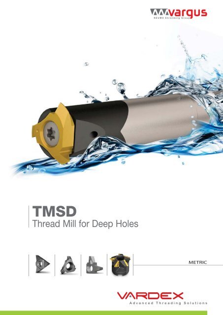
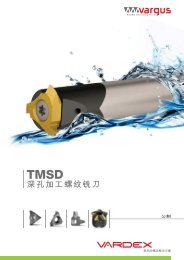
TMSDThread Mill for Deep HolesA multi-flute, high-productivity, and economical solution for milling threads in deep holesWeldonShankCarbideCylindricalShankSee it in actionAmericanButtressVertical Style(7V, 9V, 11V)Tool Overhang (L1) 25-45Cutting Dia. (D2) 10.5-20.0No. of Flutes (Z) 3Tool Overhang (L1) max 65Cutting Dia. (D2) 10.5-20.0No. of Flutes (Z) 3AmericanButtressFor inserts(5.0L, 3/8"L, 5/8"V)Pitch Range 16-2.5 tpiWeldonShankCarbideCylindricalShankSteelCylindricalShankL Style (Mini L)For Small Boresand Short L2A StyleFor Shorter L2Tool Overhang (L1) 29-42Cutting Dia. (D2) 13-17.7No. of Flutes (Z) 1-3Tool Overhang (L1) max 65Cutting Dia. (D2) 13-17.7No. of Flutes (Z) 1-3Tool Overhang (L1) max 144Cutting Dia. (D2) 26-35.3No. of Flutes (Z) 3WeldonShankCarbideCylindricalShankShell MillL Style (3/8" L)For LargeTrapezoid Profilesand ABUTTool Overhang (L1) 50-105Cutting Dia. (D2) 21.6-35.5No. of Flutes (Z) 1-3Tool Overhang (L1) max 120Cutting Dia. (D2) 21.6-33.5No. of Flutes (Z) 1-3Tool Overhang (L1) max 200Cutting Dia. (D2) 48-80No. of Flutes (Z) 5-7WeldonShankCarbideCylindricalShankSteelCylindricalShankShell MillU StyleFor Large PitchesTool Overhang (L1) 40-145Cutting Dia. (D2) 14.75-42No. of Flutes (Z) 1-4Tool Overhang (L1) max 135Cutting Dia. (D2) 14.75-31.0No. of Flutes (Z) 1-4Tool Overhang (L1) max 144Cutting Dia. (D2) 23.3-36.5No. of Flutes (Z) 2-4Tool Overhang (L1) max 200Cutting Dia. (D2) 42-98No. of Flutes (Z) 4-72
Vardex Ordering Code SystemTMSD Inserts21U2I3DB4605TM6VBX71- Insert Size5 - IC5.0 mm2 - IC1/4”3 - IC3/8”4 - IC1/2”5 - IC5/8”7 - IC6.8 mm9 - IC8.5 mm11 - IC10.7 mmIC2 - Insert StyleU -A -L -V -Vertical Style7, 9, 11V -V Style 5/8"3 - Type of InsertI - Internal4 - PitchFull Profile - Pitch Rangemmtpi2.0-8.0 16-2.5Partial Profile - U, A, L Styles Partial Profile - Vertical Stylemm tpi mm tpiDADBDCDDDEDHDKDLDMDNDPDRDT0.5-1.51.5-2.02.5-4.02.0-2.52.5-3.54.0-6.06.0-8.0-2.51.0-2.01.5-3.0-2.0-4.048-1616-1210-69-1210-76-44-311-71024-1116-826-1412-6VAVBVCVDVEVFVGVHVKVJVM0.5-1.0--1.0-2.02.0-3.01.0-1.51.5-2-2.0-2.5--28-2711-916-1024-1212-824-1616-1216-1412-1026-198-75 - Standard60° - Partial Profile 60°55° - Partial Profile 55°TR - Trapez DIN 103ACME - ACMEStub ACME - Stub ACMEABUT - American Buttress6 - SystemTM - TMSD (U, A, L Styles)TM3 - TMSD Vertical7 - Carbide GradeVBX, VTXTMSD Toolholders (U, A, L Styles)C1TM223S4C5146C7178- 65 - 2 U910 111- Shank StyleNone - SteelC - Carbide Shank2- SystemTM3 - No. of Flutes1- 44 - Insert TypeS - Single Point5 - CoolingC - Coolant6 - Shank Dia.9.5 - 407 - Shank TypeW - WeldonC - Cylindrical8 - Cutting Dia.13 - 429 - Max. Tool Overhang29 - 14410 - Insert Size5 - IC5.0 mm2 - IC1/4”3 - IC3/8”4 - IC1/2”11 - Insert StyleUAL12 - Tool ApplicationABUT - For American ButtressTMSD Toolholders (Vertical Style)C1GM2C394C5136- 45 - 7 -78391- Holder TypeNone - Steel ShankC - Carbide Shank9 - Number of Flutes32- SystemGM- Groove Millingand Thread Milling3- CoolingC - Coolant4 - Shank Dia.8, 9, 11.5, 12, 14,15, 20, 255 - Shank StyleC - CylindricalW - Weldon6 - Cutting Dia.10.5-22.07 - Tool Overhang25-658 - Insert Size7 - IC6.8 mm9 - IC8.5 mm11 - IC10.7 mmTMSD Shell Mill (U, L, V Styles)TM142S3C4D425- 16 -637U891- System 2 - No. of FlutesTM4-79 - Tool ApplicationABUT - For ABUT Inserts3 - Insert TypeS - Single Point4 - CoolingC - Coolant5 - Cutting Dia.42 - 986 - Drive Hole Dia.16, 22, 27, 327 - Insert Size3 - IC3/8”4 - IC1/2”5 - IC5/8”8 - Insert StyleU, L, V4
Partial Profile 55ºInternal55°InternalD2ExternalL2rVertical StyleTVertical StyleInsert Style Ordering Code Dimensions (mm) Application (Min. Thread Size)IC tpi Internal D2 T L2 r BSP (G) Partial 55º Toolholder7V9V26-19 7VIVJ55 TM3 … 11.35 0.8 0.07 1⁄4-19 ; 3 ⁄8-19 - CGMC 8C13-40-7-32.91CCGMC 9C13-45-7-3⁄2-14 ;16-14 7VIVH55 TM3 … 12.0 1.0 0.135 ⁄8-14; 93 ⁄16-16; GMC 20W13-25-7-3⁄4-14; 7 ⁄8-14;5 ⁄8-1426-19 9VIVJ55 TM3 … 13.35 0.8 0.09 3⁄8-19 5⁄8-26 ; 3 ⁄8-16 CGMC 11.5C17-50-9-34.23CGMC 12C17-50-9-316-10 9VIVC55 TM3 … 15.4 1.2 0.15 1 ⁄4-16 ;⁄2-1411 ⁄16-14; 3 ⁄4-12; 7 ⁄8-11;3 GMC 20W17-30-9-3⁄4-1011V16-1211-911VIVG55 TM3 …11VIVB55 TM3 …17.819.1 5.50.91.30.160.211⁄2-141-1113⁄16-16 ; 15 ⁄16-127⁄8-11; 1-10; 1 1 ⁄8-98-7 11VIVM55 TM3 … 19.6 1.5 0.36 - 1-8; 1 1 ⁄8-7;CGMC 14C22-60-11-3CGMC 15C22-65-11-3GMC 25W22-45-11-3Vertical Style6
TrapezInternal30°InternalD2ExternalDefined by: DIN 103Tolerance class: 7e/7HL2Vertical StyleTVertical StyleInsert Style Ordering Code Dimensions (mm) Application (Min. Thread Size)IC mm Internal D2 T L2 Trapez Toolholder7V 2.07VI2TR-1 TM3 …7VI2TR-2 TM3 …7VI2TR-3 TM3 …12.3 2.9 1.3TR16x2TR18x2TR20x2CGMC 8C13-40-7-3CGMC 9C13-45-7-3GMC 20W13-25-7-39V 3.09VI3TR-1 TM3 …9VI3TR-2 TM3 …15.4 4.2 1.95TR22x3TR24x3CGMC 11.5C17-50-9-3CGMC 12C17-50-9-3GMC 20W17-30-9-3Stub ACMEInternal29°InternalD2ExternalDefined by: ANSI B1.8: 1988Tolerance class: 2GL2Vertical StyleTVertical StyleInsert Style Ordering Code Dimensions (mm) Application (Min. Thread Size)IC tpi Internal D2 T L2 Stub ACME Toolholder8 7VI8STACME TM3 … 12.35⁄8-8CGMC 8C13-40-7-37V7VI6STACME-1 TM3 …2.9 1.33⁄4-6CGMC 9C13-45-7-3612.77VI6STACME-2 TM3 … 7⁄8-6GMC 20W13-25-7-39VI5STACME-1 TM3 …1-5CGMC 11.5C17-50-9-39V 5 9VI5STACME-2 TM3 … 16.7 4.2 1.951 1 ⁄8-5CGMC 12C17-50-9-39VI5STACME-3 TM3 … 1 1 ⁄4-5GMC 20W17-30-9-311VI4STACME-1 TM3 …1 3 ⁄8-411V 411VI4STACME-2 TM3 … 1 1 ⁄2-4CGMC 14C22-60-11-320.8 5.5 2.6CGMC 15C22-65-11-311VI4STACME-3 TM3 … 1 3 ⁄4-4GMC 25W22-45-11-311VI4STACME-4 TM3 … 2-47
Vertical Toolholders - Weldon ShankCoolant-Thru is recommended, especially when D2>0.7 x nominal thread diameterSpare PartsInsert Style Ordering Code Dimensions mmToolholder L L1 D D1 D2* Insert Screw Torx Key Blade Handle7V GMC 20W13-25-7-3 95 25 20 9 10.5-12.79V GMC 20W17-30-9-3 105 30 20 11.5 13.1-16.711V GMC 25W22-45-11-3 115 45 25 15 17.8-20.8SN2T8-M1(M3.0x0.5x9)SN3T15-M2(M4x0.7x13.5)SN4T20-M3(M5x0.8x15.5)K2T - ---BladeT15- 1 ⁄4BladeT20- 1 ⁄4Smart Handle1⁄4x2Smart Handle1⁄4X2* The tool cutting diameter (D2) is defined by the insert (See pages 5-7)For Correct Clamping:9V11VCurved SurfacesIdentification MarkAlways mount insert with the identification mark between the two curved surfaces on the toolholder8
Vertical Toolholders - Carbide Cylindrical Shank Coolant-Thru is recommended, especially when D2>0.7 x nominal thread diameterHolding deviceL3 (min)Insert Style Ordering Code Dimensions mmSpare Parts7V9V11VToolholder L L1 L3 (min) D D1 D2* Insert Screw Torx Key Blade HandleCGMC 8C13-40-7-340 18 8115CGMC 9C13-45-7-3 45 20 9CGMC 11.5C17-50-9-350 25 11.5125CGMC 12C17-50-9-3 50 26 12CGMC 14C22-60-11-360 30 14135CGMC 15C22-65-11-3 65 32 159 10.5-12.711.5 13.1-16.715 17.8-20.8SN2T8-M1(M3.0x0.5x9)SN3T15-M2(M4x0.7x13.5)SN4T20-M3(M5x0.8x15.5)K2T - ---BladeT15- 1 ⁄4BladeT20- 1 ⁄4Smart Handle1⁄4x2Smart Handle1⁄4X2* The tool cutting diameter (D2) is defined by the insert (See pages 5-7)For Correct Clamping:9V11VCurved SurfacesIdentification MarkAlways mount insert with the identification mark between the two curved surfaces on the toolholder9
Partial Profile 60ºInternal60°Internalr*Lr* r*LLLExternalICICICICr*Mini L StyleU Style2UIDM60 TM…2UIDD60 TM…A StyleL StyleInsert Size Pitch Ordering Code Dimensions (mm)IC L mm mm tpi Internal r * Toolholder5.0L(Mini L)-0.5-1.5 48-16 5LIDA60 TM… 0.04 TM.SC…5L1.0-2.0 24-11 5LIDN60 TM… 0.06 CTM. SC…5LU Style2UIDM60 TM…2UIDD60 TM…Insert Size Pitch Ordering Code Dimensions (mm)IC L mm mm tpi Internal r * Toolholder1/4”U 110.5-1.5 48-16 2UIDA60 TM… 0.05 TM.SC...2U1.5-2.0 16-12 2UIDB60 TM… 0.06 CTM. SC…2U2.0-2.5 9-12 2UIDD60 TM… 0.112.5 10 2UIDM60 TM… 0.11CTM2SC 14C17-65-2U2.5-4.0 10-6 2UIDC60 TM… 0.141.5-2.0 16-12 3UIDB60 TM… 0.06TM.SC...2UCTM. SC…2U3/8”U 162.5-3.5 10-7 3UIDE60 TM… 0.14 TM.SC...3U4.0-6.0 6-4 3UIDH60 TM… 0.251/2”U 22 6.0-8.0 4-3 4UIDK60 TM… 0.30 TM.SC D...4UA StyleInsert Size Pitch Ordering Code Dimensions (mm)IC L mm mm tpi Internal r * Toolholder1/4”A 11 1.5-3.0 16-8 2AIDP60 TM… 0.06 TM.SC...2A3/8”A 16 2.0-4.0 12-6 3AIDT60 TM… 0.08 TM.SC...3A* The indicated radius (r) refers to the insert nose radius onlyL2L2L2PitchU StyleFor Large PitchesPitchA StyleFor Shorter L2PitchMini-L StyleFor Small Bores and Short L210
Partial Profile 55ºInternal55°Internalr*Lr *ExternalICMini L StyleICU StyleL StyleInsert Size Pitch Ordering Code Dimensions (mm)IC tpi Internal r* Toolholder5.0L(Mini L)26-14 5LIDR55 TM… 0.10TM.SC…5LCTM. SC…5LU StyleInsert Size Pitch Ordering Code Dimensions (mm)IC L mm tpi Internal r* Toolholder1/4”U 1148-16 2UIDA55 TM… 0.1116-12 2UIDB55 TM… 0.0811-7 2UIDL55 TM… 0.2416-12 3UIDB55 TM… 0.08TM.SC...2UCTM. SC…2U3/8”U 1611-7 3UIDL55 TM… 0.24 TM.SC...3U6-4 3UIDH55 TM… 0.271/2”U 22 4-3 4UIDK55 TM… 0.50 TM.SC D...4U* The indicated radius (r) refers to the insert nose radius onlyL2L2PitchU StyleFor Large PitchesPitchMini-L StyleFor Small Bores and Short L211
TrapezInternal30°InternalLExternalDefined by: DIN 103Tolerance class: 7e/7HIC3/8" LICMini L StyleICU StyleL StyleInsert Size Pitch Ordering Code ApplicationIC mm Internal Internal Toolholder5.0L(Mini L)3/8"L2.0 5LI2.0TR-1 TM... TR16x2, TR20x22.0 5LI2.0TR-2 TM... TR18x2TM.SC…5LCTM. SC…5L6.0 3LI6.0TR-1 TM... (TR30-36)x6TM1SC 25W21-50-3L;CTM1SC 1 ⁄2"C21-75-3L6.0 3LI6.0TR-2 TM... (TR115-130)x6 TM7SC D80-32-3L7.0 3LI7.0TR TM... (TR38-44)x7TM2SC 25W28-75-3L;CTM2SC 18C28-100-3L8.0 3LI8.0TR-1 TM... (TR46-52)x8TM3SC 32W33-90-3L;CTM3SC 20C33-120-3L8.0 3LI8.0TR-2 TM... (TR175-240)x8 TM7SC D80-32-3LU StyleInsert Size Pitch Ordering Code ApplicationIC L mm mm Internal Internal Toolholder3.02UI3.0TR-1 TM...(TR22-TR30)x32UI3.0TR-2 TM...(TR32-TR60)x31/4”U 114.02UI4.0TR-1 TM...(TR20-TR28)x42UI4.0TR-2 TM...(TR65-TR110)x4See pages 21-225.02UI5.0TR-1 TM...TR22x5; TR28x52UI5.0TR-2 TM...TR24x5; TR26x512
American ACMEInternal29°InternalExternalDefined by: ANSI B1.5: 1988Tolerance class: 3GIC3/8" LL StyleInsert Size Pitch Ordering Code ApplicationIC tpi Internal Internal Toolholder3/8"L5 3LI5ACME TM... 1 1 ⁄4-5ACME3LI4ACME-1 TM...1 3 ⁄8-4ACME3LI4ACME-2 TM...1 1 ⁄2-4ACME43LI4ACME-3 TM...1 3 ⁄4-4ACME3LI4ACME-4 TM...2-4ACMETM1SC 25W21-50-3L;CTM1SC 1 ⁄2"C21-75-3LTM2SC 25W28-75-3L;CTM2SC 18C28-100-3L33LI3ACME-1 TM...3LI3ACME-2 TM...2 1 ⁄4-3ACME2 1 ⁄2-3ACMETM3SC 32W33-90-3L;CTM3SC 20C33-120-3L3LI3ACME-3 TM...2 3 ⁄4-3ACMEStub ACMEInternal29°InternalExternalDefined by: ANSI B1.8: 1988Tolerance class: 2GIC3/8" LL StyleInsert Size Pitch Ordering Code ApplicationIC tpi Internal Internal Toolholder5 3LI5STACME TM... 1 1 ⁄4-5STACME3LI4STACME-1 TM... 1 3 ⁄8-4STACME43LI4STACME-2 TM... 1 1 ⁄2-4STACMETM1SC 25W21-50-3L;CTM1SC 1 ⁄2"C21-75-3L3/8"L3LI4STACME-3 TM...2-4STACME33LI3STACME-1 TM...3LI3STACME-2 TM...2 1 ⁄4-3STACME2 1 ⁄2-3STACMETM3SC 32W33-90-3L;CTM3SC 20C33-120-3L3LI3STACME-3 TM...2 3 ⁄4-3STACME13
Standard Toolholders - Carbide Cylindrical Shank (L Style - Mini L)L3 (min)DD2L2L1 (max)LCoolant-Thru is recommended, especially when D2>0.7 x nominal thread diameterCarbide Cylindrical Shank for Mini-L Style InsertsSpare PartsInsert Size Ordering Code Dimensions (mm) No. of FlutesIC L L1 (max) L2 L3 (min) D D2 Z Insert Screw Torx KeyCTM1SC 09C13-43-5L 109 4320 9.5 13 1CTM2SC 10C14-50-5L 116 50 1.1 22 10 13.5 25.0L(Mini L)CTM3SC 14C18-65-5L 132 65 30 14 17.7 3SN5LTRK7TCTM2SC 10C14-50-5L-ABUT 116 5022 10 14 21.87CTM3SC 14C18-65-5L-ABUT 132 65 30 14 18.2 3Thread Applications for Mini-L Style Toolholders (Carbide Cylindrical Shank)ToolholderMin. Thread ØCTM1SC 09C13-43-5L 13 M16x2D2 ISO Coarse ISO Fine UNC UN/UNF/UNEF/UNS BSP (G) Partial 55° TrapezM14x0.5; M14x0.75; M14.5x1.0;M15x1.5; M17x2.05⁄8-119⁄16-32UN; 9 ⁄16-28UN; 9 ⁄16-27UNS;9⁄16-24UNEF; 5 ⁄8-20UN; 5 ⁄8-18UNF;5⁄8-16UN; 5 ⁄8-14UNS; 5 ⁄8-12UN3⁄8-19 5⁄8-14TR16X2;TR18X2CTM2SC 10C14-50-5L 13.5 M16x2M15x0.5; M15x0.75; M15x1.0;M16x1.5; M17x2.0-5⁄8-32UN; 5 ⁄8-28UN; 5 ⁄8-27UNS;5⁄8-24UNEF; 5 ⁄8-20UN; 5 ⁄8-18UNF;5⁄8-16UN; 5 ⁄8-14UNS; 11 ⁄16-12UN3⁄8-1911⁄16-14TR16X2;TR18X2CTM3SC 14C18-65-5L 17.7 -M19x0.5; M19x0.75; M19x1.0;M20x1.5; M20x2.0-3⁄4-32UN; 3 ⁄4-28UN; 7 ⁄8-27UNS;3⁄4-24UNS; 13 ⁄16-20UNEF; 7 ⁄8-18UNS;13⁄16-16UN; 7 ⁄8-14UNF; 13 ⁄16-12UN1⁄2-14 - TR20X2ToolholderThread ØD2American ButtressCTM2SC 10C14-50-5L-ABUT 14.0(0.875"-4")-16; (0.875"-6")-12;(0.875"-16")-10CTM3SC 14C18-65-5L-ABUT 18.2(1.25"-4")-16; (1.25"-6")-12;(1.25"-16")-1016
Standard Toolholders - Weldon Shank (L Style - 3/8" L)ABUT HolderABUT HolderD1DD2L2L1LCoolant-Thru is recommended, especially when D2>0.7 x nominal thread diameterWeldon Shank for 3/8" L Style InsertsSpare PartsInsert Size Ordering Code Dimensions (mm) No. of FlutesIC Toolholder L L1 L2 D D1 D2 Z Insert Screw Torx KeyTM1SC 25W21-50-3L 115 5025 12.7 21.6 1 SN3TTM2SC 25W28-70-3L 135 70 7.0 25 18.1 28.5 2 SA3T3/8"L TM3SC 32W33-90-3L 158 90 32 22.0 33.5 3 SN3THK3TTM2SC 25W26-80-3L-ABUT 143 8025 20.1 26.4 24.7TM3SC 32W35-105-3L-ABUT 172 105 32 28 35.5 3SA3TThread Applications for 3/8" L Style Toolholders (Weldon Shank)ToolholderMin. Thread ØD2 Trapez American ACME Stub ACMETM1SC 25W21-50-3L 21.6 (TR30-36)x6 1 1 ⁄4-5; 1 3 ⁄8-4; 1 1 ⁄2-4 1 1 ⁄4-5; 1 3 ⁄8-4; 1 1 ⁄2-4TM2SC 25W28-70-3L 28.5 (TR38-44)x7 1 3 ⁄4-4 -TM3SC 32W33-90-3L 33.5 (TR46-52)x8 2-4; 2 1 ⁄4-3; 2 1 ⁄2-3; 2 3 ⁄4-3 2-4; 2 1 ⁄4-3; 2 1 ⁄2-3; 2 3 ⁄4-3ToolholderThread ØD2TM2SC 25W26-80-3L-ABUT 26.4TM3SC 32W35-105-3L-ABUT 35.5American Buttress(1.75"-4")-16; (1.75"-6")-12; (1.75"-6")-10;(1.75"-6")-8; (1.75"-6")-6(2.5"-4")-16; (2.5"-6")-12; (2.5"-6")-10;(2.5"-6")-8; (2.5"-6")-617
Standard Toolholders - Carbide Cylindrical Shank (L Style - 3/8" L)ABUT HolderABUT HolderL3 (min)DD2L2L1 (max)LCoolant-Thru is recommended, especially when D2>0.7 x nominal thread diameterCarbide Cylindrical Shank for 3/8" L Style InsertsSpare PartsInsert Size Ordering Code Dimensions (mm) No. of FlutesIC Toolholder L L1(max) L2 L3(min) D D2 Z Insert Screw Torx KeyCTM1SC 1 ⁄2"C21-75-3L 115 7540 12.7 21.6 1 SN3T3/8"LCTM2SC 18C28-100-3L 155 100 7.0 46 18 28.5 2 SA3TCTM3SC 20C33-120-3L 176 120 46 20 33.5 3 SN3THK3TCTM2SC 20C26-105-3L-ABUT 172.5 105 4.7 40 20 26.4 2 SA3TThread Applications for 3/8" L Style Toolholders (Carbide Cylindrical Shank)ToolholderMin. Thread ØD2 Trapez American ACME Stub ACMECTM1SC 1 ⁄2"C21-75-3L 21.6 (TR30-36)x6 1 1 ⁄4-5; 1 3 ⁄8-4; 1 1 ⁄2-4 1 1 ⁄4-5; 1 3 ⁄8-4; 1 1 ⁄2-4CTM2SC 18C28-100-3L 28.5 (TR38-44)x7 1 3 ⁄4-4 -CTM3SC 20C33-120-3L 33.5 (TR46-52)x8 2-4; 2 1 ⁄4-3; 2 1 ⁄2-3; 2 3 ⁄4-3 2-4; 2 1 ⁄4-3; 2 1 ⁄2-3; 2 3 ⁄4-3ToolholderThread ØD2CTM2SC 20C26-105-3L-ABUT 26.4American Buttress(1.75"-4")-16; (1.75"-6")-12; (1.75"-6")-10;(1.75"-6")-8; (1.75"-6")-618
Shell Mill (L Style - 3/8" L)L2D1≥DaCombi Shell Mill Adaptor is preferableDaD2d(H7)D1Coolant-Thru is recommended, especially when D2>0.7 x nominal thread diameterHShell Mill for 3/8" L Style InsertsInsert Size Ordering Code Dimensions (mm)No. ofFlutesSpare PartsIC Toolholder D1 D2 d(H7) H L2 Z3/8"LInsertScrewTorx KeyHolder ScrewTM7SC D80-32-3L 69.2 80 32 55 7.0 7M16x2.0x40TM5SC D48-22-3L-ABUT 41 48 225 SA3T HK3T M10x1.50x3540 4.7TM6SC D58-27-3L-ABUT 51 58 27 6 M12x1.75x40Thread Applications for 3/8" L Style Toolholders (Shell Mill)ToolholderMin. Thread ØD2 Trapez American ACME Stub ACMETM7SC D80-32-3L 80 (TR115-130)x6; (TR175-240)x8 - -ToolholderThread ØD2TM5SC D48-22-3L-ABUT 48TM6SC D58-27-3L-ABUT 58American Buttress(3.0"-6")-12; (3.0"-6")-10; (3.0"-6")-8;(3.0"-6")-6(4.0"-6")-12; (4.0"-6")-10; (4.0"-6")-8;(4.0"-6")-619
Shell Mill (5/8" V Style)L2D1≥DaCombi Shell Mill Adaptor is preferableDaD2d(H7) D1Coolant-Thru is recommended, especially when D2>0.7 x nominal thread diameterHShell Mill for 5/8" V Style InsertsInsert Size Ordering Code Dimensions (mm)No. ofFlutesSpare PartsIC Toolholder D1 D2 d(H7) H L2 Z InsertTM6SC D88-32-5V6-ABUT 72.5 88 32 47.9 5.355VI4ABUT TM ...65/8"V51.7 8.50 5VI2.5ABUT TM ...TM6SC D88-32-5V8-ABUT 72.5 88 3250.0 7.10 6 5VI3ABUT TM ...InsertScrewTorx KeyHolder ScrewSA5T HK5T M16x2.0x40Thread Applications for 5/8" V Style Toolholders (Shell Mill)ToolholderThread ØD2American ButtressTM6SC D88-32-5V6-ABUT 88 (5.0"-24")-4TM6SC D88-32-5V8-ABUT 88 (6.0"-24")-3; (7.0"-24")-2.520
Standard Toolholders - Carbide Cylindrical Shank (U Style)L3 (min)DD2L2L1 (max)LCoolant-Thru is recommended, especially when D2>0.7 x nominal thread diameterCarbide Cylindrical Shank for U Style InsertsSpare PartsInsert Size Ordering Code Dimensions (mm) No. of FlutesIC L L1 (max) L2 L3 (min) D D2 Z Insert Screw Torx KeyCTM1SC 08C15-40-2U 109 4018 8 14.75* 15.4CTM1SC 11C15-60-2U 120 60 25 10.7 14.75* 1CTM2SC 14C17-65-2U** 132 65 3.4 30 14 17.2** 21/4”U CTM2SC 14C21-65-2U 136 6530 14 20.65* 2SN2THK2TCTM2SC 16C21-80-2U 135 80 34 16 20.65* 25.4CTM3SC 20C26-110-2U 165 110 40 20 26.0* 3CTM4SC 25C31-135-2U 186 135 46 25 31.0* 4Thread Applications for U Style Toolholders (Carbide Cylindrical Shank)ToolholderMin. Thread ØD2 ISO Coarse ISO Fine UNC UN/UNF/UNEF/UNS BSP (G) Partial 55° TrapezCTM1SC 08C15-40-2U 14.75*M18x2.5,M24x3.0,M30x3.5,M36x4.0M16x0.5, M16x0.75,M16x1.0, M17x1.25,M17x1.5, M17x2.03⁄4-10, 7 ⁄8-9,1-8, 1 1 ⁄8-7,1 3 ⁄8-65⁄8-32UN, 5 ⁄8-28UN, 5 ⁄8-27UNS,11⁄16-24UNEF, 11 ⁄16-20UN, 11 ⁄16-16UN,3⁄4-14UNS, 11 ⁄16-12UN1⁄2-14,1-1111⁄16-26, 11 ⁄16-20,11⁄16-16, 11 ⁄16-14,3⁄4-12, 7 ⁄8-11, 3 ⁄4-10,7⁄8-9, 1-8, 1 1 ⁄8-7TR22x3, TR24x3,TR20x4, TR22x5,TR24x5, TR26x5,TR28x5CTM1SC 11C15-60-2U 14.75*M18x2.5,M24x3.0M16x0.5, M16x0.75,M16x1.0, M17x1.25,M17x1.5, M17x2.03⁄4-10, 7 ⁄8-9,1-85⁄8-32UN, 5 ⁄8-28UN, 5 ⁄8-27UNS,11⁄16-24UNEF, 11 ⁄16-20UN, 11 ⁄16-16UN,3⁄4-14UNS, 11 ⁄16-12UN1⁄2-14,1-1111⁄16-26, 11 ⁄16-20,11⁄16-16, 11 ⁄16-14,3⁄4-12, 7 ⁄8-11, 3 ⁄4-10,7⁄8-9TR22x3, TR24x3CTM2SC 14C17-65-2U 17.2**CTM2SC 14C21-65-2U 20.65*CTM2SC 16C21-80-2U 20.65*CTM3SC 20C26-110-2U 26M20x2.5,M22x2.5M24x3.0,M30x3.5,M36x4.0M24x3.0,M30x3.5M30x3.5,M36x4.0CTM4SC 25C31-135-2U 31 M36x4.0M21x2.0 7⁄8-9 7⁄8-10UNS; 13 ⁄16-12UN - - -M22x0.5, M22x0.75,M22x1.0, M23x1.25,M23x1.5, M23x2.0M22x0.5, M22x0.75,M22x1.0, M23x1.25,M23x1.5, M23x2.0M27x0.5, M27x0.75,M28x1.0, M28x1.25,M28x1.5, M29x2.0,M30x2.5, M30x3.0M32x0.5, M32x0.75,M33x1.0, M33x1.25,M33x1.5, M34x2.0,M34x2.5, M35x3.0,M36x3.51-8, 1 1 ⁄8-7,1 3 ⁄8-61-8, 1 1 ⁄8-7,1 3 ⁄8-61 1 ⁄4-7,1 3 ⁄8-61 1 ⁄2-67⁄8-32UN, 7 ⁄8-28UN, 7 ⁄8-27UNS,7⁄8-24UNS, 7 ⁄8-20UNEF, 1-18UNS,15⁄16-16UN, 1-14UNS, 15 ⁄16-12UN,1-10UNS7⁄8-32UN, 7 ⁄8-28UN, 7 ⁄8-27UNS,7⁄8-24UNS, 7 ⁄8-20UNEF, 1-18UNS,15⁄16-16UN, 1-14UNS, 15 ⁄16-12UN,1-10UNS1 1 ⁄8-28UN, 1 1 ⁄8-24UNS,1 1 ⁄8-20UN, 1 1 ⁄8-18UNEF, 1 1 ⁄8-16UN,1 1 ⁄8-14UNS, 1 1 ⁄8-12UNF, 1 3 ⁄8-10UNS,1 7 ⁄16-8UN1 5 ⁄16-28UN, 1 1 ⁄2-24UNS, 1 1 ⁄2-20UN,1 1 ⁄2-18UNEF, 1 3 ⁄8-16UN, 1 3 ⁄8-14UNS,1 3 ⁄8-12UNF, 1 3 ⁄8-10UNS, 1 7 ⁄16-8UN3⁄4-14,1-113⁄4-14,1-117⁄8-14,1-111 1 ⁄8-111-26, 1-20, 1-16,1-12, 1-10, 1 1 ⁄8-9,1-8, 1 1 ⁄8-71-26, 1-20, 1-16,1-12, 1-10, 1 1 ⁄8-9,1-8, 1 1 ⁄8-71 1 ⁄8-26, 1 1 ⁄8-20,1 3 ⁄16-16, 1 3 ⁄16-12,1 3 ⁄16-8, 1 1 ⁄4-71 5 ⁄16-26, 1 5 ⁄16-20,1 3 ⁄8-16, 1 3 ⁄8-12,1 7 ⁄16-8(TR26-TR60)x3,TR28x4,(TR65-TR110)x4,TR28x5(TR26-TR60)x3(TR40-TR60)x3(TR65-TR110)x4(TR50-TR60)x3(TR65-TR110)x4* For TR inserts use the CNC program (D2+0.25mm)* * To be used only with inserts 2UIDD60TM... or 2UIDM60TM...For insert 2UIDD60 TM... use the CNC program (D2+0.7mm)22
Standard Toolholders - Steel Cylindrical Shank (U Style)L3 (min)DD2L2L1 (max)LCoolant-Thru is recommended, especially when D2>0.7 x nominal thread diameterSteel Cylindrical Shank for U Style InsertsSpare PartsInsert Size Ordering Code Dimensions (mm) No. of FlutesIC L L1 (max) L2 L3 (min) D D2 Z Insert Screw Torx KeyTM2SC 18C23-86-2U 166 8640 18 23.3 21/4”U TM3SC 20C26-105-2U 186 105 5.4 40 20 26 3SN2THK2TTM4SC 25C31-115-2U 196 115 46 25 31 43/8”UTM3SC 25C36-125-3U 193 12546 25 36.5 38.0TM3SC 28C36-144-3U 222 144 60 28 36.5 3SA3THK3TThread Application for U Style Toolholders (Steel Cylindrical Shank)ToolholderMin. Thread ØTM2SC 18C23-86-2U 23.3D2 ISO Coarse ISO Fine UNC UN/UNF/UNEF/UNS BSP (G) Partial 55°M27x3.0, M30x3.5,M36x4.0TM3SC 20C26-105-2U 26 M30x3.5, M36x4.0TM4SC 25C31-115-2U 31 M36x4.0M24x0.5, M25x0.75, M25x1.0,M25x1.25, M26x1.5, M26x2.0,M27x2.5M27x0.5, M27x0.75, M28x1.0,M28x1.25, M28x1.5, M29x2.0,M30x2.5, M30x3.0M32x0.5, M32x0.75, M33x1.0,M33x1.25, M33x1.5, M34x2.0,M34x2.5, M35x3.0, M36x3.51 1 ⁄8-71 1 ⁄4-7,1 3 ⁄8-61 1 ⁄2-61-32UN, 1-28UN, 1-27UN,1-24UNS, 1-20UNEF,1-18UNS, 1-16UN,1-14UNS, 1 1 ⁄16-12UN,1 1 ⁄8-10UNS, 1 1 ⁄8-8UN1 1 ⁄8-28UN, 1 1 ⁄8-24UNS,1 1 ⁄8-20UN, 1 1 ⁄8-18UNEF,1 1 ⁄8-16UN, 1 1 ⁄8-14UNS,1 1 ⁄8-12UNF, 1 3 ⁄8-10UNS,1 7 ⁄16-8UN1 5 ⁄16-28UN, 1 1 ⁄2-24UNS,1 1 ⁄2-20UN, 1 1 ⁄2-18UNEF,1 3 ⁄8-16UN, 1 3 ⁄8-14UNS,1 3 ⁄8-12UNF, 1 3 ⁄8-10UNS,1 7 ⁄16-8UN3⁄4-14,1-117⁄8-14,1-111 1 ⁄8-111-26, 1-20,1 1 ⁄8-16, 1 1 ⁄8-12,1 1 ⁄8-9, 1 1 ⁄8-71 1 ⁄8-26, 1 1 ⁄8-20,1 3 ⁄16-16, 1 3 ⁄16-12,1 3 ⁄16-8, 1 1 ⁄4-71 5 ⁄16-26, 1 5 ⁄16-20,1 3 ⁄8-16, 1 3 ⁄8-12,1 7 ⁄16-8TM3SC 25C36-125-3UTM3SC 28C36-144-3U36.5M42.5x4.5, M48x5.0,M56x5.5, M64x6.0M39x1.5, M40x2.5, M41x3.0,M42x3.5, M42x4.01 3 ⁄4-5,2-4.5,2 1 ⁄2-41 9 ⁄16-16UN, 1 5 ⁄8-14UNS,1 9 ⁄16-12UN, 1 5 ⁄8-10UNS,1 5 ⁄8-8UN, 1 5 ⁄8-6UN1 1 ⁄4-111 5 ⁄8-16, 1 5 ⁄8-12,1 5 ⁄8-8, 1 7 ⁄8-6,1 3 ⁄4-5The length of cylindrical shank toolholders can be modified to reduce chatter (vibration).Note: The length of the shank inside the clamping device should be at minimum L3.23
Shell Mill (U Style)L2D2d (H7) D1D1≥DaCombi Shell Mill Adaptoris preferableDaHCoolant-Thru is recommended, especially when D2>0.7 x nominal thread diameterAdaptor not includedShell Mill for U Style InsertsInsert Size Ordering Code Dimensions (mm)No. ofFlutesSpare PartsIC D1 D2 d(H7) H L2 Z3/8”U1/2”UTM4SC D42-16-3U 34 42 16 40 8.0 4TM5SC D48-22-3U 40 48 22 40 8.0 5TM6SC D56-22-3U 48 56 22 40 8.0 6InsertScrewSN3TTorx KeyHK3THolder ScrewSA5T-C5 (M8x1.25x28)TM6SC D88-27-4U 76 88 27 50 10.8 6M12x1.75x40SA4T HK4TTM7SC D98-32-4U 85 98 32 55 10.8 7 M16x2.0x40HolderScrewdriverTK5TM10x1.50x35 --Thread Application for U Style Shell MillToolholderMin. Thread ØTM4SC D42-16-3U 42TM5SC D48-22-3U 48D2 ISO Coarse ISO Fine UNC UN/UNF/UNEF/UNS BSP (G) Partial 55°M48x5.0,M56x5.5,M64x6.0,M56x5.5,M64x6.0TM6SC D56-22-3U 56 M64x6.0M45x1.5, M45x2.0, M46x2.5,M48x3.0, M48x3.5, M48x4.0M52x1.5, M52x2.0, M52x2.5,M52x3.0, M55x4.0M60x1.5, M60x2.0, M60x2.5,M60x3.0, M64x4.02-4.5,2 1 ⁄2 - 42 1 ⁄4 - 4.5,2 1 ⁄2 - 42 1 ⁄2 - 41 3 ⁄4-16UN, 1 3 ⁄4-14UNS, 1 13 ⁄16-12UN,1 13 ⁄16-8UN, 1 15 ⁄16-6UN2-16UN, 2-14UN, 2-12UN,2 1 ⁄4-10UNS, 2 1 ⁄8-8UN, 2 1 ⁄8-6UN2 3 ⁄8-16UN, 2 3 ⁄8-14UN, 2 3 ⁄8-12UN,2 1 ⁄2-10UNS, 2 3 ⁄8-8UN, 2 1 ⁄2-6UN1 1 ⁄2 - 111 3 ⁄4 - 112 - 111 7 ⁄8-16, 1 7 ⁄8-12, 1 7 ⁄8-8,1 7 ⁄8-6, 2-4.5TM6SC D88-27-4U 88 - M95x6.0, M125x8 4- 4 4 1 ⁄4-4UN - 4-3, 4 1 ⁄4-4TM7SC D98-32-4U 98 - M105x6.0, M125x8 - 4 1 ⁄4-4UN - 4 1 ⁄4-42-16, 2 1 ⁄4-12, 2 1 ⁄4-8, 2 1 ⁄4-6,3-5, 3 1 ⁄2-4.5, 2 1 ⁄4-42 1 ⁄2-16, 2 1 ⁄2-12, 2 1 ⁄2-8,2 3 ⁄4-6, 3-5, 3 1 ⁄2-4.5, 4 1 ⁄4-424
Standard Toolholders - Steel Cylindrical Shank (A Style)L3 (min)DD2L2L1 (max)LCoolant-Thru is recommended, especially when D2>0.7 x nominal thread diameterSteel Cylindrical Shank for A-Style InsertsSpare PartsInsert Size Ordering Code Dimensions (mm) No. of FlutesIC L L1 (max) L2 L3 (min) D D2 Z Insert Screw Torx Key1/4”A TM3SC 20C26-105-2A 184 105 3.0 40 20 26 3 SN2T HK2T3/8”A TM3SC 28C35-144-3A 218 144 4.0 46 28 35.3 3 SA3T HK3TThread Application for A-Style Toolholders (Steel Cylindrical Shank)ToolholderMin. Thread ØTM3SC 20C26-105-2A 26 -TM3SC 28C35-144-3A 35.3 -D2 ISO Coarse ISO Fine UNC UN/UNF/UNEF/UNS BSP (G)M28x1.5, M29x2.0,M30x2.5, M30x3.0M38x2.0, M39x2.5,M39x3.0, M40x4.0--1 1 ⁄8-16UN, 1 1 ⁄8-14UNS, 1 3 ⁄16-12UN,1 1 ⁄4-10UNS, 1 3 ⁄16-8UN1 9 ⁄16-12UN, 1 5 ⁄8-10UNS, 1 5 ⁄8-8UN,1 5 ⁄8-6UN--The length of cylindrical shank toolholders can be modified to reduce chatter (vibration).Note: The length of the shank inside the clamping device should be at minimum L3.25
Recommended Grades, Cutting Speeds Vc [m/min] and Feed f [mm/tooth]MaterialGroupPSteelMStainlessSteelKCast IronN(K)Non-FerrousMetalsS(M)Heat ResistantMaterialVc [m/min]Feed* f [mm/tooth] byCutting Dia. (D2)HardnessMaterialBrinell HBVBX VTX 13-23 24-42 Shell Mill1Low carbon (C=0.1-0.25%) 125 100-210 90-180 0.20-0.32 0.30-0.50 0.30-0.752 Unalloyed steelMedium carbon (C=0.25-0.55%) 150 100-180 90-170 0.20-0.32 0.30-0.50 0.30-0.753 High Carbon (C=0.55-0.85%) 170 100-170 90-160 0.15-0.23 0.25-0.35 0.25-0.524Non hardened 180 60-90 90-155 0.17-0.28 0.28-0.45 0.28-0.675Low alloy steel(alloying elements≤5%)Hardened 275 80-150 80-160 0.15-0.28 0.25-0.45 0.25-0.676 Hardened 350 70-140 70-150 0.15-0.25 0.25-0.40 0.25-0.607 High alloy steelAnnealed 200 60-130 70-115 0.15-0.22 0.20-0.30 0.20-0.458 (alloying elements>5%) Hardened 325 70-110 60-100 0.13-0.21 0.18-0.30 0.18-0.459Low alloy (alloying elements 5%) 225 70-120 70-130 0.12-0.22 0.17-0.30 0.17-0.4511 Stainless steelNon hardened 200 100-170 120-180 0.15-0.22 0.22-0.34 0.22-0.5012 FerriticHardened 330 100-170 120-180 0.16-0.23 0.21-0.32 0.21-0.4813 Stainless steelAustenitic 180 70-140 100-140 0.15-0.25 0.25-0.40 0.25-0.6014 AusteniticSuper Austenitic 200 70-140 100-140 0.12-0.20 0.17-0.26 0.17-0.3915 Stainless steelNon hardened 200 70-140 100-140 0.16-0.24 0.25-0.37 0.25-0.5516 Cast FerriticHardened 330 70-140 100-140 0.12-0.20 0.17-0.26 0.17-0.3917 Stainless steelAustenitic 200 70-120 100-120 0.15-0.22 0.20-0.30 0.20-0.4518 Cast austeniticHardened 330 70-120 100-120 0.12-0.20 0.17-0.26 0.17-0.3928 MalleableFerritic (short chips) 130 60-130 100-120 0.16-0.24 0.25-0.37 0.25-0.5529 Cast ironPearlitic (long chips) 230 60-120 80-100 0.15-0.22 0.20-0.30 0.20-0.4530Low tensile strength 180 60-130 80-100 0.15-0.22 0.22-0.34 0.22-0.50Grey cast iron31 High tensile strength 260 60-100 80-100 0.15-0.22 0.20-0.30 0.20-0.4532Ferritic 160 60-125 80-100 0.10-0.20 0.15-0.25 0.15-0.37Nodular SG iron33 Pearlitic 260 50-90 60-90 0.15-0.22 0.20-0.30 0.20-0.4534 Aluminium alloysNon aging 60 100-250 0.30-0.50 0.60-1.00 0.60-1.5035 WroughtAged 100 100-180 0.28-0.50 0.50-0.90 0.50-1.2036Cast 75 150-400 0.28-0.50 0.50-0.90 0.50-1.20Aluminium alloys37 Cast & aged 90 150-280 0.25-0.40 0.40-0.60 0.40-0.9038 Aluminium alloys Cast Si 13-22% 130 80-150 0.28-0.50 0.50-0.90 0.50-1.2039 Copper andBrass 90 120-210 100-200 0.30-0.50 0.60-1.00 0.60-1.5040 Copper alloysBronze and non leaded copper 100 120-210 100-200 0.28-0.50 0.50-0.90 0.50-1.2019Annealed (Iron based ) 200 20-45 20-40 0.09-0.15 0.12-0.22 0.12-0.3320 High temperature Aged (Iron based) 280 20-30 20-30 0.07-0.13 0.10-0.20 0.10-0.3021 alloysAnnealed (Nickel or Cobalt based) 250 15-20 15-20 0.08-0.15 0.08-0.20 0.08-0.30Vardex No.22 Aged (Nickel or Cobalt based) 350 10-15 10-15 0.08-0.15 0.08-0.20 0.08-0.3023Pure 99.5 Ti 400Rm 70-140 70-120 0.07-0.13 0.10-0.20 0.10-0.30Titanium alloys24 α+β alloys 1050Rm 20-50 20-50 0.07-0.13 0.10-0.20 0.10-0.30H(K)HardenedMaterial2545-50HRc 15-45 15-45 0.05-0.12 0.05-0.18 0.05-0.27Extra hard steelHardened & tempered26 51-55HRc 15-40 15-40 0.05-0.12 0.05-0.18 0.05-0.27* When using a Shell Mill toolholder, the feed can be increased by 50%* For 3/8"L it is recommended to machine in two passes and decrease the feed by 40%GradesGradeApplicationU StyleA StyleMini-L Style3/8" L StyleVertical StyleV StyleVBXTiCN coated carbide grade.Excellent grade for Steels and General Use.VTXTiAlN coated carbide grade.Ideal for Stainless Steels.26
VARGUSTool Selection andCNC Program GeneratorThe most popular and advanced thread turning andthread milling software on the market today.Now available in 2 Versions at www.vargus.com:Online VersionDownloadable VersionOnline interactive softwareFor all web browsing environmentsMost updated version always onlineStandalone software applicationMS Windows OS-based programAutomatic updates27
TMSDThread Mill for Deep HolesVisit VARGUS mrktg@vargus.com www.vargus.com221-01161METRIC EE07/2013EDITION 02


