HT1632C datasheet - Adafruit
HT1632C datasheet - Adafruit HT1632C datasheet - Adafruit
HT1632C 24 ROW 16 COM example (direct drive)+ 5 + 5+ 5 !9 44 ,, ) 6 ) + 7+ 54 9 9 44 9 !4 ,, ) 6 ) 0 6 $ ! + = I J A H 5 +5 ; +" 4 9, H E L A H I+ $ + + # , H E L A H I4 9 4 9 !+ + #44 - , = J H E N+ 54 9 9 44 9 !4 ,, ) 6 ) 0 6 $ ! + 5 = L A 5 +5 ; +" 4 9, H E L A H I+ $ + + # , H E L A H I4 9 4 9 !+ + #44 - , = J H E N+ 54 9 9 44 9 !4 ,, ) 6 ) 0 6 $ ! + 5 = L A 5 +5 ; +" 4 9, H E L A H I+ $ + + # , H E L A H I4 9 4 9 !+ + #44 - , = J H E NNote:1. It also can set cascade mode by software. User must set the Master in master mode and Slaves in slavemode with command. The CS pin must be connected to MCU individually for independent read and write.2. Values of the R resistors are selected depending on the power consumption of the LEDs.Rev. 1.20 18 June 28, 2011
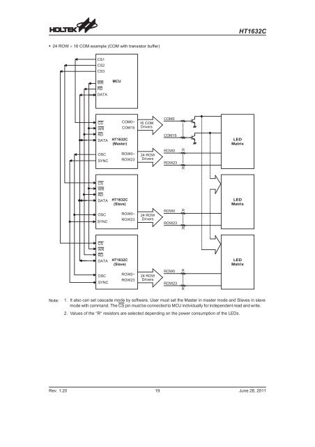
HT1632C 24 ROW 16 COM example (COM with transistor buffer)+ 5 + 5+ 5 !9 44 ,, ) 6 ) + 7+ 5+ 9 4+ #4 ,, ) 6 ) 0 6 $ ! + = I J A H 5 + 4 9 5 ; + 4 9 ! $ + , H E L A H I" 4 9, H E L A H I+ + #4 9 44 9 !4 - , = J H E N+ 59 44 ,, ) 6 ) 0 6 $ ! + 5 = L A - , = J H E N 5 + 4 9 4 9 !5 ; +" 4 9, H E L A H I4 9 4 9 !44+ 59 44 ,, ) 6 ) 0 6 $ ! + 5 = L A 5 +5 ; +4 9 4 9 !" 4 9, H E L A H I4 9 44 9 !4 - , = J H E NNote:1. It also can set cascade mode by software. User must set the Master in master mode and Slaves in slavemode with command. The CS pin must be connected to MCU individually for independent read and write.2. Values of the R resistors are selected depending on the power consumption of the LEDs.Rev. 1.20 19 June 28, 2011
- Page 1 and 2: HT1632C328 &2416 LED DriverFeatures
- Page 3 and 4: HT1632CAbsolute Maximum RatingsSupp
- Page 5 and 6: HT1632CFunctional DescriptionDispla
- Page 7 and 8: HT1632CSystem OscillatorThe HT1632C
- Page 9 and 10: HT1632CDigital DimmingThe Display D
- Page 11 and 12: HT1632CWRITE Mode Command Code =10
- Page 13 and 14: HT1632CApplication CircuitsLow Powe
- Page 15 and 16: HT1632CHigh Power LED Application (
- Page 17: HT1632C 32 ROW 8 COM example (COM
- Page 21 and 22: HT1632CCommand SummaryName ID Comma
- Page 23 and 24: HT1632CPackage Information52-pin QF
<strong>HT1632C</strong> 24 ROW 16 COM example (COM with transistor buffer)+ 5 + 5+ 5 !9 44 ,, ) 6 ) + 7+ 5+ 9 4+ #4 ,, ) 6 ) 0 6 $ ! + = I J A H 5 + 4 9 5 ; + 4 9 ! $ + , H E L A H I" 4 9, H E L A H I+ + #4 9 44 9 !4 - , = J H E N+ 59 44 ,, ) 6 ) 0 6 $ ! + 5 = L A - , = J H E N 5 + 4 9 4 9 !5 ; +" 4 9, H E L A H I4 9 4 9 !44+ 59 44 ,, ) 6 ) 0 6 $ ! + 5 = L A 5 +5 ; +4 9 4 9 !" 4 9, H E L A H I4 9 44 9 !4 - , = J H E NNote:1. It also can set cascade mode by software. User must set the Master in master mode and Slaves in slavemode with command. The CS pin must be connected to MCU individually for independent read and write.2. Values of the R resistors are selected depending on the power consumption of the LEDs.Rev. 1.20 19 June 28, 2011


