BUCHHOLZ RELAY type BS 25 - TERMAN
BUCHHOLZ RELAY type BS 25 - TERMAN
BUCHHOLZ RELAY type BS 25 - TERMAN

You also want an ePaper? Increase the reach of your titles
YUMPU automatically turns print PDFs into web optimized ePapers that Google loves.
Description and general specifications<br />
Construction<br />
Operation<br />
Operating instructions and maintenance<br />
Finished product quality control tests<br />
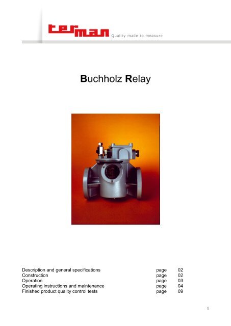
Buchholz Relay<br />
page<br />
page<br />
page<br />
page<br />
page<br />
02<br />
02<br />
03<br />
04<br />
09<br />
1
Description and general specifications.<br />
The gas and oil actuated (Buchholz) relay is designed to detect faults as well to minimize the propagation of<br />
any damage which might occur within oil-filled transformers, capacitors and reactors supplied with oil<br />
conservator.<br />
The relay is therefore particularly effective in case of:<br />
� Short-circuited core laminations<br />
� Broken-down core bolt insulation<br />
� Bad contacts<br />
� Overheating of some part of the windings<br />
� Short-circuits between phases<br />
� Earth faults puncture of bushing insulators inside tank<br />
Furthermore the relay can prevent the development of conditions leading to a fault in the transformer, such<br />
as the falling of the oil level owing to leaks, or the ingress of air as a result of defects in the oil circulating<br />
system.<br />
Construction.<br />
Casing : non porous weatherproof compact<br />
casting of light aluminium alloy painted.<br />
Cover : non porous weatherproof compact<br />
casting of light aluminium alloy painted. On the<br />
cover are located : the terminal box, the valve of<br />
pneumatic test, the breather cock, the button for<br />
mechanical test of alarm and trip circuits.<br />
Inspection windows : special tempered glass<br />
with graduated scale in cm 3 .<br />
Contacts : they can be mercury switches or<br />
magnetic actuated switches (reed contacts). On<br />
request itís possible to supply change-over<br />
switches.<br />
Switches characteristics :<br />
ï rated voltage : 24 � <strong>25</strong>0V AC or DC<br />
ï rated current : 0,5A (10000 tests)<br />
ï breaking capacity : 2A AC (cos= 0,4 � <strong>25</strong>% -<br />
50Hz) 2A DC (T=L/R=40msec).<br />
Mechanical protection degree : IP 54<br />
Insulation : 2000V 50Hz between terminals and<br />
earth for a 60 seconds time.<br />
Working temperature : oil temperature range: -<br />
<strong>25</strong> / +115 C.<br />
Vibration test (in normal operative conditions) :<br />
ï oscillation amplitude : 2mm<br />
ï time diagram :<br />
0Hz � 100Hz 30 sec.<br />
100Hz (200 vibrations/sec.) 60 sec.<br />
100Hz � 0Hz. 30 sec.<br />
Contacts capacity to withstand vibrations :<br />
Mercury sw :<br />
150 horizontal vibrations/sec. (75Hz) first signals<br />
of closing contacts 120 vertical vibrations/sec.<br />
(75Hz) first signals of closing contacts.<br />
Magnetic sw :<br />
200 horizontal vibrations/sec. (100Hz) no one<br />
signal of closing contacts<br />
200 vertical vibrations/sec. (100Hz)<br />
no one signal of closing contacts.<br />
2
Operation.<br />
Slight faults : when a slight fault occurs in the transformer, the small bubbles of gas, which pass upwards to<br />
the conservator, are trapped in the relay housing, thus causing its oil level to fall. As a result, the upper float<br />
rotates on its hub and operates the alarm switch, thus operating an external alarm device.<br />
Serious faults : when a serious fault occurs in the transformer, the gas generation is violent and causes the<br />
oil to rush through the connecting pipe to the conservator.<br />
In the relay this oil surge hits the flap fitted on the lower float (located in front of the hole for the oil passage)<br />
and causes the rotation of the float itself, thus operating the tripping switch and disconnecting the<br />
transformer. The float remains in the trip position even if the oil flow comes to a stop (the reset is done by<br />
means of the push-button).<br />
The tripping device is regulated in such a way that in transformers having forced oil cooling, the surges<br />
resulting from the starting of the oil circulating pump will not cause mal-operation of the relay.<br />
An oil leak in the transformer causes the oil level in the relay to fall, thus operating first the alarm (upper)<br />
float and then the tripping (lower) float.<br />
The ingress of air into the transformer, arising from defects in the oil circulating system or from other<br />
causes, operates the alarm float.<br />
Checking after actuation of the relay<br />
When the signal is given, the colour of the gas should be observed through the inspection-windows.<br />
Draw a gas sample and analyse it by means of the proper analyser. It should be noted that, usually :<br />
ï whitish gas is caused by electric arcing in contact with paper, cotton or silk<br />
ï yellowish gas is due to wood and cardboard<br />
ï greyish gas is caused by a breakdown of the magnetic circuit<br />
ï black gas is caused by free arcing in the oil.<br />
If the relay disconnects the transformer, similar checks should be made to determine composition and<br />
quantity of gas collected by the equipment<br />
In any case never put back the transformer into service without having detected the cause of fault and<br />
having repaired it.<br />
3
Operating instructions and maintenance.<br />
Mounting instructions : the Buchholz relay is mounted on the connecting pipe between the transformer and<br />
the conservator : the arrow marked on the relay cover must point toward the oil conservator.<br />
The pipe should not contain any right-angle elbow. Pipe diameter should correspond to the diameter of the<br />
relayís hole for the oil passage. The pipe must be arranged to slope upwards towards the conservator at an<br />
angle of 1 up 5 degrees to the horizontal.<br />
Electric wiring diagram : inside junction box cover itís possible to find electric wiring diagram that consents<br />
the operator to effect the connection of the relay to alarm and trip circuits and to earth. Once electrical<br />
circuits are connected it is advisable to effect the mechanical test of the alarm and trip circuits by means of<br />
the apposite button located on the relayís cover.<br />
Caution : gradually press the button until first alarm contact is obtained, and afterwards also the trip contact<br />
is activated. The push-button is self returning thereby freeing the signalling devices of the relay as soon as<br />
the pressing action upon the button is discontinued.<br />
Signalling : ï in case of gas accumulation : alarm<br />
ï in case of lack of oil : trip<br />
ï in case of oil surge : trip<br />
Maintenance :<br />
No particular maintenance is required. Only, on regular basis - typically once a year, schedule inspections to<br />
verify that there are no oil leakages and to check the correct working of the contacts.<br />
The check can be done in two ways :<br />
1 ) MECHANICAL TEST : by pushing the mechanical test button - pos. 8 on Buchholz drawings - on the top<br />
of the relay casing - after unscrewing its cover<br />
2 ) PNEUMATIC TEST : by injecting air into the relay with a suitable pump (can be supplied by <strong>TERMAN</strong> in<br />
case on request) through the valve for pneumatic test - pos. 7 on buchholz relay drawings - until the floats<br />
rotate thus causing contacts actuation. After testing discharge the injected air by means of the breatherdischarge<br />
cock on the cover of the relay casing - pos. 6 on Buchholz drawings .<br />
In case the window transparents are dirty, thus reducing the readability of the oil level inside of the buchholz<br />
casing, you can clean them with a soft cloth, water and soap.<br />
4
D d1<br />
S<br />
<strong>BUCHHOLZ</strong> <strong>RELAY</strong> <strong>type</strong> BG <strong>25</strong> ñ DIN 4<strong>25</strong>66<br />
L<br />
10<br />
B<br />
A<br />
POS DESCRIPTION<br />
1-2 RELEASE TERMINALS<br />
3-4 ALARM TERMINALS<br />
5 EARTH TERMINAL<br />
6 BREATHER COCK<br />
7 VALVE OF PNEUMATIC TEST<br />
8 MECHANICAL TEST OF THE<br />
ALARM/RELEASE CIRCUIT<br />
9 CABLE GLAND PG 16<br />
10 DRAIN PLUG<br />
Type A B D E L S d1 gas vol. WEIGHT<br />
BG<strong>25</strong> 215 160 R1-1/2"<strong>BS</strong>P 140 185 20 <strong>25</strong> 1<strong>25</strong> cm3 2,2 kg.<br />
9<br />
6<br />
8<br />
7<br />
5<br />
1-2<br />
3-4<br />
E<br />
5
<strong>BUCHHOLZ</strong> <strong>RELAY</strong>S <strong>type</strong>s BR <strong>25</strong> /50/80 ñ DIN 4<strong>25</strong>66<br />
6<br />
8<br />
7<br />
L<br />
10<br />
5<br />
S<br />
B<br />
1-2<br />
3-4<br />
A<br />
E<br />
9<br />
d1<br />
d3<br />
D<br />
d2<br />
POS DESCRIPTION<br />
1-2 RELEASE TERMINALS<br />
3-4 ALARM TERMINALS<br />
5 EARTH TERMINAL<br />
6 BREATHER COCK<br />
7 VALVE OF PNEUMATIC TEST<br />
8 MECHANICAL TEST OF THE<br />
ALARM/RELEASE CIRCUIT<br />
9 CABLE GLAND PG 16<br />
10 DRAIN PLUG<br />
Type A B C D E L S d1 d2 d3 N holes gas vol. WEIGHT<br />
BR<strong>25</strong> 215 160 85 115 140 200 17 <strong>25</strong> 14 68 4 1<strong>25</strong> cm3 2,9 kg.<br />
BR50 <strong>25</strong>4 178 1<strong>25</strong> 165 140 195 18 50 18 102 4 235 cm3 4,9 kg.<br />
BR80 293 193 160 200 140 195 18 80 18 138 4/8 235 cm3 5,8 kg.<br />
C<br />
6
<strong>BUCHHOLZ</strong> <strong>RELAY</strong> <strong>type</strong> <strong>BS</strong> <strong>25</strong> ñ <strong>BS</strong> STANDARD<br />
6<br />
8<br />
7<br />
L<br />
10<br />
S<br />
B<br />
5<br />
A<br />
1-2<br />
d2<br />
E<br />
3-4<br />
9<br />
d1<br />
C<br />
D<br />
C<br />
D<br />
POS DESCRIPTION<br />
1-2 RELEASE TERMINALS<br />
3-4 ALARM TERMINALS<br />
5 EARTH TERMINAL<br />
6 BREATHER COCK<br />
7 VALVE OF PNEUMATIC TEST<br />
8 MECHANICAL TEST OF THE<br />
ALARM/RELEASE CIRCUIT<br />
9 CABLE GLAND PG 16<br />
10 DRAIN PLUG<br />
Type A B C D E L S d1 d2 N holes gas vol. WEIGHT<br />
<strong>BS</strong><strong>25</strong> 215 160 50,8 75 140 127 12 <strong>25</strong> M10 4 1<strong>25</strong> cm3 2,2 kg.<br />
7
<strong>BUCHHOLZ</strong> <strong>RELAY</strong> <strong>type</strong> <strong>BS</strong> 50-80 ñ <strong>BS</strong> STANDARD<br />
6<br />
8<br />
7<br />
L<br />
10<br />
S<br />
5<br />
B<br />
1-2<br />
3-4<br />
POS DESCRIPTION<br />
1-2 RELEASE TERMINALS<br />
3-4 ALARM TERMINALS<br />
5 EARTH TERMINAL<br />
6 BREATHER COCK<br />
7 VALVE OF PNEUMATIC TEST<br />
8 MECHANICAL TEST OF THE<br />
ALARM/RELEASE CIRCUIT<br />
9 CABLE GLAND PG 16<br />
10 DRAIN PLUG<br />
Type A B C D E L S d1 d2 d3 N holes gas vol. WEIGHT<br />
<strong>BS</strong>50 288 178 110 140 140 185 14 50 11 - 6 235cm3 4,1 kg.<br />
<strong>BS</strong>80 288 178 130 160 140 185 14 80 11 - 6 235cm3 4,3 kg.<br />
A<br />
E<br />
9<br />
d1<br />
C<br />
D<br />
d2<br />
8
Finished product quality control tests.<br />
Hydraulic test for tightness for the body : the aluminium alloy casing is filled with oil at the temperature of<br />
90 C and at the pressure of 300 kpa.<br />
After 4 hours no leakages must be observed.<br />
The same test is carried out for floats and switches.<br />
Dimensional check.<br />
Hydraulic test for tightness of the finished relay : the test is carried out by filling the Buchholz relay with<br />
oil at the temperature of 90 C and at the pressure of 200 kpa. Said test lasts 4 hours. During this period no<br />
oil leakage is admitted.<br />
Manual and pneumatic inspection of the electric contacts actuation : This test is carried out both on<br />
alarm and trip circuits. Itís performed by means of visual indicators mounted on a panel-board.<br />
Check of tripping velocity : performed by mounting the relay on a oil filled pipeline. By means of a<br />
calibrated flow meter and of suitable visual indicators mounted on a panel-board.<br />
Check of instrument mechanical protection degree : IP 54.<br />
Insulation test : carried out by means of a microprocessor controlled testing unit.<br />
Terman '90 S.r.l., Via Ghisalba, 13-20/21, 20021 Bollate (MI) ñ Italy. Tel: +39 02 38 30 37 12, Fax: +39 02 38 30 37 19,<br />
E-Mail info@terman.com, www.terman.com<br />
C.F./P. IVA IT 09970270154 ñ C.C.I.A.A. 1332904 ñ Trib. Milano Reg. Soc. 302729 ñ Cap. Soc. Ä 119.000<br />
I EDITION AUGUST 2006<br />
9