

HE359DAC007/HE359DAC107 - Horner APG Canada
HE359DAC007/HE359DAC107 - Horner APG Canada
HE359DAC007/HE359DAC107 - Horner APG Canada

You also want an ePaper? Increase the reach of your titles
YUMPU automatically turns print PDFs into web optimized ePapers that Google loves.
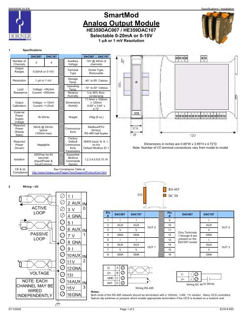
MAN0838-04-ENSmartModAnalog Output Module<strong>HE359DAC007</strong> / <strong>HE359DAC107</strong>Selectable 0-20mA or 0-10V1 µA or 1 mV ResolutionSpecifications / Installation1 SpecificationsNumber ofChannelsDAC007 DAC107 DAC007 DAC1072 4OutputRanges 0-20mA or 0-10VAuxiliaryVoltageTerminalType12V @ 20mA (4channels)Screw Type,RemovableResolutionLoadResistanceOutputCalibrationExternalPowerSupplyVoltageRequiredPower(SteadyState)RequiredPower(Inrush)IsolationCE & ULCompliance1 µA or 1 mVVoltage: >5KohmCurrent:
MAN0838-04-ENSpecifications / Installation3 Init Default SetupCommunication parameters will be set to INIT default after performing theprocedure:1. Install jumper between INIT and GND terminals of the RS-485 port.2. Apply power to Smartmod unit.3. Read parameter words to see current parameters.4. Write changes if necessary.D-D+GNDINITThe INIT Default RS485 Settings Are:Modbus ID = 1Baud rate = 9600Parity = NoneStop Bits = 1Data Bits = 8No handshake4 Configuration DATAABCDNote: There are 2 types of default settings possible:1. Factory default as described in section 1 (Specifications)2. Default after INIT as described in section 3 (INIT Default Setup)SmartMod Configuration settings are mapped into Modbus Register space. Thisconfiguration data may be modified with any Modbus/RTU Master device. Forconvenience, <strong>Horner</strong> <strong>APG</strong> has developed a variety of Cscape application fileswhich allow an OCS (Xle, NX, LX, QX) to act as a SmartMod configurator. Initialconfiguration of SmartMod module should be done on an individual basis, sinceall modules come from the factory with a default Modbus ID of 1. Once eachmodule on the network has its own unique Modbus ID, further configurationadjustments can be made with the entire network powered.All configuration parameters listed below (except 40012 Channel Enable) arestored in EPROM. That means they should not be constantly rewritten.Configuration Parameters – Registers 40001 through 40013ModbusDescription Min MaxRegisterDefault40001-40005Reserved40006Communications38.4kbaud, N, 8,See TableParameters1, RTU Mode40007 Modbus ID 1 255 140008Rx/Tx Delay (in 2mSsteps)0 255 0mS40009Watchdog Timer (in0.5s steps)0 255 10 (5s)40010 Modbus Coil Data Not Configuration Data – See I/O Data40011 Reserved40012 Reserved40013 Reserved40014 Output Type See Table0 (All ChannelsCurrent)Register 40006 (Communications Parameters) Bit DefinitionBits 7-15 Bit 6 Bit 5 Bit 4 Bit 3 Bit 2 Bit 1 Bit 0Unused Mode Parity Data Bits Baud RateValue Meaning Value Meaning0 = ASCII0 = 7 Data0 Mark 0 1200 baudModeBits1 Even1 2400 baud1 = RTUMode2 Odd 2 4800 baud1 = 8 Data3 Space 3 9600 baudBits4 19200 baud5-7 38400 baudRegister 40014 (Output Type) Bit DefinitionBit 4-15 Bit 3 Bit 2 Bit 1 Bit 0Output 3 Output 2 Output 1 Output 0Unused0 = Current (0-20mA)1 = Voltage (0-10V)5 Input/Output DATASmartMod Analog I/O utilizes both Modbus Registers (40001-40030) and Coils (1-11). It ispossible to access all data using Registers only, because the Coils can be accessed throughRegister 40010.The following tables lists all Modbus I/O data available.I/O Register Data (Registers 40010-40026)ModbusRegister Description Access Minimum Maximum Units40010Mirror ofCoil DataRead/Write n/a n/a n/a40015 Output 0 Read/Write 0 20000 1uA or 1mV40016 Output 1 Read/Write 0 20000 1uA or 1mV40017 Output 2 Read/Write 0 20000 1uA or 1mV40018 Output 3 Read/Write 0 20000 1uA or 1mV40019-40022Reserved40023Default/SafeValue Out 0Read/Write 0 20000 1uA or 1mV40024Default/SafeValue Out 1Read/Write 0 20000 1uA or 1mV40025Default/SafeValue Out 2Read/Write 0 20000 1uA or 1mV40026Default/SafeValue Out 3Read/Write 0 20000 1uA or 1mVModbusCoilDescriptionAccess00009WatchdogEnabledRead/Write00010 Watchdog Event Read/Write00011 Power-up Event Read/WriteModbusRegisterDescriptionAccess40010 bit 0WatchdogEnabledRead/Write40010 bit 1 Watchdog Event Read/Write40010 bit 2 Power-up Event Read/Write6 Installation / safetyWatchdog Event &Power-up EventOperationIf Coil 9 (WatchdogEnabled) is set, Coil 10(Watchdog Event) will setif the Watchdog Timeoutvalue is exceeded. TheWatchdog Timeout valueis set in Register 40009.When set, Coil 10 can bereset by the controllerwhen normalcommunicationsresumes.The Power-up Event(Coil 11) is set every timethe power is applied. Itcan be cleared by thecontroller if desired.Warning: Remove power from the OCS controller, CAN port, and any peripheralequipment connected to this local system before adding or replacing this or any module.a. All applicable codes and standards should be followed in the installation of this product.b. Shielded, twisted-pair wiring should be used for best performance.c. Shields may be terminated at the module terminal strip.d. In severe applications, shields should be tied directly to the ground block within the panel.e. Use the following wire type or equivalent: Belden 8441.For detailed installation and a handy checklist that covers panel box layout requirements andminimum clearances, refer to the hardware manual of the controller you are using.When found on the product, the following symbols specify:Warning: ElectricalShock Hazard.7 Technical SupportTechnical Support at the following locations:North America:Tel: 317 916-4274Fax: 317 639-4279Web: http://www.heapg.comEmail: techsppt@heapg.comWarning: Consultuser documentation.Europe:Tel: +353-21-4321266Fax: +353-21-4321826Web: http://www.horner-apg.comEmail: tech.support@horner-apg.comNo part of this publication may be reproduced without the prior agreement and writtenpermission of <strong>Horner</strong> <strong>APG</strong>, Inc. Information in this document is subject to change withoutnotice.__________________________________________________________________________________________________________________________________________________________________5/11/2009 Page 2 of 2 ECN # 950


