Datasheet - Augier
Datasheet - Augier
Datasheet - Augier

Create successful ePaper yourself
Turn your PDF publications into a flip-book with our unique Google optimized e-Paper software.
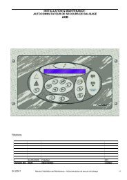
5.3 CCR to selector connections:Refer to the “installation manual” of the CCR.6 OPERATIONThe main switch Sn (n = number of ways + 1) allows the selection of the mode: Localcontrol or Remote control.The switches “ON/OFF” (S1, S2, ... S6) allow an individual local control of each way.The signal light “Circuits 1,2,...6” (H1, H2, ... H6) displays each selected circuit underlive voltage.The signal light “CCR ON” (Hn) displays the state of the CCR under live voltage.6.1 Local ModeSwitch Sn on “Local”Each selector way takes the status of its manual control:“ON” position: circuit under live voltage (corresponding runway lighting lit)“OFF” position : circuit switched off (corresponding runway light switch off)The corresponding signal lights to each way gives its state: lit if circuits are on ‘ON’,switched off if circuits are on “OFF”.Control and monitoring indication: Dry contacts or value in Jbus table(see#CONTROL AND MONITORING)Interlocking: All “push” actions on the front switch cause the opening of the drycontacts S1-S2. This contact, inserted into the CCR interlocking loop, forces it to stopduring the selecting or deselecting of the circuit. The switching is done when thecurrent is 0.Security of the door: The contact S1-S2 is also interrupted during the opening of thecubicle door, in the way that it stops the CCR, which supplies the now accessiblecircuits.60 21362 CIRCUIT SELECTOR Installation & Maintenance Page 7 / 32