Datasheet - Augier
Datasheet - Augier
Datasheet - Augier

You also want an ePaper? Increase the reach of your titles
YUMPU automatically turns print PDFs into web optimized ePapers that Google loves.
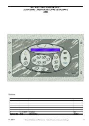
AUGIER SA.1 ère avenue – 2243 – BP13106513 CARROS CEDEX –FranceTél. +33 (0)4 92 08 62 00Fax. +33 (0)4 93 29 01 40C.e. home@augier.comSite. www.augier.comCIRCUIT SELECTORINSTALLATION & MAINTENANCE2-6 ways (alternate or simultaneous)Type IEC or FAA for power up to30kVACOMPLIANCE :OACI : Aerodrome Design Manual, Part 5, para. 3.2.1.3Type IEC : in accordance with IEC61820, 61821, 61822Type FAA : compliant with FAA AC 150/5345-5, L847Record of changes :3 22-12-2008 Ordering change ED RG2 16-10-2008 Interface number change ED RG1 13-10-2008 First issue ED RGRevision Date Description Author App.60 21362 CIRCUIT SELECTOR Installation & Maintenance Page 1 / 32
1 WARRANTY1.1 GuaranteeAUGIER’s goods are guaranteed for one year from delivery date on the signed deliverynote, and are guaranteed to be free from defects in materials used, design and manufacture.The guarantee covers repair, modification or replacement of parts or products recognisedto be defective, in the shortest possible time, at AUGIER’s cost, provided always that thegoods have been properly handled and stored prior installation, properly installed andproperly operated after installation.Unless otherwise specifically laid down in contract, the guarantee does not cover:• Costs of consignment to factory and re-consignment of defective goods to Buyer• If these are repaired in AUGIER’s factory;• Travelling & sojourn expenses of AUGIER’s personnel if goods have to be repairedon site; assembly and dismantling of any goods other than those recognised to bedefective; expenses incurred for waiting times by AUGIER’s personnel on site forreasons independent of their will;• Unjustified travel expenses.Guarantee shall not apply in the following cases:• Defects in materials supplied by Buyer or from any designs imposed by them;• Repairs or replacements due to normal wear and tear, or damages or accidents.• Repairs or replacements due to damages or accidents resulting from negligence or lackof due care, inadequate supervision or maintenance, or erroneous use of the equipmentor software;• Any other causes for which AUGIER shall not be held responsible, e.g. resultingfrom an case of Force Majeure.• When Buyer has replaced AUGIER’s parts with other parts.Buyer must inform AUGIER in writing and without delay of any defects in goods, givingall necessary information and detailed description of how equipment has been utilised,together with purchase date. Buyer undertakes not to have repairs carried out by thirdparties; any repairs carried out without AUGIER’s express prior agreement shall invalidatethe guarantee.It is expressly agreed between the two parties that Buyer cannot avail himself of thebeneficial dispositions contained in the guarantee without having first satisfied paymentconditions laid down in contract60 21362 CIRCUIT SELECTOR Installation & Maintenance Page 3 / 32
1.2 DisclaimersThis manual could contain technical or typographical errors. AUGIER reserves the right tomake changes and revise this manual from time to time without obligation to notify anyperson or organisation of such changes or revision.Values and measurements given in this manual are average values and are not binding.AUGIER disclaims any liability for damages suffered as a result of reliance on theinformation given in this manual, or the use of equipment or processes which this manualrefers.No guarantee is made that the use of the products, equipment, processes or information towhich this manual refers will not infringe any third party’s patent or rights. Informationgiven does not release the buyer from making their own tests.2 SAFETY2.1 Safety precautionsThis equipment is normally used or connected to circuits that may employ dangerous andlethal voltages. Extreme caution should be exercised by operating or maintenance peoplewhen working on or with this equipment.See IEC 61820 & 61821 standard (CCR and CS type IEC), or FAA AC150/5340-26advisory circular (CCR and CS type FAA), concerning safety rules and precautions. Whilepractical safety precautions have been incorporated in this equipment, the following rulesmust be strictly observed :• KEEP AWAY FROM LIVE CIRCUITS :Operating and maintenance people must at all time observe all safety regulations. Donot change components nor perform maintenance inside equipment with power ON orthe lighting loop energised.• RESUSCITATION :Operating and maintenance personnel should familiarise and keep themselves trainedwith resuscitation techniques found in widely published manuals about first aidinstructions.• ELECTROSTATIC DISCHARGE (ESD) :Electronic sub-assemblies and boards should be touched only for unavoidableoperation (replacement, for example). Before to operate, maintenance people mustfirst of all eliminate unwanted electronic charges, discharging his own body whiletouching a conductive earthed object or part. Electronic boards and components aspower semiconductors must be stored and carried an conductive packing.• DESTRUCTION :In case of dismantling, scrapping or placing out of service, the user must follow all therequired precautions for component, materials or equipment elimination, according thelocal rules.60 21362 CIRCUIT SELECTOR Installation & Maintenance Page 4 / 32
2.2 EEC directivesThis equipment complies with the requirements of EC directives :• 89/336/EEC, 92/31/EEC and 93/68/EEC with regard ofElectromagnetic Compatibility• 73/23/EEC with regard of Low Voltage Equipment3 OVERVIEW:Circuit Selector is intended to provide two alternate circuits selection. The power relays andinterlock to avoid commutations in charge are driven by the CS electronic.It provides “local” and “remote” control, according the choice of local switches present onthe front door of the cabinet. The described version is compliant with ICAO requests andIEC standards.The circuit selector can de ordered in compliance with FAA AC150/5345-5. For thatexecution, the selector provide double HV relays for each circuit, and can be reversed (letterR at the end of the P/N, see: #ORDERING INFORMATION) for manual switch-overoperations.The 2 way circuit selector SC2-A is presented in the form of an indoor type cubicle, madefrom painted metal sheet, external dimensions being H 700 x L 500 x W 300 mm.The connection terminals can be accessed by opening the door (which as 2 “double barred”catches) using the key delivered with each cubicle.On the cubicle door there is a switch (type “turn”), with 3 different positions, which allowsthe choice of the function mode or of the CS. It equally supports the status signal lights foreach circuit.4 CONFIGURATION:The circuit selector can be alternate or simultaneous and the circuit selector can support 2 to6 ways.It is possible to check and change the configuration using INTERMODBUS software tochange values in the Jbus table (see #INTERMODBUS SOFTWARE).SELECTOR TYPE CONFIGURATIONSelector type Jbus address Slave Id Bit 7 to Bit 15 Bit 6 Bit 0 to Bit 5Alternate 69 250 X 0 XSimultaneous 69 250 X 1 XNUMBER OF CIRCUITS CONFIGURATIONCircuits Jbus address Slave Id Value2 to 6 197 250 2 to 660 21362 CIRCUIT SELECTOR Installation & Maintenance Page 5 / 32
5 INSTALLATION:Cubicle: It can be fixed with the help of 4 fixing lugs delivered with each cubicle (fixingonto the vertical surface).Input and output of cables: This is done through the foldable plaque at the bottom part,afterwards the installation of the cable channels or the stuffing glands is done, in accordanceto the needs of the operations of the installation (diameter and cable length, watertightnessrequired).5.1 Connections:The supply and interlocking connections are carried out on the terminal-block BN.Main supply: terminals L1-L2.Remote control & monitoring: terminals B1, B2 if wire control, SubD 9 ifRS485/RS422 control, RJ45 if MODBUS TCP control.Local indication of CCR ON : If used, terminals X1, X2 have to be connected to theterminals 18, 19 of the AENA Terminal-bloc of the CCR.CCR interlock : terminals S1, S2 (dry contact), to be connected to terminals S1-S2 ofthe CCR (DIAMANT, CARAT, DIAM4000 type).Earthing connection of the cabinet must be done externally.RS232 link to set selector parameters.5.2 Lighting loops connections:Pass lighting cables of circuit 1 to 6 through the holes of the bottom part of thecabinet.Connecting each circuit should be made by crimping lugs (Diam 6 mm) on thecable’s core.The power connection for the CCR is done on an isolating plate, at the bottom of thecubicle between the HV1 and HV2 screw terminals (screwer M6).The power connections of the two load circuits are done on the same isolating platebetween the screw terminals of Circuit 1 ... Circuit 6 (screwer M6).The earthing connections (earthing of the cubicle and shields of the cables) must bedone on the copper main earth lead, at the bottom of the cubicle (for screw M6).Take care to let enough distance between the core and the screen.60 21362 CIRCUIT SELECTOR Installation & Maintenance Page 6 / 32
5.3 CCR to selector connections:Refer to the “installation manual” of the CCR.6 OPERATIONThe main switch Sn (n = number of ways + 1) allows the selection of the mode: Localcontrol or Remote control.The switches “ON/OFF” (S1, S2, ... S6) allow an individual local control of each way.The signal light “Circuits 1,2,...6” (H1, H2, ... H6) displays each selected circuit underlive voltage.The signal light “CCR ON” (Hn) displays the state of the CCR under live voltage.6.1 Local ModeSwitch Sn on “Local”Each selector way takes the status of its manual control:“ON” position: circuit under live voltage (corresponding runway lighting lit)“OFF” position : circuit switched off (corresponding runway light switch off)The corresponding signal lights to each way gives its state: lit if circuits are on ‘ON’,switched off if circuits are on “OFF”.Control and monitoring indication: Dry contacts or value in Jbus table(see#CONTROL AND MONITORING)Interlocking: All “push” actions on the front switch cause the opening of the drycontacts S1-S2. This contact, inserted into the CCR interlocking loop, forces it to stopduring the selecting or deselecting of the circuit. The switching is done when thecurrent is 0.Security of the door: The contact S1-S2 is also interrupted during the opening of thecubicle door, in the way that it stops the CCR, which supplies the now accessiblecircuits.60 21362 CIRCUIT SELECTOR Installation & Maintenance Page 7 / 32
6.2 Remote Control ModeSwitch Sn on position “Remote”.Selection of circuit by wire control, Jbus RS485/RS422 or MODBUS TCP.(see#CONTROL AND MONITORING) Interlocking: All selection or deselection by remote control cause the dry contact S1-S2 to open for an average time of 200ms. This contact, inserted into the CCRinterlocking loop, force it to stop during the selection or deselection of circuit.Switching is done when at current 0.6.3 Mains supply LossIn remote control position, the removal of 48Vcc supply (or other voltage) of C1 orCx, or the removal of the main supply, or the removal of the two voltages, causes theswitching on (Lamps “ON”) of the two circuits, but don’t stop the CCR (by interlockaction)In local position, the removal of the mains supply have the same effect.What means that whatever the mode (local or remote control), the removal of themains supply (whether the control voltage is present or not), causes the CCR to runwith all circuits energized.7 Alarm indicationA signal light labelled “ALARM” is present in front of the cubicle.This light lit for 2 seconds after power on and must be off after the 2 seconds.During normal use, the “ALARM” light must be off. It will light on in case of interface boarddefault.IMPORTANT NOTICE :This control inputs configuration, as other configuration elements, are set in factoryaccording the kind of remote control board and the type of control supply.60 21362 CIRCUIT SELECTOR Installation & Maintenance Page 8 / 32
8 CONTROL AND MONITORING8.1 Wire remote control with 20 to 60Vdc control supply8.1.1 Wire remote control with EXTERNAL 20 to 60Vdc control supplyWhen delivered, the CS is configured in factory as :- “External” power supply: see Wiring remote control voltage configuration.Inputs (20 to 60 Vdc only)Terminal T1 Function FAA label Pin Type(if fitted)C1 T1-1 C1 control* B1 Input voltage with respect to CC2 T1-2 C2 control* B2 Input voltage with respect to CC3 T1-3 C3 control* B3 Input voltage with respect to CC4 T1-4 C4 control* B4 Input voltage with respect to CC5 T1-5 C5 control* B5 Input voltage with respect to CC6 T1-6 C6 control* CC Input voltage with respect to CC T1-14 C CCI Common to Pin1 to Pin 6 inputs*The loop is energized when the voltage is supplied on input.i The remote control protection fuse is marked as PFU2 on the interface board (5x20mm250V/500mAT)60 21362 CIRCUIT SELECTOR Installation & Maintenance Page 9 / 32
8.1.2 Wire remote control with INTERNAL 20 to 60Vdc control supplyWhen delivered, the CS is configured in factory as :- “Internal” power supply: see: Wiring remote control voltage configurationInputs (contacts free of voltage only)Terminal T1 Function FAA label Pin Type(if fitted)C1 T1-1 C1 control* B1 Contact or short-circuit with CC2 T1-2 C2 control* B2 Contact or short-circuit with CC3 T1-3 C3 control* B3 Contact or short-circuit with CC4 T1-4 C4 control* B4 Contact or short-circuit with CC5 T1-5 C5 control* B5 Contact or short-circuit with CC6 T1-6 C6 control* CC Contact or short-circuit with CC T1-14 C CCI Common to Pin1 to Pin 6 inputs*The loop is energized when the contact is closed.i The remote control protection fuse is marked as PFU2 on the interface board (5x20mm250V/500mAT)8.2 Wire remote control with 120Vac control supply60 21362 CIRCUIT SELECTOR Installation & Maintenance Page 10 / 32
8.4 Wiring remote control voltage configurationThe CS can be remotely controlled either by an external voltage (20 to 60 VDC or120Vac), or by “free potential” contacts (internal power supply 30VDC from the CS, oradditional 120Vac source). This choice is made by the values at address 70 in the Jbus table.CONTROL INPUTS CONFIGURATIONInputs configuration Fig Jbus address B7 B6 B5 B4 B3 B2 B1 B0External voltage +20Vto +60V-- to 1 70 X 0 X X X X 0 0control the inputsContacts to control theinputs.2 70 X 0 X X X X 0 124V-- internal voltageExternal voltage 115V~to control the inputs3 70 X 0 X X X X 1 0Internal voltage 115V~to control the inputs4 70 X 0 X X X X 1 060 21362 CIRCUIT SELECTOR Installation & Maintenance Page 13 / 32
8.5 RS485/RS422 Serial Link configuration:8.5.1 ConnectionsEach serial link is equipped with two SubD 9-pin (1 female and 1 male sockets).The links are electrically insulated from all the other circuits:Sub D connectors:Pin RS422/RS485 Pin Typefunction1 T+ Output2 T- Output3 NC4 NC5 NC6 R+ Input7 R- Input8 NC9 NC60 21362 CIRCUIT SELECTOR Installation & Maintenance Page 14 / 32
8.5.2 Network polarity and terminationPolarising resistors.Set the two switches to “ON” to activate the two polarising resistors on lines R- and R+.(value = 2200 ohms)Generally, these switches are set to ON for the CCR on the end of the line. For all otherCCRs linked on the same bus, leave them set to OFF.Termination impedance.- Set the two switches to “ON” to insert a 120 ohm resistance in the Jbus line.- This impedance must compulsorily be inserted in the last CCR in the line, and only in thisone.N.B.: do not forget to connect similar impedance on the input line of the master device(robot or micro-computer), if this is placed at the end of the line and does not carry one.RS422/RS485 network polarity and terminationLink number Function Dipswitch1Termination impedanceS5-1S5-2Polarising resistorsS5-3S5-42Termination impedanceS5-5S5-6Polarising resistorsS5-7S5-860 21362 CIRCUIT SELECTOR Installation & Maintenance Page 15 / 32
8.5.3 Serial link parametersThe asynchronous serial links are defined as follows:Preferred parameters : 9600 baud, 8 data bits, 1 stop bits, no parity.JBUS protocol with Id=1 at delivery.It is possible to change the speed and the ID in the “Serial Link” menu:• Speed: 2400-4800-9600-19200 Baud• ID: 1 to 249These changes are active after a device reset (mains disconnection).The 2 serial links access to the same jbus table with the same priority (the last order is theone taken).i The JBUS table is defined in #Jbus tableIt is possible to check and change the slave id and speed using INTERMODBUS software tochange values in the Jbus table (see #INTERMODBUS SOFTWARE).SLAVE IDJbus address Slave Id Default value Possible value25 250 1 1 to 249SPEED SETTING (Bauds)Jbus address Slave Id Default value Possible value26 250 9600 2400, 4800, 9600, 1920060 21362 CIRCUIT SELECTOR Installation & Maintenance Page 16 / 32
8.6 Ethernet link configuration:The circuit selector can be equipped with one or two Ethernet interfaces. The used protocol isMODBUS TCP (port 502).Supplied functions are : function 3 (number of words
8.7 CS control & monitoring using serial link or Ethernet linkWhen the two remote control are used (serial link or Ethernet link and wires), the seriallink / Ethernet link has the smallest priority.The address 199 in the CCR jbus table is used only to select the circuit(s)(grey boxes = circuit selected):8.7.1 Alternate CS controlAlternate ControlValue at address 199 Selected circuit6 5 4 3 2 101234568.7.2 Simultaneous CS controlSimultaneous ControlValue at address 199 Selected circuit6 5 4 3 2 101234….….61626360 21362 CIRCUIT SELECTOR Installation & Maintenance Page 18 / 32
8.7.3 CS monitoring8.7.3.1 Loops statusLoops statusLoop energized Value at address 1986 5 4 3 2 101234….….6162638.7.3.2 Local/Remote statusLocal / Remote statusLocal/Remote switch Value at address 0Local position 0Remote position 1288.8 Echelon link:The lonworks interface use an FT10 module.60 21362 CIRCUIT SELECTOR Installation & Maintenance Page 19 / 32
9 INTERMODBUS SOFTWAREThe software “Intermodbus” is provided with the selector. Using this software connected tothe RS232 link, it is possible to read or modify a value in the Jbus table.9.1 RS232 cableTo communicate with the selector, it is necessary using a crossed RS232 cable.<strong>Augier</strong> reference cable: 30 081379.2 Intermodbus using9.2.1 Communication parametersPort: computer serial link port numberBaudRate: serial link speed: value ataddress 26 (see #Serial link parameters)Default value: 9600 Baud60 21362 CIRCUIT SELECTOR Installation & Maintenance Page 20 / 32
9.2.2 Read valueFor example, reading the value at address 0with supervisor id (250), the result is 128(selector in remote mode, see#Local/Remote status)9.2.3 Write valueFor example, modifying the salve id of theselector (see #Serial link parameters).Slave Id was 1 become 2 writing the value2 at address 25 with supervisor id (250),60 21362 CIRCUIT SELECTOR Installation & Maintenance Page 21 / 32
10 ORDERING INFORMATIONThe Circuit Selector is identified by a serialised ordering number which indicates its type andparticularity. If needed, add all useful precision and optionsExample : SCS-IEC-1-2A-10-60-230-A4-000 = Circuit selector compliant to IEC, 6.6A, 2alternate ways, 60Hz/230V for max. 10kVA CCRs, with lightning arrestors, remote control20 to 60V external :+ one Ethernet port.S C S - I E C - 1 - 2 A - 1 0 - 6 0 - 2 3 0 - B 4 - 1 0 0SCS:Circuit selector family in wall mounting steel cabinetIEC : Compliant with IEC regulation (no circuit isolator, -20°C +55°C, supply +/-10%, dielectric 2xUn + 2500V)FAA : Compliant with FAA AC 150/5345-5 L-8471 : 6.6A2 : 20AnX : n = Number of ways or circuits (n
11 Selector replacement parts:See diagram 40 02522 (Circuit selector SC2A 2,5 to 10KVA), 45 04283 (Circuit selectorSC6S 2,5 to 30KVA), 45 04284 (Circuit selector SC2A 2,5 to 30KVA).12 Dimensions and diagrams :See diagrams 40 02522 next pages for SC2A selector, IEC type13 Electrical diagramSee diagrams 45 04283 (Circuit selector SC6S 2,5 to 30KVA) and 45 04284 (Circuitselector SC2A 2,5 to 30KVA).14 Jbus table60 21362 CIRCUIT SELECTOR Installation & Maintenance Page 23 / 32
SELECTOR JBUS TABLEAdr. R/W Mode Memory Label Detail Bit clear Bit set DefaultValue0 R Ram WarningsCommentsBit0Bit1Bit2Bit3Bit4Bit5Bit6Bit7 Local Remote Selector modeBit8Bit9Bit10Bit11Bit12Bit131 R Ram WATCHDOG 0x5555 / 0xAAAA(period = 2 second)20 R Ram Interface boardfirmware version1 to 25525 R/W Sup Eeprom Serial link ID 1 1 to 24926 R/W Sup Eeprom Serial link speed 9600 In Baud: 2400, 4800, 9600, 1920069 R/W Sup Eeprom Parameters 1 Bit0Bit1Bit2Bit3Bit4Bit5Bit6 Alternate Simultaneous 1Bit7Bit8Bit960 21362 CIRCUIT SELECTOR Installation & Maintenance Page 24 / 32
Adr. R/W Mode Memory Label Detail Bit clear Bit set DefaultValue70 R/W Sup Eeprom Interface boardcontrol104 R/W Sup Eeprom Options124 R Ram Interface boardinputs statusBit0 ExternalUaux supplyInternalUaux supplyComments0 U control voltage type Ext/IntBit1 24V-- Uaux supply 120V~ Uaux supply 0 U control voltage 24V--/120V~Bit2 Simple Jbus link Double Jbus link 0 If Jbus optionBit3 No Lonworks link Lonworks link 0 OptionBit4Bit5 Simple TCP/IP link Double TCP/IP link 0 If TCP/IP optionBit6 Wire common - NOT POSSIBLE 0 Wire control polarizationBit0 - -Bit1 -Bit2 -Bit3Bit4Bit5Bit6Bit7 TCP/IP 0Bit8 RS485/RS422 0Bit0 Off On IN1Bit1 Off On IN2Bit2 Off On IN3Bit3 Off On IN4Bit4 Off On IN5Bit5 Off On IN6Bit6 Off On IN7Bit7 Off On IN8Bit8 Off On IN9Bit9 Off On IN10Bit10 Off On IN11Bit11 Off On IN12Bit12 Off On IN13Bit13 External Uaux Internal Uaux supply U control voltage type Ext/IntsupplyBit14 24V-- Uaux supply 120V~ Uaux supply U control voltage 24V--/120V~Bit15 Common - Common + Wire control polarization60 21362 CIRCUIT SELECTOR Installation & Maintenance Page 25 / 32
Adr. R/W Mode Memory Label Detail Bit clear Bit set DefaultValue125 R Ram Interface boardrelays status 1126 R Ram Interface boardrelays status 2CommentsBit0 Off On OUT_K17Bit1 Off On OUT_K18Bit2 Off On OUT_K19Bit3 Off On OUT_K20Bit4 Off On OUT_K21Bit5 Off On OUT_K22Bit6 Off On OUT_K23Bit7 Off On OUT_K24Bit8 Off OnBit9 Off OnBit10 Off OnBit11 Off OnBit12 Off OnBit13 Off OnBit14 Off OnBit15 Off OnBit0 Off On OUT_K1Bit1 Off On OUT_K2Bit2 Off On OUT_K3Bit3 Off On OUT_K4Bit4 Off On OUT_K5Bit5 Off On OUT_K6Bit6 Off On OUT_K7Bit7 Off On OUT_K8Bit8 Off On OUT_K9Bit9 Off On OUT_K10Bit10 Off On OUT_K11Bit11 Off On OUT_K12Bit12 Off On OUT_K13Bit13 Off On OUT_K14Bit14 Off On OUT_K15Bit15 Off On OUT_K1660 21362 CIRCUIT SELECTOR Installation & Maintenance Page 26 / 32
Adr. R/W Mode Memory Label Detail Bit clear Bit set DefaultValue129 R/W Eeprom IP Mask module 1(bytes 0&1)Comments255.255 65535 (0 to 65535)130 R/W Eeprom IP Mask module 1255.0 65280 (0 to 65535)(bytes 2&3)131 R/W Eeprom IP Adress module 1192.168 (49320) (0 to 65535)(bytes 0&1)132 R/W Eeprom IP Adress module 1100.160 (25760) (0 to 65535)(bytes 2&3)133 R/W Eeprom IP Mask module 2255.255 65535 (0 to 65535)(bytes 0&1)134 R/W Eeprom IP Mask module 2255.0 65280 (0 to 65535)(bytes 2&3)135 R/W Eeprom IP Adress module 2192.168 (49320) (0 to 65535)(bytes 0&1)136 R/W Eeprom IP Adress module 2100.161 (25761) (0 to 65535)(bytes 2&3)194 R/W Sup Ram Soft download 85 in decimal5 1 to 6197 R/W Sup Eeprom Circuit selector:Circuits qty198 R Ram Circuit selectorstates199 R/W Eeprom Circuit selector:Circuit in remotemodeLoop energized 0 to 630 0 to 6 in alternate mode, 0 to 63 insimultaneous modeR: Read, W :WriteMode “Sup”: Write access via ID 250Address used in running mode60 21362 CIRCUIT SELECTOR Installation & Maintenance Page 27 / 32
15 PresentationType FAA, 2 ways :Type IEC, 2 ways :60 21362 CIRCUIT SELECTOR Installation & Maintenance Page 28 / 32
60 21362 CIRCUIT SELECTOR Installation & Maintenance Page 29 / 32
60 21362 CIRCUIT SELECTOR Installation & Maintenance Page 30 / 32
60 21362 CIRCUIT SELECTOR Installation & Maintenance Page 31 / 32
60 21362 CIRCUIT SELECTOR Installation & Maintenance Page 32 / 32