Throttle Body (5S–FE) - CelicaTech
Throttle Body (5S–FE) - CelicaTech Throttle Body (5S–FE) - CelicaTech
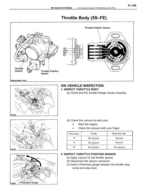
MFI AND SFI SYSTEMS–Air Induction System (Throttle Body (5S–FE))FI–199Throttle Body (5S–FE)ON–VEHICLE INSPECTION1. INSPECT THROTTLE BODY(a) Check that the throttle linkage moves smoothly.(b) Check the vacuum at each port.• Start the engine.• Check the vacuum with your finger.Port nameAt idleNo vacuumNo vacuumNo vacuumOther than idleVacuumVacuumNo vacuum2. INSPECT THROTTLE POSITION SENSOR(a) Apply vacuum to the throttle opener.(b) Disconnect the sensor connector.(c) Insert a thickness gauge between the throttle stopscrew and stop lever.
- Page 2 and 3: FI-200MFI AND SFI SYSTEMS-Air Induc
- Page 4 and 5: FI-202MFI AND SFI SYSTEMS - Air Ind
- Page 6 and 7: FI-204MFI AND SFI SYSTEMS-Air Induc
MFI AND SFI SYSTEMS–Air Induction System (<strong>Throttle</strong> <strong>Body</strong> (<strong>5S–FE</strong>))FI–199<strong>Throttle</strong> <strong>Body</strong> (<strong>5S–FE</strong>)ON–VEHICLE INSPECTION1. INSPECT THROTTLE BODY(a) Check that the throttle linkage moves smoothly.(b) Check the vacuum at each port.• Start the engine.• Check the vacuum with your finger.Port nameAt idleNo vacuumNo vacuumNo vacuumOther than idleVacuumVacuumNo vacuum2. INSPECT THROTTLE POSITION SENSOR(a) Apply vacuum to the throttle opener.(b) Disconnect the sensor connector.(c) Insert a thickness gauge between the throttle stopscrew and stop lever.
FI–200MFI AND SFI SYSTEMS–Air Induction System (<strong>Throttle</strong> <strong>Body</strong> (<strong>5S–FE</strong>))(d) Using an ohmmeter, measure the resistance be–tween each terminal.Clearance betweenlever and stop screw0 mm (0 in.)0.50 mm (0.020 in.)0.70 mm (0.028 in.)<strong>Throttle</strong> valve fullyopenBetweenterminalsVTA – E2I D L – E2I D L – E2VTA – E2VC – E2Resistance0.2 – 5.7 k2.3 k or lessInfinity2.0 – 10.2 k2.5 – 5.9 k(e) Reconnect the sensor connector.3. INSPECT AND ADJUST THROTTLE OPENERA. Warm up engineAllow the engine to warm up to normal operating tem–perature.B. Check idle speedIdle speed: 700 ± 50 rpm USA750 ± 50 rpm CANADAC. Check and adjust throttle opener setting speed(a) Disconnect the vacuum hose from the throttleopener, and plug the hose end.(b) Maintain the engine at 2,500 rpm.(c) Release the throttle valve.(d) Check that the throttle opener is set.<strong>Throttle</strong> opener setting speed:1,300–1,500 rpm (w/ Cooling fan OFF)
MFI AND SFI SYSTEMS–Air Induction System (<strong>Throttle</strong> <strong>Body</strong> (<strong>5S–FE</strong>))FI–201(e) Adjust the throttle opener setting speed by turningthe throttle opener adjusting screw.(f) Reconnect the vacuum hose to the throttle opener.REMOVAL OF THROTTLE BODY1. DISCONNECT CABLE FROM NEGATIVE TERMINALOF BATTERYCAUTION: Work must be started after approx. 20seconds or longer from the time the ignition switch isturned to the ”LOCK” position and the negative (–) ter–minal cable is disconnected from the battery.2. DRAIN ENGINE COOLANT (See page CO–6)3. (A/T)DISCONNECT THROTTLE CABLE FROM THROTTLELINKAGE4. DISCONNECT ACCELERATOR CABLE FROMTHROTTLE LINKAGE5. REMOVE AIR CLEANER CAP AND AIR CLEANER HOSE(a) Disconnect the air intake temperature sensor con–nector.(b) Disconnect the cruise control actuator cable fromthe clamp on the resonator.(c) Loosen the air cleaner hose clamp bolt.(d) Disconnect the four air cleaner cap clips.(e) Disconnect the air cleaner hose from the throttlebody, and remove the air cleaner cap together withthe resonator and air cleaner hose.6. DISCONNECT THROTTLE POSITION SENSORCONNECTOR7. DISCONNECT IAC VALVE CONNECTOR
FI–202MFI AND SFI SYSTEMS – Air Induction System (<strong>Throttle</strong> <strong>Body</strong> (<strong>5S–FE</strong>)) ~w8. DISCONNECT HOSES FROM THROTTLE BODY(a) PCV hose(b) Two vacuum hoses from EGR vacuum modulator(c) Vacuum hoses from EVAP VSV9. REMOVE THROTTLE BODY(a) Remove the four bolts, throttle body and gasket.(b) Disconnect the hoses from the throttle body, andremove the throttle body.(1) Water by–pass hose from water outlet(2) Water by–pass hose from water by–pass pipe(3) Air– hose from air tube10. IF NECESSARY, REMOVE IAC VALVE FROM THROTTLEBODYRemove the four screws, IAC valve and gasket.
MFI AND SFI SYSTEMS–Air Induction System (<strong>Throttle</strong> <strong>Body</strong> (<strong>5S–FE</strong>))FI–203INSPECTION OF THROTTLE BODY1. CLEAN THROTTLE BODY(a) Using a soft brush and carburetor cleaner, clean thecast parts.(b) Using compressed air, clean all the passages andapertures.NOTICE: To prevent deterioration, do not clean thethrottle position sensor.2. INSPECT THROTTLE VALVE(a) Apply vacuum to the throttle opener.(b) Check that there is no clearance between the throt–tle stop screw and throttle lever when the throttlevalve is fully closed.3. INSPECT THROTTLE POSITION SENSOR(See step 2 on page FI–199)4. IF NECESSARY, ADJUST THROTTLE POSITIONSENSOR(a) Loosen the two set screws of the sensor.(b) Apply vacuum to the throttle opener.(c) Insert a 0.60 mm (0.024 in.) thickness gauge, be–tween the throttle stop screw and stop lever.(d) Connect the test probe of an ohmmeter to the termi–nals IDL and E2 of the sensor.(e) Gradually turn the sensor clockwise until the ohm–meter deflects, and secure it with the two setscrews.(f) Recheck the continuity between terminals IDL andE2.Clearance betweenlever and stop screw0.50 mm (0.020 in.)0.70 mm (0.028 in.)Continuity (IDL – E2)ContinuityNo continuity
FI–204MFI AND SFI SYSTEMS–Air Induction System (<strong>Throttle</strong> <strong>Body</strong> (<strong>5S–FE</strong>))INSTALLATION OF THROTTLE BODY1. INSTALL IAC VALVE TO THROTTLE BODY(a) Place a new gasket on the throttle body.(b) Install the IAC valve with the four screws.2. INSTALL THROTTLE BODY(a) Connect the following hoses to the throttle body:(1) Water by–pass hose to water outlet(2) Water by–pass hose to water by–pass pipe(3) Air hose to air tube(b) Place a new gasket on the throttle body, facing theprotrusion downward.(c) Install the throttle body with the four bolts.Torque: 19 N–m (195 kgf–cm, 14 ft–lbf)HINT: Each bolt is indicated in the illustration.Bolt length: A 45 mm (1.77 in.)B 55 mm (2.17 in.)
MFI AND SFI SYSTEMS–Air Induction System (<strong>Throttle</strong> <strong>Body</strong> (<strong>5S–FE</strong>))FI–2053. CONNECT HOSES TO THROTTLE BODY(a) PCV hose(b) Two vacuum hoses to EGR vacuum modulator(c) Vacuum hose to EGR VSV4. CONNECT IAC VALVE CONNECTOR5. CONNECT THROTTLE POSITION SENSORCONNECTOR6. INSTALL AIR CLEANER CAP AND AIR CLEANER HOSE(a) Connect the air– cleaner hose to the throttle body.(b) Install the air cleaner cap together with the res–onator and air cleaner hose.(c) Connect the air intake temperature sensor con–nector.(d) Connect the cruise control actuator cable to theclamp on the resonator.7. CONNECT ACCELERATOR CABLE, AND ADJUST IT8. (A/T)CONNECT THROTTLE CABLE, AND ADJUST IT9. FILL WITH ENGINE COOLANT (See page CO–6)10. CONNECT CABLE TO NEGATIVE TERMINAL OFBATTERY


