

Maintenance-free Timer and Thermostatic Control ... - Grundfos
Maintenance-free Timer and Thermostatic Control ... - Grundfos
Maintenance-free Timer and Thermostatic Control ... - Grundfos

Create successful ePaper yourself
Turn your PDF publications into a flip-book with our unique Google optimized e-Paper software.
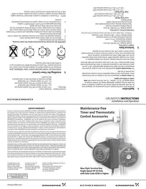
NOTE: If the pump is installed in a system, disconnect the power supply<strong>and</strong> either drain the system of liquid or close the isolation valves on eitherside of the circulator before removing the motor housing.CAUTION: Do not locate the terminal box below the motor housing.To change the terminal box position:1. Remove the (4) allen screws while supporting the motor.2. Carefully separate the motor from the pump chamber <strong>and</strong> rotate it to thedesired terminal box position.3. Replace the allen screws <strong>and</strong> tighten diagonally <strong>and</strong> evenly (7 ft-lb torque).4. Check that the motor shaft turns <strong>free</strong>ly. Remove the large screw in themiddle of the name plate, insert a small flat blade screwdriver into theslot at the end of the shaft, <strong>and</strong> turn gently.(Note:Not applicable to UP15-42F & UPS15-58FC models.)5. If the shaft does not turn <strong>free</strong>ly, repeat the disassembly/reassemblyprocess.X1. Application<strong>Grundfos</strong> timer <strong>and</strong> thermostatic control accessories are designed onlyfor use with specified <strong>Grundfos</strong> Series UP circulators installed in indoorhot water service systems. Applicable Series UP models include allsingle speed UP 10-15, 1-phase, 115 volt, 60 hertz pumps with datecodes of 0528 <strong>and</strong> higher.THERMOSTATIC CONTROLSupply Voltage:115-120 VAC, 60 hertzContact Rating (resistive):5.8 ampsType:Surface sensing, snap acting bimetallic discEnclosure:Environmentally sealedSwitch Modes:Low Temp Model105 ± 5°F (40 ± 2°C) pump switches OFF85 ± 6°F (29 ± 3°C) pump switches ONHigh Temp Model115 ± 5°F (46 ± 2°C) pump switches OFF105 ± 5°F (40 ± 2°C) pump switches ON2. Technical DataTIMER CONTROLSupply Voltage:115-120 VAC, 60 hertzContact Rating:16 ampsAmbient Temperature:-4°F to 175°FShortest Switching Interval:15 minute incrementSwitch Modes:“<strong>Timer</strong>”, “ON” Override, “OFF” OverrideProtection: Clear plastic cover for dust <strong>and</strong> moisture protection of the clock faceWhen the timer <strong>and</strong> thermostatic controls are installed together, inseries, the circulator operates ONLY at the preset clock times specifiedby the user AND ONLY when the temperature conditions of thethermostat are met. That is, if either the timer control or the thermostaticcontrol switch is open (off), the circulator will not operate.The timer control is designed to turn the circulator on <strong>and</strong> off at presettimes, allowing the user to select operation of the circulator during highuse periods of the day.The thermostatic control automatically turns the circulator off when thetemperature in the hot water line exceeds approximately 130°F (as thecase of periods with no dem<strong>and</strong>) <strong>and</strong> back on when the temperature fallsbelow approximately 110°F (as in the case of periods with high dem<strong>and</strong>).Contact Position: Normally closedMounting: (1/2”) Clip-on type for 5/8” O.D. system piping size(i.e., 1/2” I.D. copper tubing or 3/8” steel pipe)(3/4”) Clip-on type for 7/8” O.D. system piping size(i.e., 3/4” I.D. copper tubing or 1/2” steel pipe)May be mounted on either the inlet or outlet piping ofthe circulator.3. Installing the <strong>Timer</strong> <strong>Control</strong>POSITION OF PUMP MOTOR SHAFT AND TERMINAL BOXAll Series UP circulators MUST be installed with the motor shaft in thehorizontal position. The pump terminal box MUST be located on top orto either side of the motor housing.GRUNDFOS INSTRUCTIONSInstallation <strong>and</strong> OperationLIMITED WARRANTYProducts manufactured by GRUNDFOS PUMPS CORPORATION (GRUNDFOS) are warranted tothe original user only to be <strong>free</strong> of defects in material <strong>and</strong> workmanship for a period of 24months from date of installation, but not more than 30 months from date of manufacture.GRUNDFOS' liability under this warranty shall be limited to repairing or replacing at GRUNDFOS'option, without charge, F.O.B. GRUNDFOS' factory or authorized service station, any product ofGRUNDFOS manufacture. GRUNDFOS will not be liable for any costs of removal, installation,transportation, or any other charges which may arise in connection with a warranty claim.Products which are sold but not manufactured by GRUNDFOS are subject to the warrantyprovided by the manufacturer of said products <strong>and</strong> not by GRUNDFOS' warranty. GRUNDFOSwill not be liable for damage or wear to products caused by abnormal operating conditions,accident, abuse, misuse, unauthorized alteration or repair, or if the product was not installed inaccordance with GRUNDFOS' printed installation <strong>and</strong> operation instructions.To obtain service under this warranty, the defective product must be returned to the distributoror dealer of GRUNDFOS products from which it was purchased together with proof of purchase<strong>and</strong> installation date, failure date, <strong>and</strong> supporting installation data. Unless otherwise provided,the distributor or dealer will contact the GRUNDFOS factory or authorized service station forinstructions. Any defective product to be returned to the factory or service station must be sentfreight prepaid; documentation supporting the warranty claim <strong>and</strong>/or a Return Authorizationmust be included if so instructed.GRUNDFOS WILL NOT BE LIABLE FOR ANY INCIDENTAL OR CONSEQUENTIAL DAMAGES, LOSSES, OREXPENSES ARISING FROM INSTALLATION, USE, OR ANY OTHER CAUSES. THERE ARE NO EXPRESS ORIMPLIED WARRANTIES, INCLUDING MERCHANTABILITY OR FITNESS FOR A PARTICULAR PURPOSE,WHICH EXTEND BEYOND THOSE WARRANTIES DESCRIBED OR REFERRED TO ABOVE.Some jurisdictions do not allow the exclusion or limitation of incidental or consequential damages<strong>and</strong> some jurisdictions do not allow limitations on how long implied warranties may last. Therefore,the above limitations or exclusions may not apply to you. This warranty gives you specificlegal rights <strong>and</strong> you may also have other rights which vary from jurisdiction to jurisdiction.<strong>Maintenance</strong>-<strong>free</strong><strong>Timer</strong> <strong>and</strong> <strong>Thermostatic</strong><strong>Control</strong> Accessories<strong>Grundfos</strong> Pumps Corp.17100 W.118th TerraceOlathe, Kansas 66061Telephone: (913) 227-3400Fax: (913) 227-3500L-UP-TL-092 Rev.10/05PRINTED IN USA<strong>Grundfos</strong> Canada, Inc.2941 Brighton Rd.Oakville, Ontario L6H 6C9Telephone: (905) 829-9533Fax: (905) 829-9512Bombas <strong>Grundfos</strong> de Mexico, S.A. de C.V.Boulevard TLC #15,Parque Industrial Stiva AeropuertoC.P. 66600 Apodaca, N.L. MexicoTelephone: 52-81-8144-4000Fax: 52-81-8144-4010New Style Terminal BoxSingle Speed UP-15 Onlywith Date Code 0528 or higher.www.grundfos.com
INSTALLATION PROCEDUREThe timer control accessory is electrically connected <strong>and</strong> mounted to thecirculator terminal box. Install as follows:1. Remove the retaining screws in the existing terminal box cover <strong>and</strong>remove the cover. The timer control unit replaces this cover.2. See “5. Electrical Hookup”, for specific wiring instructions for hookup asan individual component or in series with the thermostatic control.3. After wiring is completed <strong>and</strong> checked, install the timer control unit ontothe terminal box bracket <strong>and</strong> reinsert the terminal box screws. Be carefulnot to bind or leave exposed any terminal box wires.4. Installing the <strong>Thermostatic</strong> <strong>Control</strong>INSTALLATION PROCEDURE1. The thermostatic control is a surface temperature sensing device thatmust be in contact with the system piping to operate properly. Separatemodels include clip-on mounts for 3/4” (7/8” O.D.) <strong>and</strong> 1/2” (5/8” O.D.)copper tubing. These models are also suitablefor use with 12” <strong>and</strong> 3/8”schedule 40 steel pipe, respectively.AquastatTerminal Box7 81 2 3 4 5 6L NGreenCapacitorBlackWhiteBlackWhiteYellowBlueWhiteLYellow<strong>Timer</strong>2 1M3 4BlueBlue12345T/SPump2 1M<strong>Timer</strong>NWIRING DIAGRAMFOR TIMER ANDAQUASTAT2. See “5 Electrical Hook-up”, for specific wiring instructions for hook-up asan individual component or in series with the timer control.3. Use a common strain relief for the power <strong>and</strong> aquastat cords.5. Electrical Hook-upAll electrical work should be performed by a qualified electrician inaccordance with the latest edition of the National ElectricCode <strong>and</strong> localcodes <strong>and</strong> regulations.Verify the electrical supply to be certain the voltage, phase <strong>and</strong>frequency match that of the circulator <strong>and</strong> accessory components.WARNING: Terminal Block Connections 1-8; Factoryconnections only, NO field wiring required6. Setting <strong>and</strong> Operating the <strong>Timer</strong> <strong>Control</strong> <strong>and</strong>Starting the PumpPROGRAMMING RINGTIMING ARROWMANUAL SWITCHPROGRAMMING TABSWIRING DIAGRAM FORTIMER CONTROL ONLYTerminal Box7 81 2 3 4 5 6L NGreenCapacitorBlackWhiteWhiteYellowBlueL<strong>Timer</strong>2 1Pump3 4 2 1BlueBlueYellowM12345M<strong>Timer</strong>NNOTE: Before the circulator is started, the system must be filled with liquid <strong>and</strong> vented.1. Set the timer switch to the actual time by turning the programming ring inthe direction of the arrow until the timing arrow points to the actual timeon the ring.2. Switch on the power supply to the circulator <strong>and</strong> set the manual switch tothe “ON” position. The circulator will now start.3. Set the required “ON”/”OFF” times on the programming ring by pushingthe programming tabs either away from or toward the center of the ring.Tabs pushed away from the center indicate circulator switched ”ON” whiletabs pushed toward the center indicate circulator switched “OFF”.CapacitorWIRING DIAGRAMFOR AQUASTATCONTROL ONLY1 2 3 4 5 6LBlack7 8NWhiteTerminal BoxGreenLT/SWhiteBlackAquastatPump2 1MN4. Set the manual switch to the “TIMER” position. The circulator will nowstart/stop according to the settings of the programming tabs.5. For continuous operation, set the manual switch to the “ON” position. Toswitch the circulator off, set the manual switch to the “OFF” position. The“ON”/”OFF” modes may be used without affecting the function of eitherthe programming ring or the timer switch.6. In case of power outage the timer will not keep time. After powerhas been restored, the correct time of day must be reset by rotating theprogramming ring in the direction of the arrow until the timing arrowpoints to the actual time on the ring.


